Page 739 of 2572
A93972
Disconnect
HookPin
Turn
A93973
Plunger
Push
Turn
Seal Packing
A53051
NutNutA61989
A
B A
A
A
A
AB 14-14
- ENGINE MECHANICALVALVE CLEARANCE (2AZ-FE)
2507 Author�: Date�:
2005 HIGHLANDER REPAIR MANUAL (RM1144U)
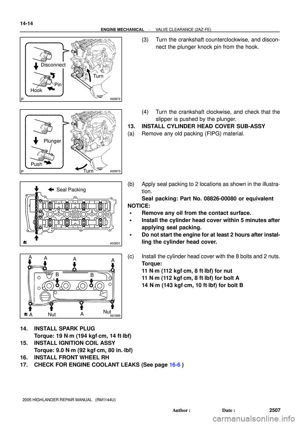
(3) Turn the crankshaft counterclockwise, and discon-
nect the plunger knock pin from the hook.
(4) Turn the crankshaft clockwise, and check that the
slipper is pushed by the plunger.
13. INSTALL CYLINDER HEAD COVER SUB-ASSY
(a) Remove any old packing (FIPG) material.
(b) Apply seal packing to 2 locations as shown in the illustra-
tion.
Seal packing: Part No. 08826-00080 or equivalent
NOTICE:
�Remove any oil from the contact surface.
�Install the cylinder head cover within 5 minutes after
applying seal packing.
�Do not start the engine for at least 2 hours after instal-
ling the cylinder head cover.
(c) Install the cylinder head cover with the 8 bolts and 2 nuts.
Torque:
11 NVm (112 kgfVcm, 8 ftVlbf) for nut
11 NVm (112 kgfVcm, 8 ftVlbf) for bolt A
14 NVm (143 kgfVcm, 10 ftVlbf) for bolt B
14. INSTALL SPARK PLUG
Torque: 19 NVm (194 kgfVcm, 14 ftVlbf)
15. INSTALL IGNITION COIL ASSY
Torque: 9.0 NVm (92 kgfVcm, 80 in.Vlbf)
16. INSTALL FRONT WHEEL RH
17. CHECK FOR ENGINE COOLANT LEAKS (See page 16-6)
Page 1139 of 2572
H01015G27651H43468H40065H44539
Telltale
Lamp
AssyAirbag
Sensor
Assy
Center CB
PAONP-AB
A17
DA
H10600H01012H01069H43467H43087
H44541
Telltale
Lamp
AssyAirbag
Sensor
Assy
Center
CGTC DLC3
DTC B1152/28
05-1356
- DIAGNOSTICSSUPPLEMENTAL RESTRAINT SYSTEM
1546 Author�: Date�:
2005 HIGHLANDER REPAIR MANUAL (RM1144U)
4 CHECK WIRE HARNESS (SHORT)
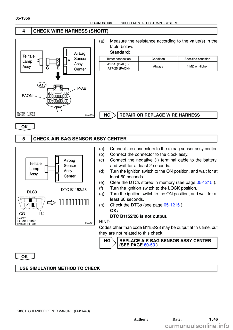
(a) Measure the resistance according to the value(s) in the
table below.
Standard:
Tester connectionConditionSpecified condition
A17-1 (P-AB) -
A17-25 (PAON)Always1 MW or Higher
NG REPAIR OR REPLACE WIRE HARNESS
OK
5 CHECK AIR BAG SENSOR ASSY CENTER
(a) Connect the connectors to the airbag sensor assy center.
(b) Connect the connector to the clock assy.
(c) Connect the negative (-) terminal cable to the battery,
and wait for at least 2 seconds.
(d) Turn the ignition switch to the ON position, and wait for at
least 60 seconds.
(e) Clear the DTCs stored in memory (see page 05-1215).
(f) Turn the ignition switch to the LOCK position.
(g) Turn the ignition switch to the ON position, and wait for at
least 60 seconds.
(h) Check the DTCs (see page 05-1215).
OK:
DTC B1152/28 is not output.
HINT:
Codes other than code B1152/28 may be output at this time, but
they are not related to this check.
NG REPLACE AIR BAG SENSOR ASSY CENTER
(SEE PAGE 60-53)
OK
USE SIMULATION METHOD TO CHECK
Page 1142 of 2572
H10600H01012H01069H43467H43087
H44541
Telltale
Lamp
AssyAirbag
Sensor
Assy
Center
CGTC DLC3
DTC B1152/28
- DIAGNOSTICSSUPPLEMENTAL RESTRAINT SYSTEM
05-1359
1549 Author�: Date�:
2005 HIGHLANDER REPAIR MANUAL (RM1144U)
10 CHECK AIR BAG SENSOR ASSY CENTER
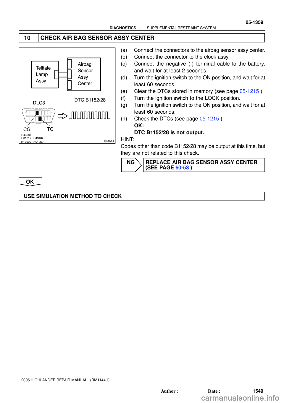
(a) Connect the connectors to the airbag sensor assy center.
(b) Connect the connector to the clock assy.
(c) Connect the negative (-) terminal cable to the battery,
and wait for at least 2 seconds.
(d) Turn the ignition switch to the ON position, and wait for at
least 60 seconds.
(e) Clear the DTCs stored in memory (see page 05-1215).
(f) Turn the ignition switch to the LOCK position.
(g) Turn the ignition switch to the ON position, and wait for at
least 60 seconds.
(h) Check the DTCs (see page 05-1215).
OK:
DTC B1152/28 is not output.
HINT:
Codes other than code B1152/28 may be output at this time, but
they are not related to this check.
NG REPLACE AIR BAG SENSOR ASSY CENTER
(SEE PAGE 60-53)
OK
USE SIMULATION METHOD TO CHECK
Page 1379 of 2572
05IS7-02
I38587*1
*2*1
*2*3
*4
05-1768
- DIAGNOSTICSNAVIGATION SYSTEM
1958 Author�: Date�:
2005 HIGHLANDER REPAIR MANUAL (RM1144U)
DIAGNOSIS DISPLAY DETAILED DESCRIPTION
HINT:
�This section contains a detailed description of displays within diagnostic mode.
�Illustrations may differ from the actual vehicle depending on the device settings and options. There-
fore, some detailed areas may not be shown exactly the same as on the actual vehicle.
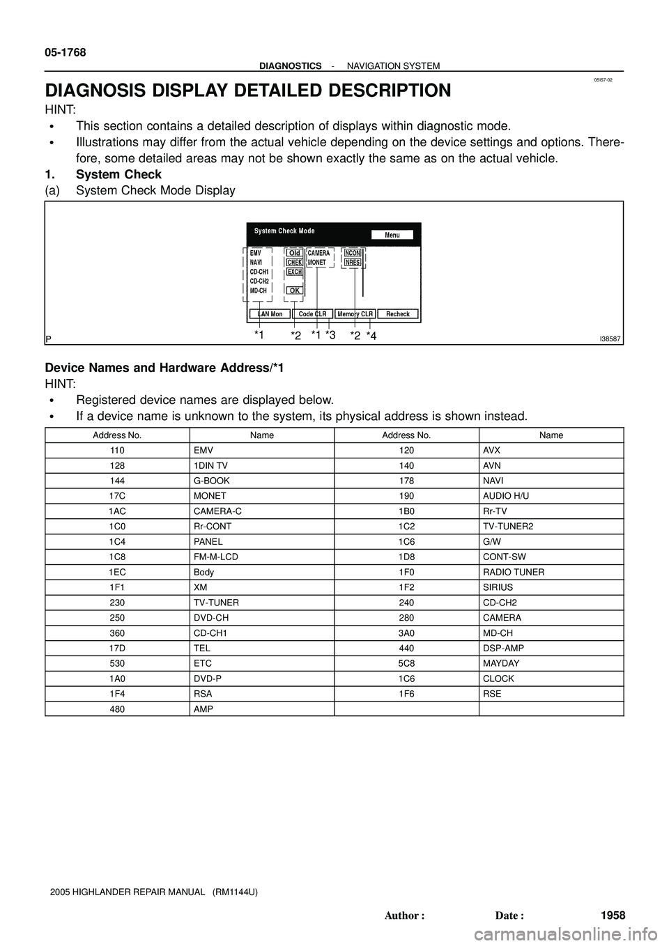
1. System Check
(a) System Check Mode Display
Device Names and Hardware Address/*1
HINT:
�Registered device names are displayed below.
�If a device name is unknown to the system, its physical address is shown instead.
Address No.NameAddress No.Name
11 0EMV120AV X
1281DIN TV140AV N
144G-BOOK178NAVI
17CMONET190AUDIO H/U
1ACCAMERA-C1B0Rr-TV
1C0Rr-CONT1C2TV-TUNER2
1C4PANEL1C6G/W
1C8FM-M-LCD1D8CONT-SW
1ECBody1F0RADIO TUNER
1F1XM1F2SIRIUS
230TV-TUNER240CD-CH2
250DVD-CH280CAMERA
360CD-CH13A0MD-CH
17DTEL440DSP-AMP
530ETC5C8MAYDAY
1A0DVD-P1C6CLOCK
1F4RSA1F6RSE
480AMP
Page 1467 of 2572
B51847
Driving Axis
ClockwiseCounterclock-
wise
4 5 6 7 8
B51844
05-1924
- DIAGNOSTICSPOWER WINDOW CONTROL SYSTEM
2114 Author�: Date�:
2005 HIGHLANDER REPAIR MANUAL (RM1144U)
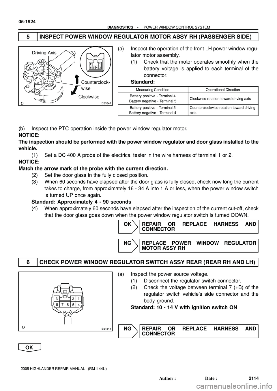
5 INSPECT POWER WINDOW REGULATOR MOTOR ASSY RH (PASSENGER SIDE)
(a) Inspect the operation of the front LH power window regu-
lator motor assembly.
(1) Check that the motor operates smoothly when the
battery voltage is applied to each terminal of the
connector.
Standard:
Measuring ConditionOperational Direction
Battery positive - Terminal 4
Battery negative - Terminal 5Clockwise rotation toward driving axis
Battery positive - Terminal 5
Battery negative - Terminal 4Counterclockwise rotation toward driving
axis
(b) Inspect the PTC operation inside the power window regulator motor.
NOTICE:
The inspection should be performed with the power window regulator and door glass installed to the
vehicle.
(1) Set a DC 400 A probe of the electrical tester in the wire harness of terminal 1 or 2.
NOTICE:
Match the arrow mark of the probe with the current direction.
(2) Set the door glass in the fully closed position.
(3) When 60 seconds have elapsed after the door glass is fully closed, check now long the current
takes to charge, from approximately 16 - 34 A into 1 A or less, when the power window switch
is turned UP once again.
Standard: Approximately 4 - 90 seconds
(4) When approximately 60 seconds have elapsed after the inspection of the current cut-off, check
that the door glass goes down when the power window regulator switch is turned DOWN.
OK REPAIR OR REPLACE HARNESS AND
CONNECTOR
NG REPLACE POWER WINDOW REGULATOR
MOTOR ASSY RH
6 CHECK POWER WINDOW REGULATOR SWITCH ASSY REAR (REAR RH AND LH)
(a) Inspect the power source voltage.
(1) Disconnect the regulator switch connector.
(2) Check the voltage between terminal 7 (+B) of the
regulator switch vehicle's side connector and the
body ground.
Standard: 10 - 14 V with ignition switch ON
NG REPAIR OR REPLACE HARNESS AND
CONNECTOR
OK
Page 1469 of 2572
B51848
Driving Axis
Clockwise
Counterclockwise
05-1926
- DIAGNOSTICSPOWER WINDOW CONTROL SYSTEM
2116 Author�: Date�:
2005 HIGHLANDER REPAIR MANUAL (RM1144U)
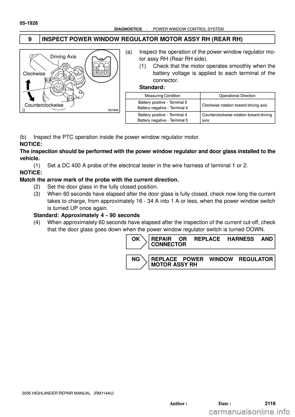
9 INSPECT POWER WINDOW REGULATOR MOTOR ASSY RH (REAR RH)
(a) Inspect the operation of the power window regulator mo-
tor assy RH (Rear RH side).
(1) Check that the motor operates smoothly when the
battery voltage is applied to each terminal of the
connector.
Standard:
Measuring ConditionOperational Direction
Battery positive - Terminal 5
Battery negative - Terminal 4Clockwise rotation toward driving axis
Battery positive - Terminal 4
Battery negative - Terminal 5Counterclockwise rotation toward driving
axis
(b) Inspect the PTC operation inside the power window regulator motor.
NOTICE:
The inspection should be performed with the power window regulator and door glass installed to the
vehicle.
(1) Set a DC 400 A probe of the electrical tester in the wire harness of terminal 1 or 2.
NOTICE:
Match the arrow mark of the probe with the current direction.
(2) Set the door glass in the fully closed position.
(3) When 60 seconds have elapsed after the door glass is fully closed, check now long the current
takes to charge, from approximately 16 - 34 A into 1 A or less, when the power window switch
is turned UP once again.
Standard: Approximately 4 - 90 seconds
(4) When approximately 60 seconds have elapsed after the inspection of the current cut-off, check
that the door glass goes down when the power window regulator switch is turned DOWN.
OK REPAIR OR REPLACE HARNESS AND
CONNECTOR
NG REPLACE POWER WINDOW REGULATOR
MOTOR ASSY RH
Page 1471 of 2572
B51849
Driving Axis
ClockwiseCounterclock-
wise
05-1928
- DIAGNOSTICSPOWER WINDOW CONTROL SYSTEM
2118 Author�: Date�:
2005 HIGHLANDER REPAIR MANUAL (RM1144U)
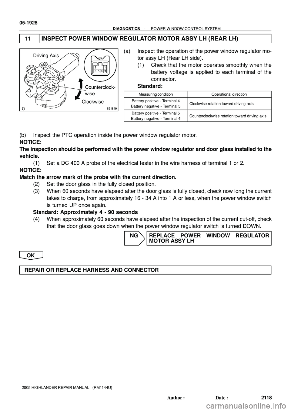
11 INSPECT POWER WINDOW REGULATOR MOTOR ASSY LH (REAR LH)
(a) Inspect the operation of the power window regulator mo-
tor assy LH (Rear LH side).
(1) Check that the motor operates smoothly when the
battery voltage is applied to each terminal of the
connector.
Standard:
Measuring conditionOperational direction
Battery positive - Terminal 4
Battery negative - Terminal 5Clockwise rotation toward driving axis
Battery positive - Terminal 5
Battery negative - Terminal 4Counterclockwise rotation toward driving axis
(b) Inspect the PTC operation inside the power window regulator motor.
NOTICE:
The inspection should be performed with the power window regulator and door glass installed to the
vehicle.
(1) Set a DC 400 A probe of the electrical tester in the wire harness of terminal 1 or 2.
NOTICE:
Match the arrow mark of the probe with the current direction.
(2) Set the door glass in the fully closed position.
(3) When 60 seconds have elapsed after the door glass is fully closed, check now long the current
takes to charge, from approximately 16 - 34 A into 1 A or less, when the power window switch
is turned UP once again.
Standard: Approximately 4 - 90 seconds
(4) When approximately 60 seconds have elapsed after the inspection of the current cut-off, check
that the door glass goes down when the power window regulator switch is turned DOWN.
NG REPLACE POWER WINDOW REGULATOR
MOTOR ASSY LH
OK
REPAIR OR REPLACE HARNESS AND CONNECTOR
Page 1494 of 2572
I40781
A/C Amplifier Assy
ACC A10 RADIO NO. 2
AM14GR13
Battery FL MAINInstrument Panel J/B Center J/B
3A V
2ACC 3 L
W2
63
1
1A 1C 1C1K
AM1
1
2
B
2 1
ALT
WF7
Fusible Link Block3I 13 11 I15
Ignition SW
- DIAGNOSTICSAIR CONDITIONING SYSTEM
05-1 175
1365 Author�: Date�:
2005 HIGHLANDER REPAIR MANUAL (RM1144U)
ACC POWER SOURCE CIRCUIT
CIRCUIT DESCRIPTION
This circuit supplies power to the A/C amplifier assy. It supplies power to the illumination for the clock.
WIRING DIAGRAM
05IU4-01