Page 1790 of 2572
A76973
ECM
Fuel Tank
Charcoal
Canister EVAP VSV
Vapor Pressure
Sensor
CCV EVAP Service
PortIntake Air
Throttle
Valve
Fuel Tank Cap
Air Cleaner Case
Charcoal Canister Filter Charcoal Filter
Intake Manifold
Purge Line
Air Inlet Line EVAP Line Purge Line
Diaphragm
(Atmospheric Pressure)
Restrictor
Passage
When VSV for EVAP is opened, partial vacuum is created
When CCV is
opened, air is
drawn or released
Leak Detection Area
Fig. 1
(purge valve) 05-574
- DIAGNOSTICSSFI SYSTEM (3MZ-FE)
764 Author�: Date�:
2005 HIGHLANDER REPAIR MANUAL (RM1144U)
Page 1994 of 2572

I37216
Television Display Assy:
TX+
TX-
Multi display Controller Sub-assy:
TX2+TX2-
R28
R30
- DIAGNOSTICSREAR SEAT ENTERTAINMENT SYSTEM
05-1747
1937 Author�: Date�:
2005 HIGHLANDER REPAIR MANUAL (RM1144U)
INSPECTION PROCEDURE
1 SERVICE CHECK MODE(TELEVISION DISPLAY ASSY)
(a) Perform service check.
(1) Start the diagnosis system and read check result for television display assy.
Standard:
AºNCONº is displayed or no display (Rr-TV)
BºOKº is displayed
B REPLACE MULTI-DISPLA Y CONTROLLER
SUB-ASSY (See page 67-23)
A
2 CHECK HARNESS AND CONNECTOR(TELEVISION DISPLAY ASSY -
MULTI-DISPLA Y CONTROLLER SUB-ASSY)
(a) Disconnect the connector from the television display assy
and multi-display controller sub-assy.
(b) Measure the resistance according to the values in the
table below.
Standard:
Tester connectionConditionSpecified condition
TX+ - TX2+AlwaysBelow 1 W
TX- - TX2-AlwaysBelow 1 W
TX+ - Body groundAlways10 kW or higher
TX- - Body groundAlways10 kW or higher
NG REPAIR OR REPLACE HARNESS OR
CONNECTOR
OK
REPLACE TELEVISION DISPLAY ASSY (See page 67-26)
Page 2045 of 2572
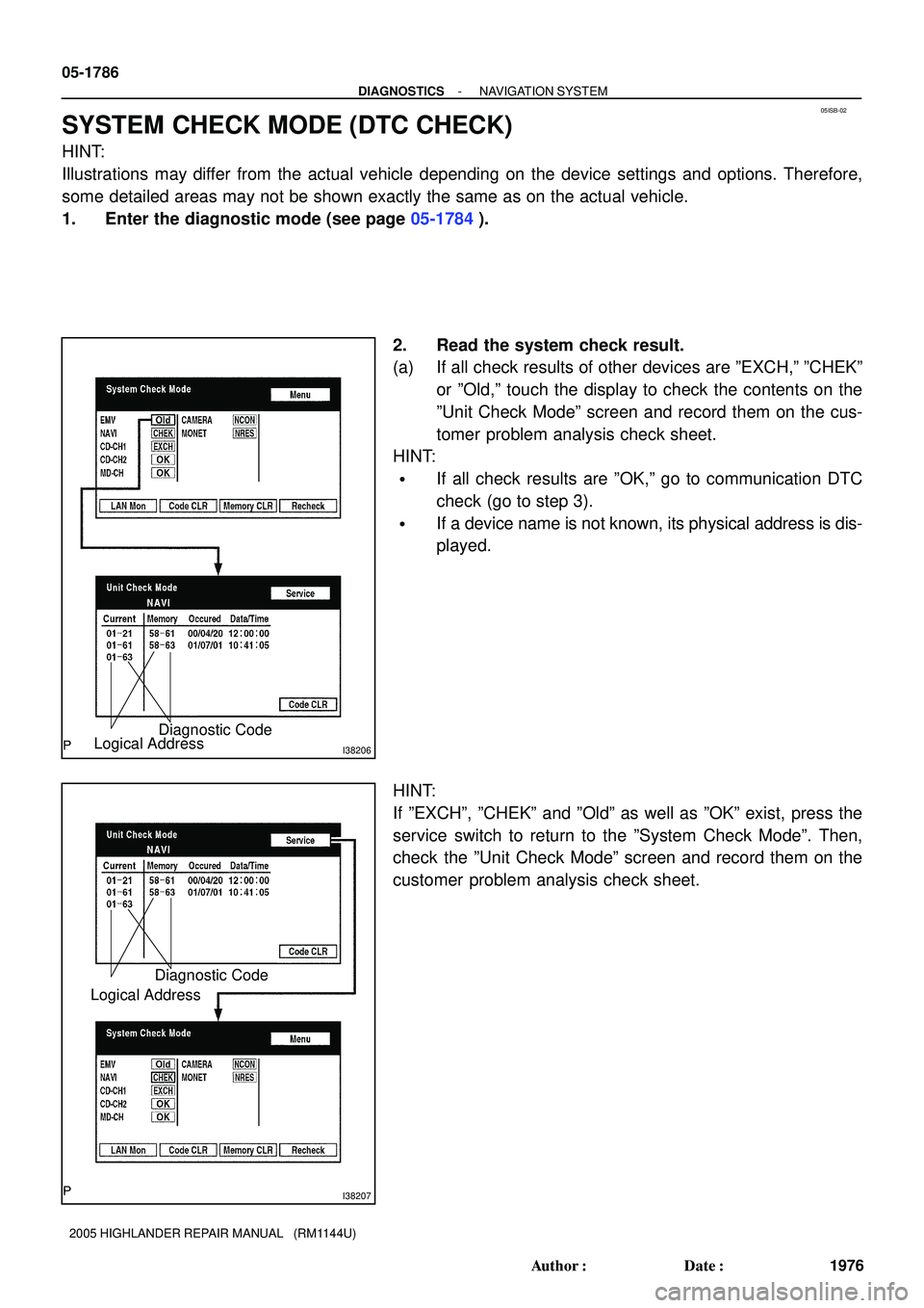
05ISB-02
I38206Logical AddressDiagnostic Code
I38207
Logical AddressDiagnostic Code
05-1786
- DIAGNOSTICSNAVIGATION SYSTEM
1976 Author�: Date�:
2005 HIGHLANDER REPAIR MANUAL (RM1144U)
SYSTEM CHECK MODE (DTC CHECK)
HINT:
Illustrations may differ from the actual vehicle depending on the device settings and options. Therefore,
some detailed areas may not be shown exactly the same as on the actual vehicle.
1. Enter the diagnostic mode (see page 05-1784).
2. Read the system check result.
(a) If all check results of other devices are ºEXCH,º ºCHEKº
or ºOld,º touch the display to check the contents on the
ºUnit Check Modeº screen and record them on the cus-
tomer problem analysis check sheet.
HINT:
�If all check results are ºOK,º go to communication DTC
check (go to step 3).
�If a device name is not known, its physical address is dis-
played.
HINT:
If ºEXCHº, ºCHEKº and ºOldº as well as ºOKº exist, press the
service switch to return to the ºSystem Check Modeº. Then,
check the ºUnit Check Modeº screen and record them on the
customer problem analysis check sheet.
Page 2047 of 2572
I38210
05-1788
- DIAGNOSTICSNAVIGATION SYSTEM
1978 Author�: Date�:
2005 HIGHLANDER REPAIR MANUAL (RM1144U)
HINT:
If check results of other devices are ºCHEK,º press the ºServiceº
switch to return to the original ºLAN Monitorº screen. Then,
check the individual communication diagnostic screen for the
next device and record the result on the customer problem anal-
ysis check sheet.
Page 2093 of 2572

05IRH-01
30 kHz 300 kHz 3 MHz 30 MHz 300 MHz
LF MF HF VHF
AM FM
Frequency modulation Frequency
Designation
Radio wave
Modulation Amplitude modulation
BE2818
FM (Stereo)
FM (Monaural)
AM
BE2819
PhasingIonosphere
- DIAGNOSTICSAUDIO SYSTEM
05-161 1
1801 Author�: Date�:
2005 HIGHLANDER REPAIR MANUAL (RM1144U)
AUDIO SYSTEM
DESCRIPTION
1. RADIO WAVE BAND
The radio wave bands used in radio broadcasting are as follows:
LF: Low Frequency
MF: Medium Frequency
HF: High Frequency
VHF: Very High Frequency
2. SERVICE AREA
(a) There is a great difference in the size of the service areas
for AM and FM broadcasting. Sometimes an FM stereo
broadcast cannot be received even though AM can be re-
ceived very clearly.
FM stereo has the smaller service area, it also picks up
static and other types of interference (ºnoiseº) easily.
3. RECEPTION PROBLEMS
HINT:
Besides the problem of static, there are other problems, such as ºphasingº, ºmultipathº and ºfade outº. These
problems are caused not by electrical noise but by the nature of the radio waves themselves.
(a) Phasing
Besides electrical interference, AM broadcasts are also
susceptible to other types of interference, especially at
night. This is because AM radio waves bounce off the ion-
osphere at night. These radio waves then interfere with
the signals that reach the vehicle's antenna directly from
the same transmitter. This type of interference is called
ºphasingº.
Page 2112 of 2572
The sections shown in the figure below are filled with foamed material to provide noise insulation.
After repairing these sections or their peripheries, refill with foamed materials
HINT:
1) Use the service holes located on the reverse side of the body panel to refill with foamed materials.
2) When handling foamed material, follow the directions of the material's manufacturer.
F16737
PAINT � COATINGPC-8
FOAMED MATERIAL APPLICATION AREAS
Page 2113 of 2572

'05 HIGHLANDER_U (L/O 0409)
i
2005 HIGHLANDER from Nov. '04 Prod. (OM48570U)
Foreword
Welcome to the growing group of value- conscious people who drive Toyotas. We are proud of the advanced engineering and
quality construction of each vehicle we build.
This Owner 's Manual explains the operation of your new Toyota. Please read it thoroughly and have all the occupants
follow the instructions carefully. Doing so will help you enjoy many years of safe and trouble- free motoring. For
important information about this manual and your Toyota, read the following pages carefully.
When it comes to service, remember that your Toyota dealer knows your vehicle very well and is interested in your complete
satisfaction. Your Toyota dealer will provide quality maintenance and any other assistance you may require.
If there is not a Toyota dealer near you, or you need emergency assistance for any reason, please call the following number:
�U.S. OWNERS:Toyota Customer Assistance Center Toll- free: 1- 800- 331- 4331
�CANADIAN OWNERS:Toyota Canada Customer Interaction CentreToll- free: 1- 888- TOYOTA- 8 (1- 888- 869- 6828)
Please leave this Owner 's Manual in this vehicle at the time of resale. The next owner will need this information also.
All information and specifications in this manual are current at the time of printing. However, because of Toyota's policy of
continual product improvement, we reserve the right to make changes at any time without notice.
Please note that this manual applies to all models and explains all equipment, including options. Therefore, you may
find some explanations for equipment not installed on your vehicle.
W2004 TOYOTA MOTOR CORPORATION
All rights reserved. This material may not be reproduced or copied, in whole or in part, without the written permission of Toyota
Motor Corporation.
Page 2114 of 2572

NOTICE
When handling supplemental restraint system components (removal,
installation or inspection, etc.), always follow the direction given in the repair
manuals listed above to prevent accidents and supplemental restraint
system malfunction.
�2004
All rights reserved. This book may not be
reproduced or copied, in whole or in part, without
the written permission of Toyota Motor
Corporation.
First Printing : Jul. 21, 2004 01-040721-00
FOREWORD
This wiring diagram manual has been prepared to provide
information on the electrical system of the 2005
HIGHLANDER.
Applicable models: MCU23, 28 Series
ACU20, 25 Series
For service specifications and repair procedures of the above
models other than those listed in this manual, refer to the
following manuals;
Manual Name
Pub. No.
�2005 HIGHLANDER Repair Manual
�2005 TOYOTA New Car FeaturesRM1144U
NCF275U
All information in this manual is based on the latest product
information at the time of publication. However, specifications
and procedures are subject to change without notice.


