Page 1441 of 2572
A85255
Pressure Gauge
Pressure
B06546
- DIAGNOSTICSSFI SYSTEM (2AZ-FE)
05-343
533 Author�: Date�:
2005 HIGHLANDER REPAIR MANUAL (RM1144U)
28 REPLACE FUEL TANK CAP ASSY
HINT:
When installing the fuel tank cap, tighten it until a few click sounds are heard.
NEXT Go to step 37
29 REPAIR EVAP LEAK PART
(a) Reinstall the fuel cap.
(b) Remove the exhaust tail pipe.
(c) Remove the heat insulator under the canister.
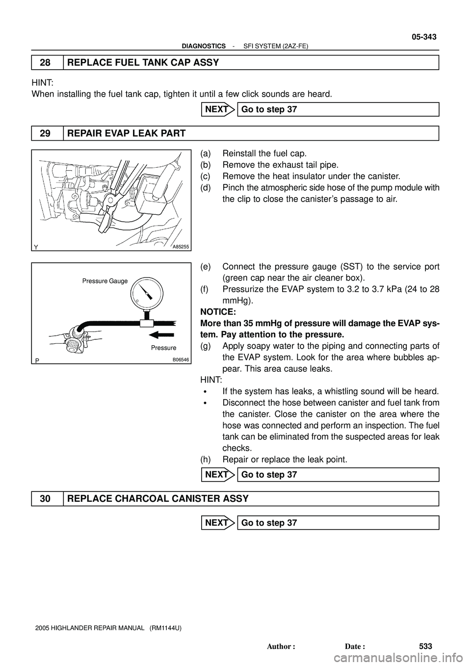
(d) Pinch the atmospheric side hose of the pump module with
the clip to close the canister's passage to air.
(e) Connect the pressure gauge (SST) to the service port
(green cap near the air cleaner box).
(f) Pressurize the EVAP system to 3.2 to 3.7 kPa (24 to 28
mmHg).
NOTICE:
More than 35 mmHg of pressure will damage the EVAP sys-
tem. Pay attention to the pressure.
(g) Apply soapy water to the piping and connecting parts of
the EVAP system. Look for the area where bubbles ap-
pear. This area cause leaks.
HINT:
�If the system has leaks, a whistling sound will be heard.
�Disconnect the hose between canister and fuel tank from
the canister. Close the canister on the area where the
hose was connected and perform an inspection. The fuel
tank can be eliminated from the suspected areas for leak
checks.
(h) Repair or replace the leak point.
NEXT Go to step 37
30 REPLACE CHARCOAL CANISTER ASSY
NEXT Go to step 37
Page 1483 of 2572
I36159E51630I38853
A2
Magnet Clutch Assy Connector
Wire Harness View:ECM Connector
Wire Harness View:
E6
ACMG
- DIAGNOSTICSAIR CONDITIONING SYSTEM
05-1 193
1383 Author�: Date�:
2005 HIGHLANDER REPAIR MANUAL (RM1144U)
6 CHECK HARNESS AND CONNECTOR
(a) Disconnect the connector.
(b) Measure the voltage according to the value(s) in the table
below.
Standard:
Tester connectionConditionSpecified condition
A2-3 - Body ground
Ignition switch ON
When using service wire,
terminal E6-2 (ACMG)
and Body ground are not
connect
Below 1 V
A2-3 - Body ground
Ignition switch ON
When using service wire,
terminal E6-2 (ACMG)
and Body ground are con-
nect
10 to 14 V
NG REPAIR OR REPLACE HARNESS AND
CONNECTOR
OK
REPLACE ECM
Page 1512 of 2572
05BYH-15
F45104
F45105
Bypass Wire
F45106
05-2090
- DIAGNOSTICSCAN COMMUNICATION SYSTEM
2280 Author�: Date�:
2005 HIGHLANDER REPAIR MANUAL (RM1144U)
CAN COMMUNICATION SYSTEM
PRECAUTION
1. HANDLING PRECAUTIONS ON STEERING SYSTEM
(a) Care must be taken when replacing parts. Incorrect replacement could affect the performance of the
steering system and result in a driving hazard.
2. HANDLING PRECAUTIONS ON SRS AIRBAG SYSTEM
(a) The HIGHLANDER is equipped with a SRS (Supplemental Restraint System), such as the driver air-
bag and front passenger airbag. Failure to carry out service operation in the correct sequence could
cause the SRS to unexpectedly deploy during servicing, possibly leading to a serious accident. Before
servicing (including removal or installation of parts, inspection or replacement), be sure to read the pre-
cautionary notice for the Supplemental Restraint System (see page 60-1).
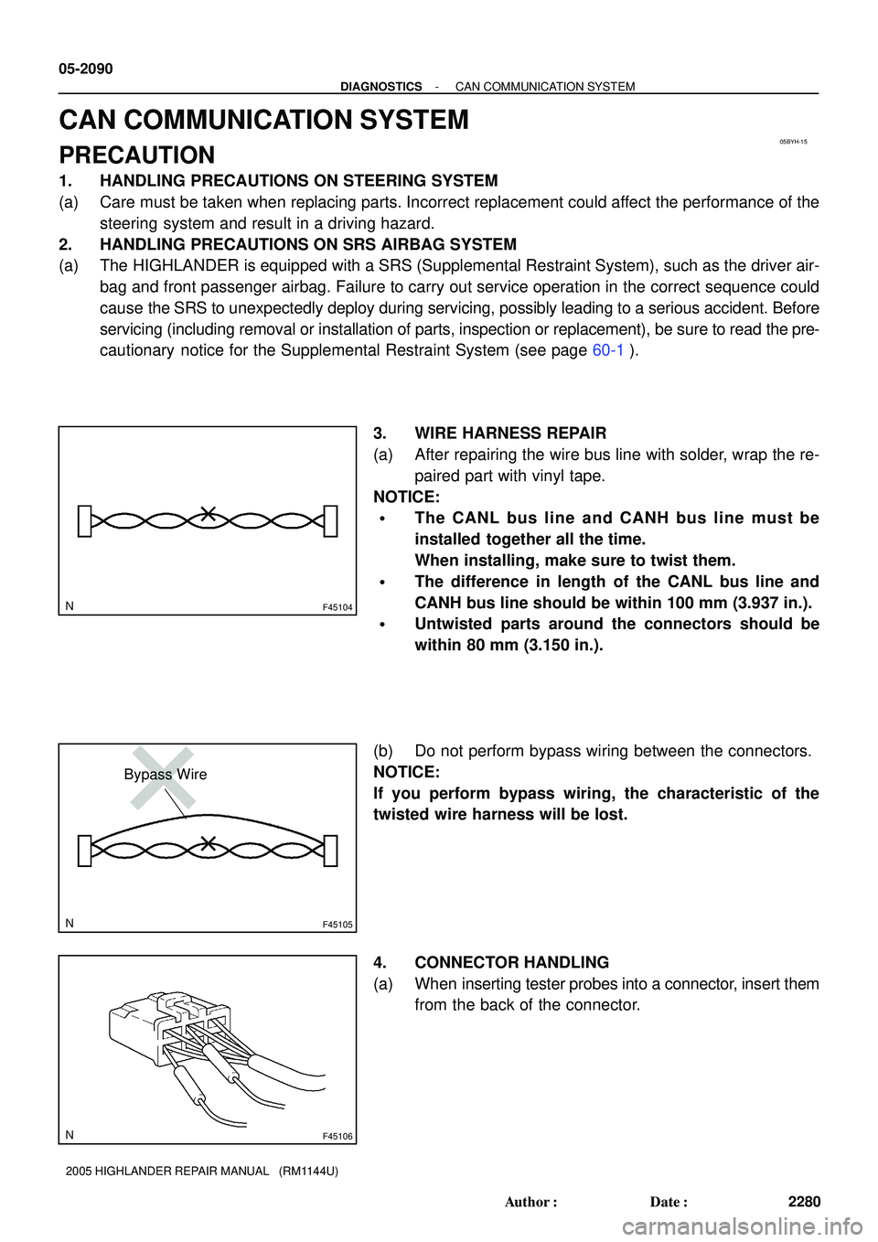
3. WIRE HARNESS REPAIR
(a) After repairing the wire bus line with solder, wrap the re-
paired part with vinyl tape.
NOTICE:
�The CANL bus line and CANH bus line must be
installed together all the time.
When installing, make sure to twist them.
�The difference in length of the CANL bus line and
CANH bus line should be within 100 mm (3.937 in.).
�Untwisted parts around the connectors should be
within 80 mm (3.150 in.).
(b) Do not perform bypass wiring between the connectors.
NOTICE:
If you perform bypass wiring, the characteristic of the
twisted wire harness will be lost.
4. CONNECTOR HANDLING
(a) When inserting tester probes into a connector, insert them
from the back of the connector.
Page 1532 of 2572
E74263
B11
B11-3 Multiplex Network Body ECU
Connector Front View:
- DIAGNOSTICSLIGHTING SYSTEM
05-1557
1747 Author�: Date�:
2005 HIGHLANDER REPAIR MANUAL (RM1144U)
INSPECTION PROCEDURE
1 PERFORM ACTIVE TEST USING HAND-HELD TESTER
(a) Connect the hand-held tester to the DLC3.
(b) Turn the ignition switch to the ON position and turn the hand-held tester main switch on.
(c) Select the item below in the ACTIVE TEST and then check the relay operation.
BODY NO.1 (MULTIPLEX NETWORK BODY ECU):
ItemTest DetailsDiagnostic Note
HEAD LIGHTHeadlamp relay ON/OFF-
OK: Headlamp comes on.
NG Go to step 2
OK
PROCEED TO NEXT CIRCUIT INSPECTION SHOWN IN PROBLEM SYMPTOMS TABLE
(SEE PAGE 05-1538)
2 INSPECT MULTIPLEX NETWORK BODY ECU
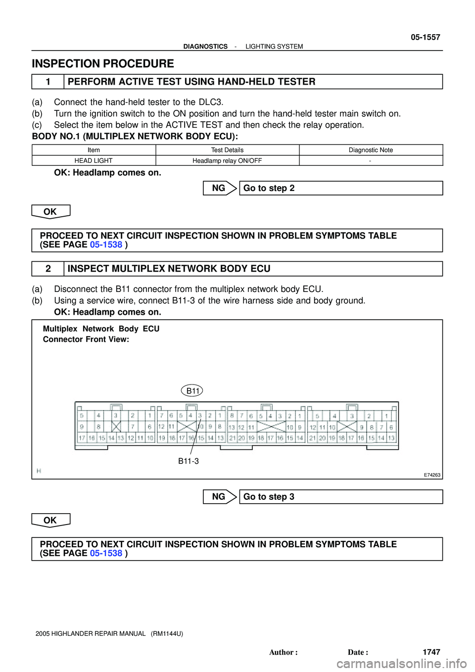
(a) Disconnect the B11 connector from the multiplex network body ECU.
(b) Using a service wire, connect B11-3 of the wire harness side and body ground.
OK: Headlamp comes on.
NG Go to step 3
OK
PROCEED TO NEXT CIRCUIT INSPECTION SHOWN IN PROBLEM SYMPTOMS TABLE
(SEE PAGE 05-1538)
Page 1533 of 2572
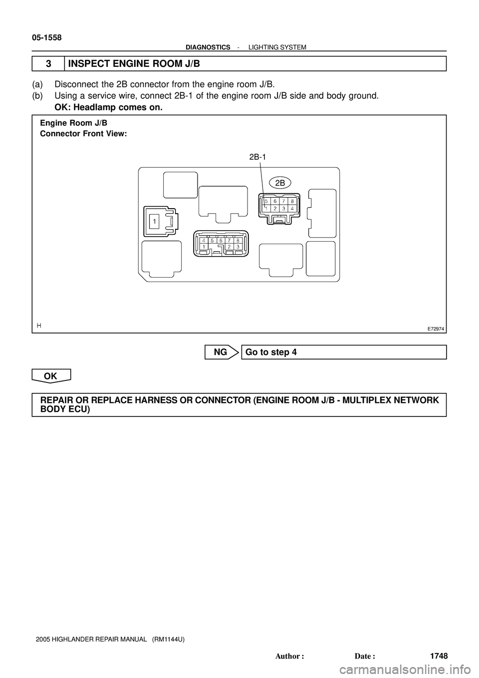
E72974
2B
2B-1 Engine Room J/B
Connector Front View:
05-1558
- DIAGNOSTICSLIGHTING SYSTEM
1748 Author�: Date�:
2005 HIGHLANDER REPAIR MANUAL (RM1144U)
3 INSPECT ENGINE ROOM J/B
(a) Disconnect the 2B connector from the engine room J/B.
(b) Using a service wire, connect 2B-1 of the engine room J/B side and body ground.
OK: Headlamp comes on.
NG Go to step 4
OK
REPAIR OR REPLACE HARNESS OR CONNECTOR (ENGINE ROOM J/B - MULTIPLEX NETWORK
BODY ECU)
Page 1538 of 2572
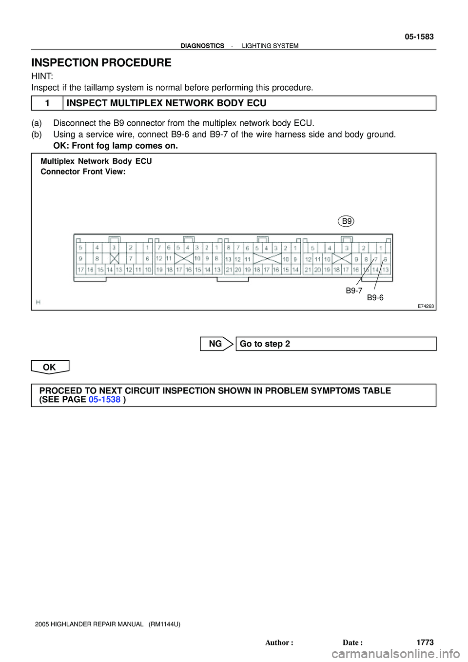
E74263
Multiplex Network Body ECU
Connector Front View:
B9
B9-7
B9-6
- DIAGNOSTICSLIGHTING SYSTEM
05-1583
1773 Author�: Date�:
2005 HIGHLANDER REPAIR MANUAL (RM1144U)
INSPECTION PROCEDURE
HINT:
Inspect if the taillamp system is normal before performing this procedure.
1 INSPECT MULTIPLEX NETWORK BODY ECU
(a) Disconnect the B9 connector from the multiplex network body ECU.
(b) Using a service wire, connect B9-6 and B9-7 of the wire harness side and body ground.
OK: Front fog lamp comes on.
NG Go to step 2
OK
PROCEED TO NEXT CIRCUIT INSPECTION SHOWN IN PROBLEM SYMPTOMS TABLE
(SEE PAGE 05-1538)
Page 1539 of 2572
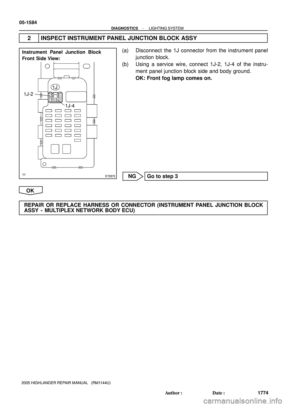
E72975
Instrument Panel Junction Block
Front Side View:
1J
1J-4 1J-2
05-1584
- DIAGNOSTICSLIGHTING SYSTEM
1774 Author�: Date�:
2005 HIGHLANDER REPAIR MANUAL (RM1144U)
2 INSPECT INSTRUMENT PANEL JUNCTION BLOCK ASSY
(a) Disconnect the 1J connector from the instrument panel
junction block.
(b) Using a service wire, connect 1J-2, 1J-4 of the instru-
ment panel junction block side and body ground.
OK: Front fog lamp comes on.
NG Go to step 3
OK
REPAIR OR REPLACE HARNESS OR CONNECTOR (INSTRUMENT PANEL JUNCTION BLOCK
ASSY - MULTIPLEX NETWORK BODY ECU)
Page 1772 of 2572
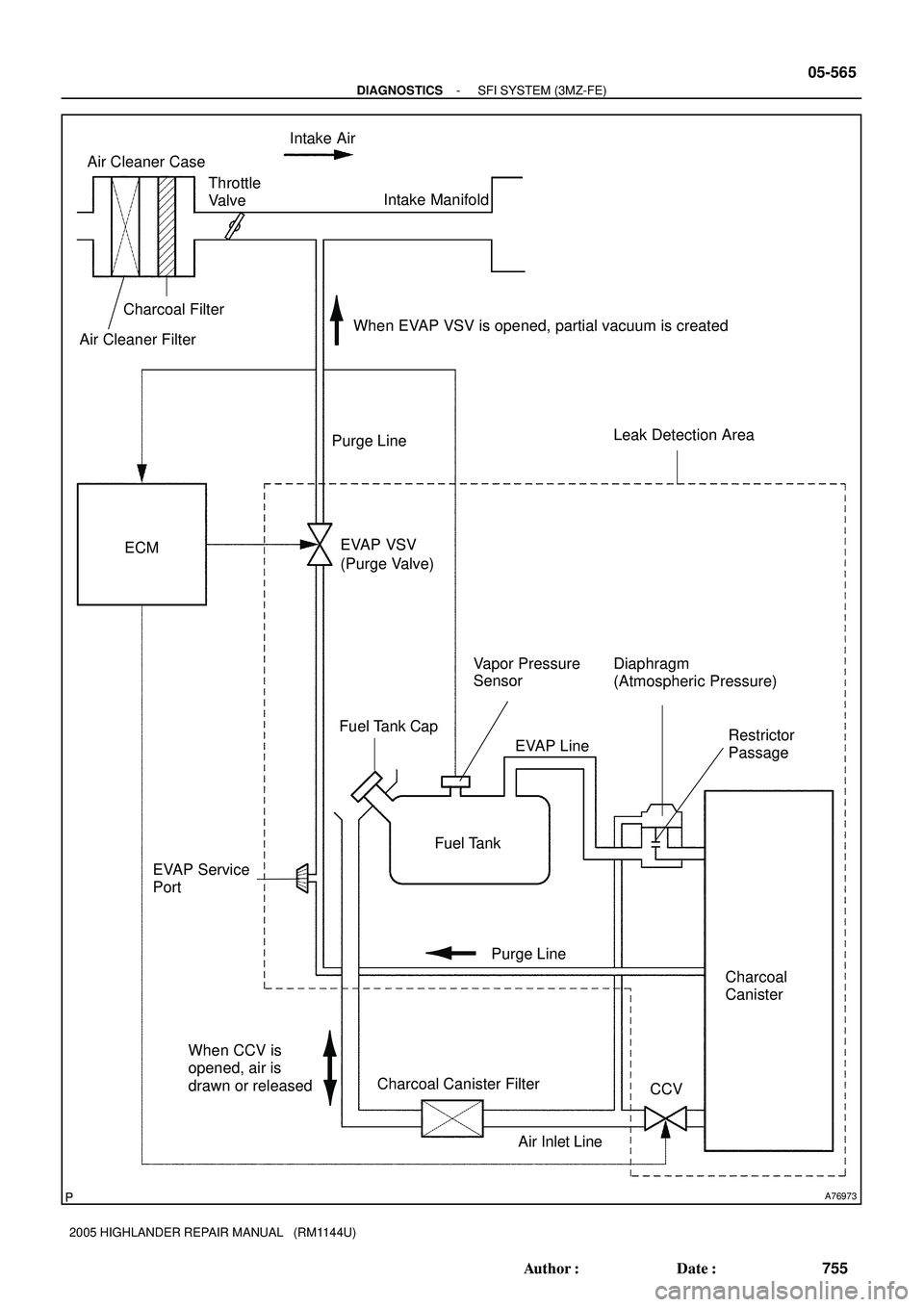
A76973
ECM
Fuel Tank
Charcoal
Canister EVAP VSV
Vapor Pressure
Sensor
CCV EVAP Service
PortIntake Air
Throttle
Valve
Fuel Tank Cap
Air Cleaner Case
Charcoal Canister Filter Charcoal Filter
Intake Manifold
Purge Line
Air Inlet Line EVAP Line Purge Line
Diaphragm
(Atmospheric Pressure)
Restrictor
Passage
When EVAP VSV is opened, partial vacuum is created
When CCV is
opened, air is
drawn or released
Leak Detection Area
(Purge Valve)
Air Cleaner Filter
- DIAGNOSTICSSFI SYSTEM (3MZ-FE)
05-565
755 Author�: Date�:
2005 HIGHLANDER REPAIR MANUAL (RM1144U)