Page 2425 of 2572
BODY PANEL REPLACEMENT
F12093
POINT
1 Cut the new part so that it overlaps the previous cut location by approximately 20 mm (0.79 in.).
2 Attach the weld bolt to center of the bearing surface.
PART NAME
[C] Rear Floor Side Panel Rear Extension
[E] Rear Floor Pan No.2 Extension
[H] Spare Wheel Carrier Bracket[D] Rear Floor Panel Extension
[F] Weld Bolt [G] Rear Floor Heat Insulator No.3 BracketBP-57
INSTALLATION
�Temporarily install the new parts and measure each part of the new parts in accordance with the body dimension
diagram. (See the body dimension diagram)
�Inspect the fitting of the related parts around the new parts before welding. This affects the appearance of the
finish.
�After welding, apply the polyurethane foam to the corresponding parts.
�After welding, apply body sealer and under-coating to the corresponding parts.
�After applying the top coat layer, apply anti-rust agent to the inside of the necked section structural weld spots.
Page 2450 of 2572
BODY PANEL REPLACEMENT
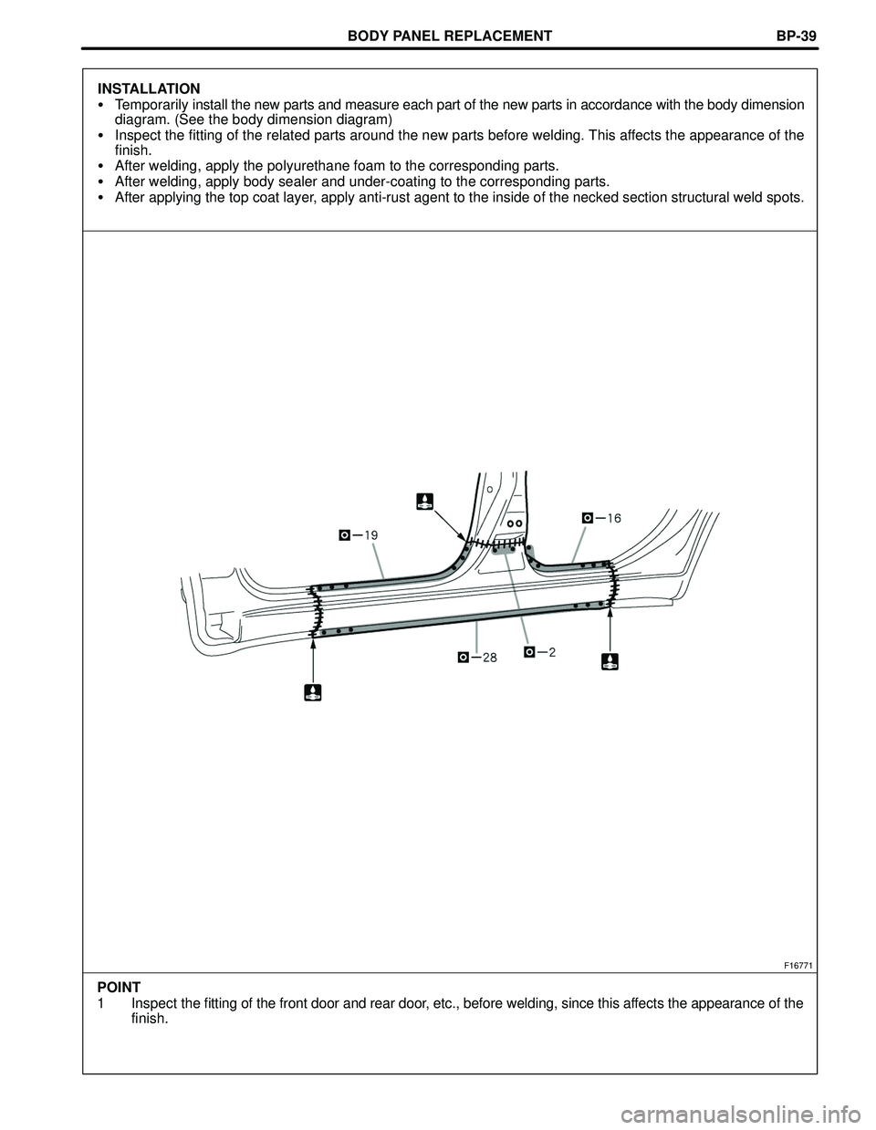
F16771
POINT
1 Inspect the fitting of the front door and rear door, etc., before welding, since this affects the appearance of the
finish.BP-39
INSTALLATION
�Temporarily install the new parts and measure each part of the new parts in accordance with the body dimension
diagram. (See the body dimension diagram)
�Inspect the fitting of the related parts around the new parts before welding. This affects the appearance of the
finish.
�After welding, apply the polyurethane foam to the corresponding parts.
�After welding, apply body sealer and under-coating to the corresponding parts.
�After applying the top coat layer, apply anti-rust agent to the inside of the necked section structural weld spots.
Page 2452 of 2572
BODY PANEL REPLACEMENT
F16730
POINT
1 Before temporarily installing the new parts, apply body sealer to the windshield header panel, roof panel rein-
forcement and back door opening frame.
HINT:
1) Apply just enough sealer for the new parts to make contact.
2 Bend the flange hem with a wooden hammer and dolly.
HINT:
1) Perform hemming three steps, being careful not to warp the panel.
BP-72
INSTALLATION
�Temporarily install the new parts and measure each part of the new parts in accordance with the body dimension
diagram. (See the body dimension diagram)
�Inspect the fitting of the related parts around the new parts before welding. This affects the appearance of the
finish.
�After welding, apply the polyurethane foam to the corresponding parts.
�After welding, apply body sealer and under-coating to the corresponding parts.
�After applying the top coat layer, apply anti-rust agent to the inside of the necked section structural weld spots.
Page 2454 of 2572
BODY PANEL REPLACEMENT
F16728
POINT
1 Before temporarily installing the new parts, apply body sealer to the windshield header panel, roof panel rein-
forcement and back door opening frame.
HINT:
1) Apply just enough sealer for the new parts to make contact.
BP-70
INSTALLATION
�Temporarily install the new parts and measure each part of the new parts in accordance with the body dimension
diagram. (See the body dimension diagram)
�Inspect the fitting of the related parts around the new parts before welding. This affects the appearance of the
finish.
�After welding, apply the polyurethane foam to the corresponding parts.
�After welding, apply body sealer and under-coating to the corresponding parts.
�After applying the top coat layer, apply anti-rust agent to the inside of the necked section structural weld spots.
Page 2456 of 2572
BODY PANEL REPLACEMENT
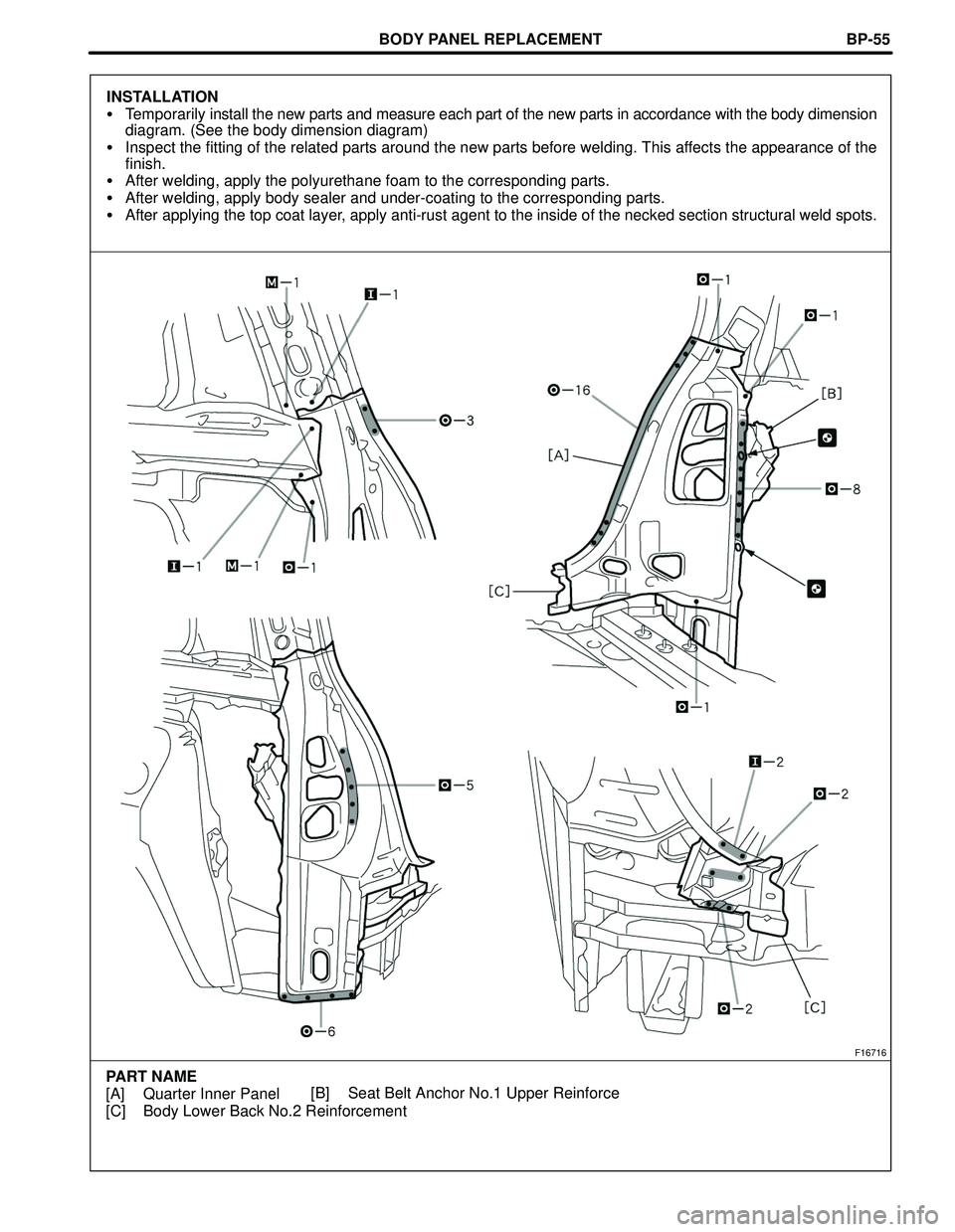
F16716
PART NAME
[A] Quarter Inner Panel
[C] Body Lower Back No.2 Reinforcement[B] Seat Belt Anchor No.1 Upper ReinforceBP-55
INSTALLATION
�Temporarily install the new parts and measure each part of the new parts in accordance with the body dimension
diagram. (See the body dimension diagram)
�Inspect the fitting of the related parts around the new parts before welding. This affects the appearance of the
finish.
�After welding, apply the polyurethane foam to the corresponding parts.
�After welding, apply body sealer and under-coating to the corresponding parts.
�After applying the top coat layer, apply anti-rust agent to the inside of the necked section structural weld spots.
Page 2524 of 2572

C83509
C50309
C50345C83655
Ring Gear Mounting
Case Plate Washer 31-24
- TRANSFERTRANSFER ASSY (4WD)
3102 Author�: Date�:
(f) Tighten the 7 bolts.
Torque: 28 NVm (286 kgfVcm, 21 ftVlbf)
57. INSPECT BACKLASH
(a) Set the dial indicator perpendicular to the ring gear face,
fix the driven pinion, and check backlash by moving the
ring gear.
Backlash: 0.10 to 0.15 mm (0.0039 to 0.0059 in.)
NOTICE:
Measure it at 3 points or more on the ring gear periphery.
(b) If the measured value is out of standard, select a proper
washer for the center differential case tapered roller bear-
ing on the LH side from the table below and install it to ob-
tain the standard value.
MarkWasher Thickness mm (in.)MarkWasher Thickness mm (in.)MarkWasher Thickness mm (in.)
AA2.07 (0.0814)AB2.10 (0.0826)AC2.13 (0.0838)
BA2.16 (0.0850)BB2.19 (0.0862)BC2.22 (0.0874)
CA2.25 (0.0885)CB2.28 (0.0897)CC2.31 (0.0909)
DA2.34 (0.0921)DB2.37 (0.0933)DC2.40 (0.0944)
EA2.43 (0.0956)EB2.46 (0.0968)EC2.49 (0.0980)
FA2.52 (0.0992)FB2.55 (0.1003)FC2.58 (0.1015)
GA2.61 (0.1027)GB2.64 (0.1039)GC2.67 (0.1051)
HA2.70 (0.1062)HB2.73 (0.1074)HC2.76 (0.1086)
JA2.79 (0.1098)JB2.82 (0.1110)JC2.85 (0.1122)
KA2.88 (0.1133)KB2.91 (0.1145)KC2.94 (0.1157)
LA2.97 (0.1169)LB3.00 (0.1181)
HINT:
When the backlash is larger or smaller than the standard, select
a thinner or thicker washer respectively.
(c) Ring gear mounting case plate washer location is shown
in the illustration.