Page 95 of 1897
AX03X-05
D07233
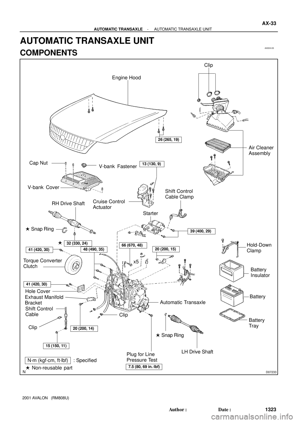
Engine Hood
Cruise Control
Actuator RH Drive ShaftAir Cleaner
Assembly
Shift Control
Cable
LH Drive Shaft
Plug for Line
Pressure TestBattery
TrayBatteryBattery
Insulator � Snap Ring
Exhaust Manifold
BracketHole Cover Torque Converter
ClutchShift Control
Cable Clamp
Starter
ClipHold-Down
Clamp
N´m (kgf´cm, ft´lbf) : Specified
� Non-reusable part� Snap Ring �
x5
26 (265, 19)
48 (490, 35)66 (670, 48)20 (200, 15)
15 (150, 11)
7.5 (80, 69 in.´lbf)
Automatic Transaxle
39 (400, 29)
20 (200, 14)
Clip
32 (330, 24)
13 (130, 9)Cap Nut
V-bank CoverV-bank Fastener
41 (420, 30)
41 (420, 30)
Clip
- AUTOMATIC TRANSAXLEAUTOMATIC TRANSAXLE UNIT
AX-33
1323 Author�: Date�:
2001 AVALON (RM808U)
AUTOMATIC TRANSAXLE UNIT
COMPONENTS
Page 100 of 1897
Q06530
Q10038
D07216
Q10037
- AUTOMATIC TRANSAXLEAUTOMATIC TRANSAXLE UNIT
AX-37
1327 Author�: Date�:
2001 AVALON (RM808U)
16. REMOVE EXHAUST MANIFOLD BRACKET MOUNT-
ING BOLT
Torque: 34 N´m (350 kgf´cm, 25 ft´lbf)
17. REMOVE 5 TRANSAXLE-TO-ENGINE BOLTS AND
DISCONNECT GROUND TERMINAL
Torque: 66 N´m (670 kgf´cm, 48 ft´lbf)
18. RAISE AND SUPPORT VEHICLE SECURELY
19. REMOVE LH AND RH FRONT WHEELS
Torque: 103 N´m (1,050 kgf´cm, 76 ft´lbf)
20. REMOVE DIFFERENTIAL FLUID DRAIN PLUG AND
GASKET
Torque: 49 N´m (500 kgf´cm, 36 ft´lbf)
HINT:
At the time of installation, please refer to the following item.
Replace the used gasket with a new gasket.
21. DRAIN DIFFERENTIAL FLUID
22. REMOVE LH AND RH FRONT DRIVE SHAFTS (See
page SA-16)
23. REMOVE ENGINE UNDER COVER
(a) Remove the 6 screws and turn over the front side of the
LH and RH fender liners.
(b) Remove the 2 screws and turn over the rear side of LH
and RH fender liners.
(c) Remove the engine under cover.
Page 109 of 1897
D07989
AX0KD-01
D07988
2
4
3
1
2
D07990
D07221
D07991
AX-24
- AUTOMATIC TRANSAXLEFLOOR SHIFT ASSEMBLY
1314 Author�: Date�:
2001 AVALON (RM808U)
DISASSEMBLY
1. REMOVE O/D MAIN SWITCH TERMINAL
(a) Remove the connector from the shift lever plate.
(b) Remove the secondary locking device.
(c) Release the looking lug of the terminals 2 and 4, and pull
the terminals out from the rear.
(d) Separate the O/D main switch wire harness from the 2
clamps.
2. REMOVE SHIFT LEVER KNOB SUB-ASSEMBLY
(a) Side the shift lever knob cover.
(b) Remove the 2 screws and shift lever knob sub-assembly.
NOTICE:
Pay attention not to apply unnatural load onto O/D main
switch wire harness.
3. DISASSEMBLE SHIFT LEVER KNOB
SUB-ASSEMBL Y
(a) Using a small screwdriver, remove the O/D main switch
cover.
(b) Using a small screwdriver, remove the O/D main switch
from the shift lever knob.
Page 122 of 1897
D07989
AX0KD-01
D07988
2
4
3
1
2
D07990
D07221
D07991
AX-24
- AUTOMATIC TRANSAXLEFLOOR SHIFT ASSEMBLY
1314 Author�: Date�:
2001 AVALON (RM808U)
DISASSEMBLY
1. REMOVE O/D MAIN SWITCH TERMINAL
(a) Remove the connector from the shift lever plate.
(b) Remove the secondary locking device.
(c) Release the looking lug of the terminals 2 and 4, and pull
the terminals out from the rear.
(d) Separate the O/D main switch wire harness from the 2
clamps.
2. REMOVE SHIFT LEVER KNOB SUB-ASSEMBLY
(a) Side the shift lever knob cover.
(b) Remove the 2 screws and shift lever knob sub-assembly.
NOTICE:
Pay attention not to apply unnatural load onto O/D main
switch wire harness.
3. DISASSEMBLE SHIFT LEVER KNOB
SUB-ASSEMBL Y
(a) Using a small screwdriver, remove the O/D main switch
cover.
(b) Using a small screwdriver, remove the O/D main switch
from the shift lever knob.
Page 144 of 1897

VALVE BODY ASSEMBLY
ON-VEHICLE REPAIR
1. CLEAN TRANSAXLE EXTER")
AX05D-03
AT3785
AT0103
D01019
Q05728
Connector AX-6
- AUTOMATIC TRANSAXLEVALVE BODY ASSEMBLY
1296 Author�: Date�:
2001 AVALON (RM808U)
VALVE BODY ASSEMBLY
ON-VEHICLE REPAIR
1. CLEAN TRANSAXLE EXTERIOR
To help prevent contamination, clean the exterior of the trans-
axle.
2. DRAIN ATF
Using a hexagon wrench, remove the drain plug and drain the
fluid into the suitable container.
3. REMOVE OIL PAN AND GASKET
NOTICE:
Some fluid will remain in the oil pan.
Remove oil pan bolts, and carefully remove the pan assembly.
Discard the gasket.
4. EXAMINE PARTICLES IN PAN
Remove the magnets and use them to collect any steel chips.
Look at the chips and particles in the pan and magnet carefully
to anticipate what type of wear you will find in the transaxle.
�Steel (magnetic): bearing, gear and plate wear
�Brass (non-magnetic): bushing wear
5. REMOVE OIL STRAINER AND APPLY PIPE BRACKET
(a) Remove the 3 bolts and oil strainer.
NOTICE:
Be careful as oil will come out of the strainer when it is re-
moved.
(b) Remove the 3 bolts and apply pipe bracket.
6. REMOVE OIL PIPE
Pry up both pipe ends with a large screwdriver and remove the
5 pipes.
7. DISCONNECT 3 SOLENOID CONNECTORS
Page 149 of 1897
Z19256
BA
B A
AT3741
AT3785
- AUTOMATIC TRANSAXLEVALVE BODY ASSEMBLY
AX-1 1
1301 Author�: Date�:
2001 AVALON (RM808U)
24. INSTALL OIL STRAINER AND APPLY PIPE BRACKET
Install the oil strainer and apply pipe bracket with the 6 bolts.
Torque:
Bolt A: 10 N´m (100 kgf´cm, 7 ft´lbf)
Bolt B: 11 N´m (110 kgf´cm, 8 ft´lbf)
Bolt length:
Bolt A: 22 mm (0.866 in.)
Bolt B: 53 mm (2.087 in.)
25. INSTALL MAGNET IN PLACE
Install the 3 magnets in the indentations of the oil pan, as shown
in the illustration.
NOTICE:
Make sure that the magnet does not interfere with the oil
pipes.
26. INSTALL OIL PAN AND GASKET
(a) Install the oil pan and a new gasket.
(b) Install the 17 bolts.
Torque: 7.8 N´m (80 kgf´cm, 69 in.´lbf)
27. INSTALL DRAIN PLUG
Install a new gasket and drain plug.
Torque: 49 N´m (500 kgf´cm, 36 ft´lbf)
28. FILL ATF AND CHECK FLUID LEVEL
(See page DI-160)
Page 162 of 1897

I19691
ºTUNE DOWNº Switch
º1chº Switch º2chº Switch º3chº Switchº4chº Switch º5chº Switchº6chº Switch
ºDISCº Switch
ºTUNE UPº Switch
- BODY ELECTRICALAUDIO SYSTEM
BE-133
1737 Author�: Date�:
2001 AVALON (RM808U)
2. Except Europe models:
DIAGNOSIS FUNCTION
Error codes over tuner and connected equipment are displayed on the screen of tuner.
(a) Diagnosis start-up
For shifting to diagnosis mode, push ºDISCº switch 3 times with pressing º1º and º6º of PRESET switch
at the same time while the audio power is OFF and ACC is ON.
To exit from diagnosis mode, press ºDISCº switch for 2 seconds or turn the ignition key OFF.
(When º1-190º is displayed, the mode is transferred to LAN check mode.)
(b) LAN check
When starting up the diagnosis mode, the mode turns to LAN check mode, the screen displays the
code numbers (physical address) of tuner and connected equipment. Smaller codes are displayed in
order, displayed code numbers are switched by operating TUNE ºUPº or ºDOWNº switch. In LAN check
mode, by pressing º5º of PRESET switch for more than 2 secs., diagnosis memory of each equipment
can be deleted, when deletion is completed, the mode returns to LAN check mode.
Code No. (physical address) List
Code No. (physical address)Equipment name
190Radio receiver assembly (Audio head unit)
240CD changer (in Luggage room)
360CD changer (in center console and glove compartment box)
440Power amplifier
(c) System check
�When pressing º1º of PRESET switch in LAN check mode, the mode turns to the system check
mode, the system performs self diagnosis of connected equipment and displays the re-
sults.(ºSYSº (showing the system is under detection) is displayed.)
�Perform the operation shown in the following illustration, then read the result of the inspection.
Page 175 of 1897

Check if there is any scratch and br")
6RadioPOOR RECEPTION
Is the condition bad in comparison with other vehicles?
Are there any additional installation parts?
(Sun shade film, telephone antenna, etc.)
Check if there is any scratch and breaking of a wire on
the glass antenna and the defogger pattern.
(visual check. tester)
(See page BE-126)
Is the contact of the plug jack of the radio OK?
Does the condition get better by using the outer
antenna (such as pillar antenna)?
Is the contact of the antenna terminal on the glass
surface and the defogger terminal?
Is the continuity of the antenna cord OK?
Check the grounding of the antenna, antenna cord,
choke coil, and noise filter. (See page BE-126)
Does the condition get better by replacing
the choke coil?
Does the condition get better by replacing the
antenna cord?Take a measure for contact. An electric wave environment is bad.
Does the condition get better if
removing them?
Influence of additional installation parts.
Repair. (See Pub. No. RM588E on
page BE-125)
Check the radio.
Take a measure for contact.
Grounding failure. Replace the antenna cord.
Replace the choke coil.
Replace the antenna cord. Ye s
No
Exchange the glass.Ye s
Ye s
Ye s
Ye s
Ye s
Ye s
Ye s
Ye s No
No
No
NoNo
No
No
No
NG
OK
Ye s BE-146
- BODY ELECTRICALAUDIO SYSTEM
1750 Author�: Date�:
2001 AVALON (RM808U)