Page 1450 of 1897

REPLACEMENT
CAUTION:
�Prolonged and repeated contact with miner")
LU01Q-03
B06524
B06486
SST
B06479
SST
Additional
3/4 Turn
- LUBRICATIONOIL AND FILTER
LU-3
1228 Author�: Date�:
2001 AVALON (RM808U)
REPLACEMENT
CAUTION:
�Prolonged and repeated contact with mineral oil will
result in the removal of natural fats from the skin,
leading to dryness, irritation and dermatitis. In addi-
tion, used engine oil contains potentially harmful
contaminants which may cause skin cancer.
�Exercise caution in order to minimize the length and
frequency of contact of your skin to used oil. Wear
protective clothing and gloves. Wash your skin thor-
oughly with soap and water, or use water-less hand
cleaner, to remove any used engine oil. Do not use
gasoline, thinners, or solvents.
�In order to preserve the environment, used oil and
used oil filter must be disposed of only at designated
disposal sites.
1. DRAIN ENGINE OIL
(a) Remove the oil filler cap.
(b) Remove the oil drain plug, and drain the oil into a contain-
er.
2. REPLACE OIL FILTER
(a) Using SST, remove the oil filter.
SST 09228-07501
(b) Check and clean the oil filter installation surface.
(c) Apply clean engine oil to the gasket of a new oil filter.
(d) Lightly screw the oil filter into place, and tighten it until the
gasket contacts the seat.
(e) Using SST, tighten it an additional 3/4 turn.
SST 09228-07501
Page 1451 of 1897
LU-4
- LUBRICATIONOIL AND FILTER
1229 Author�: Date�:
2001 AVALON (RM808U)
3. REFILL WITH ENGINE OIL
(a) Clean and install the oil drain plug with a new gasket.
Torque: 45 N´m (460 kgf´cm, 33 ft´lbf)
(b) Fill with fresh engine oil.
Capacity:
Drain and refill w/ Oilfilter change
w/o Oilfilter change4.7 liters (5.0 US qts, 4.1 lmp. qts)
4.5 liters (4.8 US qts, 4.0 lmp. qts)
Dry fill5.2 liters (5.5 US qts, 4.6 lmp. qts)
(c) Install the oil filler cap.
4. START ENGINE AND CHECK FOR OIL LEAKS
5. RECHECK ENGINE OIL LEVEL
Page 1452 of 1897
LU01R-04
B09034
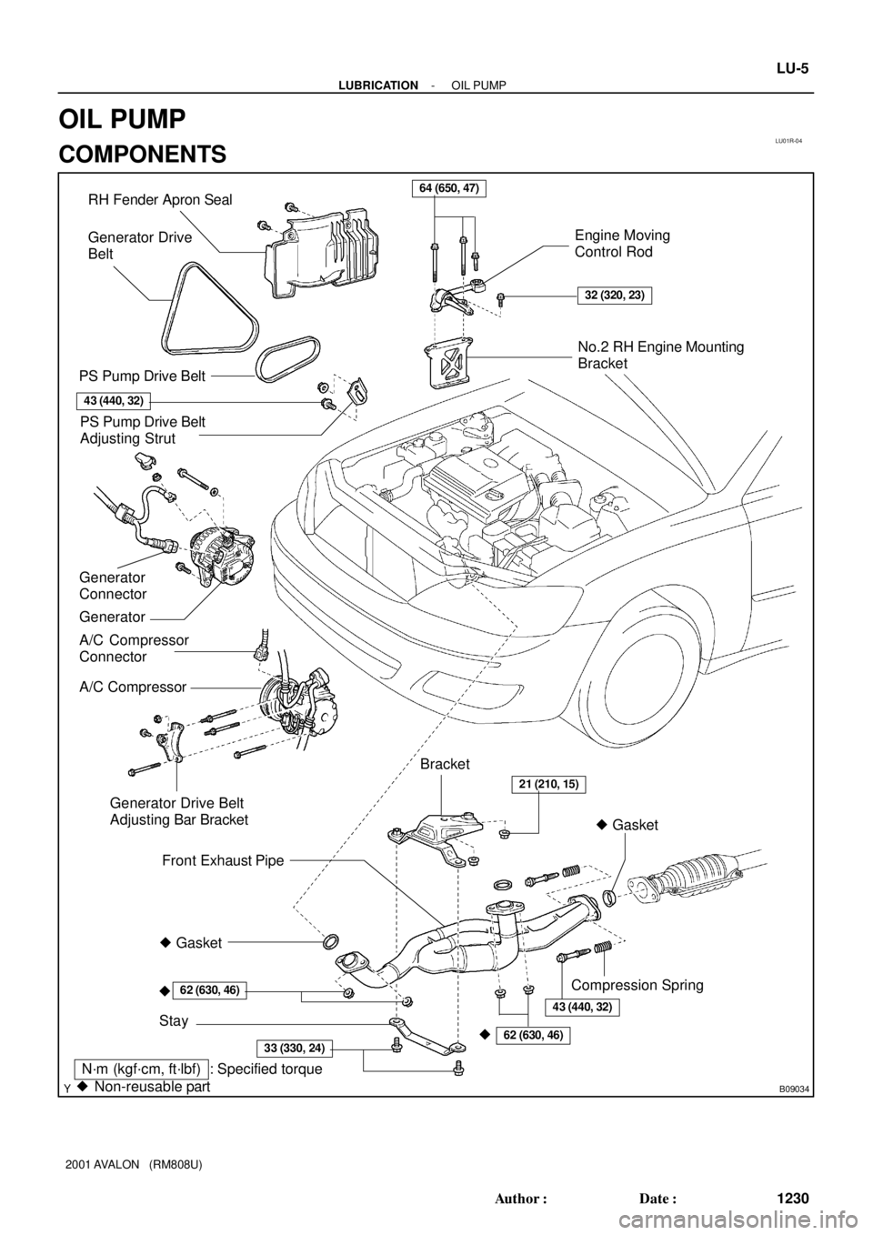
� Gasket RH Fender Apron Seal
PS Pump Drive Belt
A/C Compressor
Connector
A/C CompressorEngine Moving
Control Rod
No.2 RH Engine Mounting
Bracket
Front Exhaust Pipe
Stay
�
PS Pump Drive Belt
Adjusting Strut
Generator Drive Belt
Adjusting Bar Bracket
� Gasket
�
62 (630, 46)
33 (330, 24)
21 (210, 15)
64 (650, 47)
32 (320, 23)
62 (630, 46)
N´m (kgf´cm, ft´lbf) : Specified torque
� Non-reusable partBracket Generator Drive
Belt
43 (440, 32)
Compression Spring
Generator Generator
Connector
43 (440, 32)
- LUBRICATIONOIL PUMP
LU-5
1230 Author�: Date�:
2001 AVALON (RM808U)
OIL PUMP
COMPONENTS
Page 1453 of 1897
B06519
B08672
No.2 Timing Belt CoverTiming Belt
Timing Belt Guide
No.2 Generator
Bracket RH Engine Mounting Bracket
Crankshaft
PulleyGasket
Engine Wire
Protector
RH Camshaft Timing Pulley
No.2 Idler Pulley
Crankshaft
Timing PulleyDust Boot
Timing Belt Plate Plate Washer
�
215 (2,200, 159)
43 (440, 32)
27 (280, 20)
Timing Belt TensionerN´m (kgf´cm, ft´lbf) : Specified torque
� Non-reusable part
28 (290, 21)
No.1 Timing Belt Cover
125 (1,300, 94)
*88 (900, 65)
LH Camshaft
Timing Pulley
No.1 Idler Pulley
34 (350, 25)
� Precoated part
* For use with SST
125 (1,300, 94)
LU-6
- LUBRICATIONOIL PUMP
1231 Author�: Date�:
2001 AVALON (RM808U)
Page 1454 of 1897
B08905
N´m (kgf´cm, ft´lbf): Specified torque
� Non-reusable partNo.3 Timing Belt Cover
Gasket
BushingCollar
A/C Compressor
Housing Bracket
Oil Pan Baffle Plate Crankshaft
Position Sensor
Connector Crankshaft
Position
Sensor
Oil PumpEngine Wire
Oil Strainer
No.2 Oil Pan
x 10x 6
x 9� O-Ring
No.1 Oil Pan
� Gasket
Drain Plug
8.5 (85, 74 in.´lbf)
8 (80, 69 in.´lbf)
8 (80, 69 in.´lbf)
10 mm Head 8 (80, 69 in.´lbf)
12 mm Head 19.5 (200, 14)
10 mm Head 8 (80, 69 in.´lbf)
12 mm Head 19.5 (200, 14)
14 mm Head 37.2 (380, 27)
8 (80, 69 in.´lbf)
45 (460, 33)
8 (80, 69 in.´lbf)
x 6
x 17
� Gasket
19.5 (200, 14)
No.1 Exhaust Pipe
Support Bracket
- LUBRICATIONOIL PUMP
LU-7
1232 Author�: Date�:
2001 AVALON (RM808U)
Page 1457 of 1897

INSPECTION
1. INSPECT RELIEF VALVE
Coat the valve with engine oil and check tha")
LU01U-03
B04140
B04141
Mark
B04142
B04143
B04144
LU-12
- LUBRICATIONOIL PUMP
1237 Author�: Date�:
2001 AVALON (RM808U)
INSPECTION
1. INSPECT RELIEF VALVE
Coat the valve with engine oil and check that it falls smoothly
into the valve hole by its own weight.
If it does not, replace the relief valve. If necessary, replace the
oil pump assembly.
2. PLACE DRIVE AND DRIVEN ROTORS INTO OIL PUMP
BODY
Place the drive and driven rotors into the oil pump body with the
mark facing upward.
3. INSPECT ROTOR SIDE CLEARANCE
Using a feeler gauge and precision straight edge, measure the
clearance between the rotors and precision straight edge.
Standard side clearance:
0.030 - 0.090 mm (0.0012 - 0.0035 in.)
Maximum side clearance: 0.15 mm (0.0059 in.)
If the side clearance is greater than maximum, replace the ro-
tors as a set. If necessary, replace the oil pump assembly.
4. INSPECT ROTOR TIP CLEARANCE
Using a feeler gauge, measure the clearance between the drive
and driven rotor tips.
Standard tip clearance:
0.110 - 0.240 mm (0.0043 - 0.0094 in.)
Maximum tip clearance: 0.35 mm (0.0138 in.)
If the tip clearance is greater than maximum, replace the rotors
as a set.
5. INSPECT ROTOR BODY CLEARANCE
Using a feeler gauge, measure the clearance between the driv-
en rotor and body.
Standard body clearance:
0.250 - 0.325 mm (0.0098 - 0.0128 in.)
Maximum body clearance: 0.40 mm (0.0157 in.)
If the body clearance is greater than maximum, replace the ro-
tors as a set. If necessary, replace the oil pump assembly.
Page 1461 of 1897
LU-18
- LUBRICATIONOIL PUMP
1243 Author�: Date�:
2001 AVALON (RM808U)
9. INSTALL ADJUSTING STRUT AND PS PUMP DRIVE
BELT
(a) Temporarily install the adjusting strut with the bolt and nut.
(b) Install the drive belt with the pivot and adjusting bolts.
Torque: 43.1 N´m (440 kgf´cm, 32 ft´lbf)
(c) Tighten the nut.
Torque: 43.1 N´m (440 kgf´cm, 32 ft´lbf)
10. INSTALL A/C COMPRESSOR (See page EM-77)
11. INSTALL GENERATOR (See page CH-1)
12. INSTALL RH FENDER APRON SEAL
13. INSTALL FRONT EXHAUST PIPE (See page EM-77)
14. INSTALL RH FRONT WHEEL
15. FILL ENGINE WITH OIL
16. START ENGINE AND CHECK FOR LEAKS
17. RECHECK ENGINE OIL LEVEL
Page 1463 of 1897
LU0IB-01
P18778
Pivot
Bolt
Adjusting
Strut
Adjusting Bolt
B04135
P18801
- LUBRICATIONOIL PUMP
LU-9
1234 Author�: Date�:
2001 AVALON (RM808U)
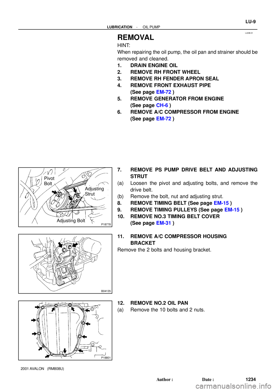
REMOVAL
HINT:
When repairing the oil pump, the oil pan and strainer should be
removed and cleaned.
1. DRAIN ENGINE OIL
2. REMOVE RH FRONT WHEEL
3. REMOVE RH FENDER APRON SEAL
4. REMOVE FRONT EXHAUST PIPE
(See page EM-72)
5. REMOVE GENERATOR FROM ENGINE
(See page CH-6)
6. REMOVE A/C COMPRESSOR FROM ENGINE
(See page EM-72)
7. REMOVE PS PUMP DRIVE BELT AND ADJUSTING
STRUT
(a) Loosen the pivot and adjusting bolts, and remove the
drive belt.
(b) Remove the bolt, nut and adjusting strut.
8. REMOVE TIMING BELT (See page EM-15)
9. REMOVE TIMING PULLEYS (See page EM-15)
10. REMOVE NO.3 TIMING BELT COVER
(See page EM-31)
11. REMOVE A/C COMPRESSOR HOUSING
BRACKET
Remove the 2 bolts and housing bracket.
12. REMOVE NO.2 OIL PAN
(a) Remove the 10 bolts and 2 nuts.