Page 1794 of 1897
W03098
SST Rack Guide
Spring Cap
W03099
12°
W03100
SST
W03101
SST
Rack Guide
Spring CapSST SR-52
- STEERINGPOWER STEERING GEAR
1515 Author�: Date�:
2001 AVALON (RM808U)
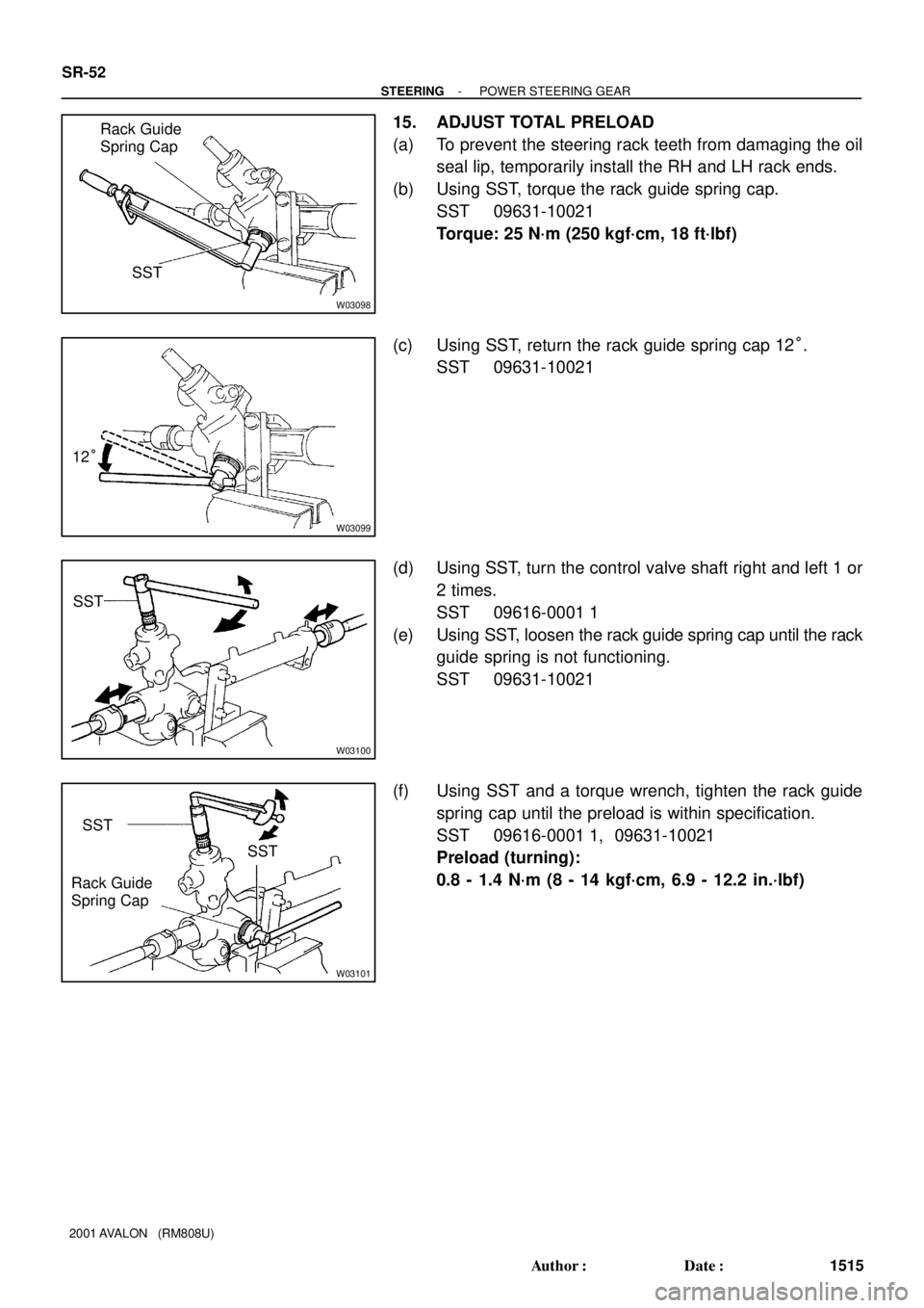
15. ADJUST TOTAL PRELOAD
(a) To prevent the steering rack teeth from damaging the oil
seal lip, temporarily install the RH and LH rack ends.
(b) Using SST, torque the rack guide spring cap.
SST 09631-10021
Torque: 25 N´m (250 kgf´cm, 18 ft´lbf)
(c) Using SST, return the rack guide spring cap 12°.
SST 09631-10021
(d) Using SST, turn the control valve shaft right and left 1 or
2 times.
SST 09616-0001 1
(e) Using SST, loosen the rack guide spring cap until the rack
guide spring is not functioning.
SST 09631-10021
(f) Using SST and a torque wrench, tighten the rack guide
spring cap until the preload is within specification.
SST 09616-0001 1, 09631-10021
Preload (turning):
0.8 - 1.4 N´m (8 - 14 kgf´cm, 6.9 - 12.2 in.´lbf)
Page 1795 of 1897

16. INSTALL RACK GUIDE")
W03102
SSTRack Guide
Spring Cap
Lock Nut
SST Fulcrum
Length
R11667
Claw
F03861
Fulcrum
Length
SST
- STEERINGPOWER STEERING GEAR
SR-53
1516 Author�: Date�:
2001 AVALON (RM808U)
16. INSTALL RACK GUIDE SPRING CAP LOCK NUT
(a) Apply sealant to 2 or 3 threads of the rack guide spring
cap lock nut.
Sealant:
Part No.08833-00080, THREE BOND 1344,
LOCTITE 242 or equivalent
(b) Temporarily install the rack guide spring cap lock nut.
(c) Using SST, hold the rack guide spring cap and using
another SST torque the rack guide spring cap lock nut.
SST 09631-10021, 09922-10010
Torque: 50 N´m (510 kgf´cm, 37 ft´lbf)
NOTICE:
Use SST 09922-10010 in the direction shown in the illustra-
tion.
HINT:
Use a torque wrench with a fulcrum length of 345 mm (13.58
in.).
(d) Recheck the total preload.
Preload (turning):
0.8 - 1.4 N´m (8 - 14 kgf´cm, 6.9 - 12.2 in.´lbf)
(e) Remove the RH and LH rack ends.
17. INSTALL RH AND LH CLAW WASHERS AND RACK
ENDS
(a) Install a new claw washer, and temporarily install the rack
ends.
HINT:
Align the claws of the claw washers with the steering rack
grooves.
(b) Using a spanner (24 mm), hold the steering rack steadily
and using SST, torque the rack end.
SST 09922-10010
Torque: 60 N´m (610 kgf´cm, 44 ft´lbf)
NOTICE:
Use SST 09922-10010 in the direction shown in the illustra-
tion.
HINT:
Use a torque wrench with a fulcrum length of 345 mm (13.58
in.).
Page 1796 of 1897

or less
SST
R00429
Matchmarks SR-54
- STEERINGPOWER STEERING GEAR
1517 Author�: Date�:
2001 AVALON (RM808U)
(c) Using a brass bar and hammer, stake the")
R11668
Brass Bar
R11669
W04223
2 mm
(0.79 in.)
or less
SST
R00429
Matchmarks SR-54
- STEERINGPOWER STEERING GEAR
1517 Author�: Date�:
2001 AVALON (RM808U)
(c) Using a brass bar and hammer, stake the claw washer.
NOTICE:
Avoid any impact on the steering rack.
(d) Employ the same manner described above to the other
side.
18. INSTALL RH AND LH RACK BOOTS, CLAMPS AND
CLIPS
(a) Ensure that the steering rack hole is not clogged with
grease.
HINT:
If the hole is clogged, the pressure inside the rack boot will
change after it is assembled and the steering wheel is turned.
(b) Install the rack boot, clip and a new clamp.
NOTICE:
Be careful not to damage or twist the rack boot.
(c) Using SST, tighten the clamp as shown in the illustration.
SST 09521-24010
(d) Employ the same manner described above to the other
side.
19. INSTALL RH AND LH TIE ROD ENDS AND LOCK NUTS
(a) Screw the lock nut and tie rod end onto the rack end until
the matchmarks are aligned.
(b) After adjusting toe-in, torque the lock nut (See page
SA-4).
Torque: 74 N´m (750 kgf´cm, 54 ft´lbf)
(c) Employ the same manner described above to the other
side.
Page 1797 of 1897
F13588SST
Fulcrum
Length
- STEERINGPOWER STEERING GEAR
SR-55
1518 Author�: Date�:
2001 AVALON (RM808U)
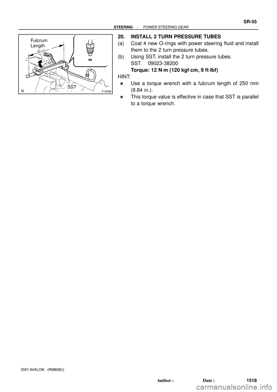
20. INSTALL 2 TURN PRESSURE TUBES
(a) Coat 4 new O-rings with power steering fluid and install
them to the 2 turn pressure tubes.
(b) Using SST, install the 2 turn pressure tubes.
SST 09023-38200
Torque: 12 N´m (120 kgf´cm, 9 ft´lbf)
HINT:
�Use a torque wrench with a fulcrum length of 250 mm
(9.84 in.).
�This torque value is effective in case that SST is parallel
to a torque wrench.
Page 1798 of 1897

REMOVAL
NOTICE:
Remove the steering wheel assembly before the steering
gear removal, because there i")
SR0EU-05
F13586
SST
SR-40
- STEERINGPOWER STEERING GEAR
1503 Author�: Date�:
2001 AVALON (RM808U)
REMOVAL
NOTICE:
Remove the steering wheel assembly before the steering
gear removal, because there is possibility of breaking of
the spiral cable.
1. PLACE FRONT WHEELS FACING STRAIGHT AHEAD
2. REMOVE STEERING WHEEL PAD (See page SR-12)
3. REMOVE STEERING WHEEL (See page SR-12)
4. DISCONNECT RH AND LH TIE ROD ENDS (See page
SA-9)
5. DISCONNECT INTERMEDIATE SHAFT SUB- AS-
SEMBLY (See page SR-12)
6. DISCONNECT CLAMP PLATE
Remove the nut and clamp plate.
7. DISCONNECT PRESSURE FEED AND RETURN
TUBES
(a) Using SST, disconnect the pressure feed and return
tubes.
SST 09023-38400
(b) Remove the 2 O-rings from the pressure feed and return
tubes.
8. DISCONNECT STABILIZER BAR
Remove the 4 bolts and disconnect the stabilizer bar.
HINT:
Do not remove the stabilizer bar.
9. REMOVE NO. 1 FUEL TUBE PROTECTOR
Remove the 2 bolts, nut and No. 1 fuel tube protector.
10. REMOVE PS GEAR ASSEMBLY
(a) Remove the 2 PS gear assembly set bolts and nuts.
HINT:
Lift up the stabilizer bar and remove the bolts.
(b) Remove the PS gear assembly from the LH of the vehicle.
NOTICE:
Do not damage the turn pressure tubes.
Page 1799 of 1897

SR0RX-02
F01792
Press
SST
Oil Seal
Bearing
W03560
Press
SST
Oil SealSST
F03877
PressSST
SST Bearing
F01794
Brass Bar
Bearing
F01795
Press
SST
Bearing
SR-46
- STEERINGPOWER STEERING GEAR
1509 Author�: Date�:
2001 AVALON (RM808U)
REPLACEMENT
NOTICE:
When using a vise, do not over tighten it.
1. IF NECESSARY, REPLACE OIL SEAL AND BEARING
(a) Using SST, press out the oil seal and bearing from the
control valve housing.
SST 09950-60010 (09951-00250),
09950-70010 (09951-07200)
(b) Coat a new oil seal lip with power steering fluid.
(c) Using SST, press in the oil seal.
SST 09950-60010 (09951-00180, 09951-00320,
09952-06010), 09950-70010 (09951-07200)
NOTICE:
Make sure that the oil seal is installed facing in the correct
direction.
(d) Coat a new bearing with molybdenum disulfide lithium
base grease.
(e) Using SST, press in the bearing.
SST 09950-60010 (09951-00180, 09951-00340,
09952-06010), 09950-70010 (09951-07200)
2. IF NECESSARY, REPLACE 2 BEARINGS
(a) Using a brass bar and hammer, tap out the bearing from
the rack housing.
(b) Using SST, press out the bearing from the rack housing.
SST 09950-60010 (09951-00260),
09950-70010 (09951-07200)
Page 1800 of 1897
")
F03878
PressSST
SST
Bearing
F01797
Press
SST
Bearing
F01798SST
BushingOil
Seal
SST
F03863
Press
Oil Seal
SST
SST
R10955
- STEERINGPOWER STEERING GEAR
SR-47
1510 Author�: Date�:
2001 AVALON (RM808U)
(c) Coat a new bearing with molybdenum disulfide lithium
base grease.
(d) Using SST, press in the bearing.
SST 09950-60010 (09951-00250, 09951-00310,
09952-06010), 09950-70010 (09951-07200)
(e) Coat a new bearing with molybdenum disulfide lithium
base grease.
(f) Using SST, press in the bearing.
SST 09950-60010 (09951-00320),
09950-70010 (09951-07200)
3. IF NECESSARY, REPLACE OIL SEAL
(a) Using SST, remove the oil seal from the bushing.
SST 09527-2001 1, 09612-24014 (09613-22011)
NOTICE:
Be careful not to damage the bushing.
(b) Coat a new oil seal lip with power steering fluid.
(c) Using SST, press in the oil seal.
SST 09950-60010 (09951-00240, 09951-00400,
09952-06010)
NOTICE:
Make sure that the oil seal is installed facing in the correct
direction.
4. IF NECESSARY, REPLACE TEFLON RING AND O-
RING
(a) Using a screwdriver, remove the teflon ring and O-ring
from the steering rack.
NOTICE:
Be careful not to damage the groove for the teflon ring.
(b) Coat a new O-ring with power steering fluid and install it.
Page 1801 of 1897

(c) Expand a new teflon ring with your fingers.
NOTICE:
Be care")
R06172
N00401
R11572
Teflon Ring
R11573
SST
Teflon Ring SR-48
- STEERINGPOWER STEERING GEAR
1511 Author�: Date�:
2001 AVALON (RM808U)
(c) Expand a new teflon ring with your fingers.
NOTICE:
Be careful not to over expand the ring.
(d) Coat the teflon ring with power steering fluid.
(e) Install the teflon ring to the steering rack, and settle it
down with your fingers.
5. IF NECESSARY, REPLACE 4 TEFLON RINGS
(a) Using a screwdriver, remove the 4 teflon rings from the
control valve assembly.
NOTICE:
Be careful not to damage the grooves for the teflon ring.
(b) Expand 4 new teflon rings with your fingers.
NOTICE:
Be careful not to over expand the teflon ring.
(c) Coat the teflon rings with power steering fluid.
(d) Install the teflon rings to the control valve assembly, and
settle them down with your fingers.
(e) Carefully slide the tapered end of SST over the teflon
rings until the teflon rings fit to the control valve assembly.
SST 09631-20081
NOTICE:
Be careful not to damage the teflon rings.