Page 967 of 1897
 (+)
ON
OFF
VSV for CCV
Measure
Voltage30 sec.
DI-88
- DIAGNOSTICSENGINE
244 Author�: Date�:
2001 AVALO")
A10620A10574A11937
ON
VSV for pressure
Switching Valve
OFF
VSV for EVAP
1.2 V ON
OFF
E2
PTNK (-) (+)
ON
OFF
VSV for CCV
Measure
Voltage30 sec.
DI-88
- DIAGNOSTICSENGINE
244 Author�: Date�:
2001 AVALON (RM808U)
NG Repair or replace harness or connector.
OK
Check and replace ECM (See page IN-30).
24 Check fuel tank.
PREPARATION:
(a) Remove the grove compartment (See page SF-82).
(b) Connect the TOYOTA hand-held tester to the DLC3.
(c) Select the ACTIVE TEST mode on the TOYOTA hand-
held tester.
(d) Start the engine.
(e) The VSV for the CCV is ON by the TOYOTA hand-held
tester.
(f) The VSV for the EVAP and the VSV for the pressure
switching valve are ON by the TOYOTA hand-held tester
and hold the VSV for the EVAP until voltage between ter-
minals PTNK and E2 becomes 1.2 V.
CHECK:
Measure the voltage between terminals PTNK and E2 of the
ECM connectors 30 sec. after switching the VSV for the EVAP
and the VSV for the pressure switching valve from ON to OFF.
OK:
Voltage:
When there is no sharp change of the voltage with the
voltage of more or less 1.2 V
NG Replace fuel tank.
OK
Page 968 of 1897
 (+)
ON
OFF VSV for pressure
Switching Valve VSV for EVAP
VSV for CCV
1.2 V Measure
Voltage30 sec.
- DIAGNOSTICSENGINE
DI-89
245 Author�: Date�:
2001 AVAL")
A10574 A10621A11938 ON
OFF
ON
OFF
E2
PTNK (-) (+)
ON
OFF VSV for pressure
Switching Valve VSV for EVAP
VSV for CCV
1.2 V Measure
Voltage30 sec.
- DIAGNOSTICSENGINE
DI-89
245 Author�: Date�:
2001 AVALON (RM808U)
25 Check charcoal canister.
PREPARATION:
(a) Remove the grove compartment (See page SF-82).
(b) Connect the TOYOTA hand-held tester to the DLC3.
(c) Select the ACTIVE TEST mode on the TOYOTA hand-
held tester.
(d) Start the engine.
(e) The VSV for the CCV and the VSV for the pressure
switching valve are ON by the TOYOTA hand-held tester.
(f) The VSV for the EVAP is ON by the TOYOTA hand-held
tester and hold the VSV for the EVAP until voltage be-
tween terminals PTNK and E2 becomes 1.2 V.
CHECK:
Measure the voltage between terminals PTNK and E2 of the
ECM connectors 30 sec. after switching the VSV for the EVAP
from ON to OFF.
OK:
Voltage:
When there is no sharp change of the voltage with the
voltage of more or less 1.2 V
NG Replace charcoal canister.
OK
26 Remove charcoal canister and check it (See page EC-6).
NG Replace charcoal canister.
OK
27 Check fuel tank over fill check valve (See page EC-6).
NG Replace fuel tank over fill check valve or fuel
tank.
OK
Page 970 of 1897
- DIAGNOSTICSENGINE
DI-91
247 Author�: Date�:
2001 AVALON (RM808U)
NG Replace filler pipe.
OK
6 Check vacuum hoses between vapor pressure sensor and fuel tank, charcoal
canister and VSV for pressure switching valve, and VSV for pressure switching
valve and charcoal canister (See page DI-74, step 6).
NG Repair or connect VSV or sensor connector.
OK
7 Check hose and tube between fuel tank and charcoal canister (See page
DI-74, step 7).
NG Repair or replace.
OK
8 Check VSV connector for EVAP, VSV connector for CCV, VSV connector for pres-
sure switching valve and vapor pressure sensor connector for looseness and
disconnection.
NG Repair or connect VSV or sensor connector.
OK
9 Check vacuum hoses ((8), (9), (10) and (11) in Fig. 1 in circuit description).
CHECK:
(a) Check that the vacuum hose is connected correctly.
(b) Check the vacuum hose for looseness and disconnection.
(c) Check the vacuum hose for cracks, hole damage, and blockage.
NG Repair or replace.
Page 975 of 1897
DI-96
- DIAGNOSTICSENGINE
252 Author�: Date�:
2001 AVALON (RM808U)
NG
Replace VSV and charcoal canister, and then clean vacuum hoses between charcoal canister
and VSV for pressure switching valve, and VSV for pressure switching valve and fuel tank.
21 Check for open and short in harness and connector between EFI main relay
(Marking: EFI) and VSV for pressure switching valve, and VSV for pressure
switching valve and ECM (See page IN-30).
NG Repair or replace harness or connector.
OK
Check and replace ECM (See page IN-30).
22 Check the fuel tank over fill check valve (See page EC-6).
NG Replace fuel tank over fill check valve or fuel
tank.
OK
Check and replace charcoal canister (See
page IN-30).
Page 976 of 1897

A10145
ECM
Fuel Tank Charcoal Canister VSV for
EVAPFuel Tank Over
Fill Check Valve
Vapor Pressure Sensor
VSV for
CCVVSV for
Pressure
Switching Valve
- DIAGNOSTICSENGINE
DI-97
253 Author�: Date�:
2001 AVALON (RM808U)
DTC P0450 Evaporative Emission Control System Pres-
sure Sensor Malfunction
DTC P0451 Evaporative Emission Control System Pres-
sure Sensor Range/Performance
CIRCUIT DESCRIPTION
The vapor pressure sensor, VSV for canister closed valve (CCV) and VSV for pressure switching valve are
used to detect abnormalities in the evaporative emission control system.
The ECM decides whether there is an abnormality in the evaporative emission control system based on the
vapor pressure sensor signal.
DTC P0450 or P0451 is recorded by the ECM when the vapor pressure sensor malfunction.
DTC No.DTC Detecting ConditionTrouble Area
P0450
10 seconds or less after engine starting condition vapor pres-
sure sensor fixed value continues for fixed value or more: (2
trip detection logic)
P0451
Vapor pressure sensor output extremely changes under condi-
tions of (a) and (b): (2 trip detection logic)
(a) Vehicle speed: 0 km/h (0mph), Engine speed: Idling and
VSV for pressure switching valve is OFF
(b) vavor pressure sensor value � opening pressure valve of
charcoal canister�Open or short in vapor pressure sensor circuit
�Vapor pressure sensor
�ECM
DI081-04
Page 977 of 1897

WIRING DIAGRAM
Refer to DTC P0440 or P0442 on page DI-74.
INSPECTION PROCEDURE
HINT:
�If DTC P0441, P0446, P0450 or P0451 is output")
DI-98
- DIAGNOSTICSENGINE
254 Author�: Date�:
2001 AVALON (RM808U)
WIRING DIAGRAM
Refer to DTC P0440 or P0442 on page DI-74.
INSPECTION PROCEDURE
HINT:
�If DTC P0441, P0446, P0450 or P0451 is output after DTC P0440 or P0442, first trouble shoot DTC
P0441, P0446 P0450 or P0451. If no malfunction is detected, troubleshoot DTC P0440 or P0442 next.
�Read freeze frame data using TOYOTA hand-held tester or OBD II scan tool. Because freeze frame
records the engine conditions when the malfunction is detected. When troubleshooting, it is useful for
determining whether the vehicle was running or stopped, the engine was warmed up or not, the air-fuel
ratio was lean or rich, etc. at the time of the malfunction.
�When the ENGINE RUN TIME in the freeze frame data is less than 200 seconds, carefully check the
VSV for EVAP, charcoal canister and vapor pressure sensor.
1 Check voltage between terminals VC and E2 of ECM connector (See page
DI-74, step 9).
NG Check and replace ECM (See page IN-30).
OK
2 Check voltage between terminals PTNK and E2 of ECM connectors (See page
DI-74, step 10).
OK Check and replace ECM (See page IN-30).
NG
3 Check for open and short in harness and connector between vapor pressure sen-
sor
and ECM (See page IN-30).
NG Repair or replace harness or connector.
OK
Replace vapor pressure sensor.
Page 985 of 1897

DTC P1130 A/F Sensor Circuit Range/Performance Mal-
function (Bank 1 Sensor 1)
DTC P1150 A/F Sensor Circuit Range/Performance Mal-")
DI-106
- DIAGNOSTICSENGINE
262 Author�: Date�:
2001 AVALON (RM808U)
DTC P1130 A/F Sensor Circuit Range/Performance Mal-
function (Bank 1 Sensor 1)
DTC P1150 A/F Sensor Circuit Range/Performance Mal-
function (Bank 2 Sensor 1)
CIRCUIT DESCRIPTION
Refer to DTC P0125 on page DI-43.
DTC No.DTC Detecting ConditionTrouble Area
Voltage output* of A/F sensor remains at 3.8 V or more, or 2.8
V or less, during engine running after the engine is warmed up
(2 trip detection logic)
*: Output value changes at inside of ECM only
�Open or short in A/F sensor circuit
�A/F sensor
P1130
P1150Voltage output* of A/F sensor does not change from 3.30 V,
during engine running after the engine is warmed up (2 trip
detection logic)
*: Output value changes at the inside of ECM only�Air induction system
�Fuel pressure
�Injector
�ECM
Open or short in A/F sensor circuit (2 trip detection logic)
HINT:
�After confirming DTC P1130, use the OBD II scan tool or TOYOTA hand-held tester to confirm voltage
output of A/F sensor (AFS B1 S1/O2S B1 S1) from the CURRENT DATA.
�The A/F sensor's output voltage and the short-term fuel trim value can be read using the OBD II scan
tool or TOYOTA hand-held tester.
�The ECM controls the voltage of the AFR+, AFL+, AFR- and AFL- terminals of the ECM to the fixed
voltage. Therefore, it is impossible to confirm the A/F sensor output voltage without the OBDII scan
tool or TOYOTA hand-held tester.
�OBD II scan tool (excluding TOYOTA hand-held tester) displays the one fifth of the A/F sensor output
voltage which is displayed on the TOYOTA hand-held tester.
WIRING DIAGRAM
Refer to DTC P0125 on page DI-43.
DI2H7-03
Page 988 of 1897
- DIAGNOSTICSENGINE
DI-109
265 Author�: Date�:
2001 AVALON (RM808U)
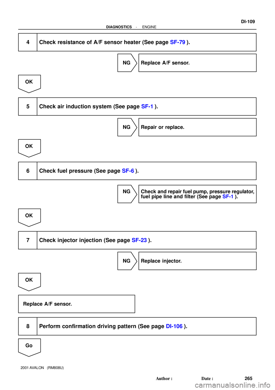
4 Check resistance of A/F sensor heater (See page SF-79).
NG Replace A/F sensor.
OK
5 Check air induction system (See page SF-1).
NG Repair or replace.
OK
6 Check fuel pressure (See page SF-6).
NG Check and repair fuel pump, pressure regulator,
fuel pipe line and filter (See page SF-1).
OK
7 Check injector injection (See page SF-23).
NG Replace injector.
OK
Replace A/F sensor.
8 Perform confirmation driving pattern (See page DI-106).
Go