Page 407 of 1897
BO41E-01
H17368
Outside Rear View Mirror
7.8 (80, 69 in.´lbf)
MirrorWire Retainer
Lower Frame
Bracket Garnish
Gasket
Door Trim Upper Armrest Base
Panel with Power
Window SwitchInside Handle Bezel
Courtesy Light
N´m (kgf´cm, ft´lbf) : Specified torqueTAIWAN:
Mirror
7.8 (80, 69 in.´lbf)
Outside Rear
View Mirror
- BODYOUTSIDE REAR VIEW MIRROR
BO-25
1810 Author�: Date�:
2001 AVALON (RM808U)
OUTSIDE REAR VIEW MIRROR
COMPONENTS
Page 409 of 1897

REMOVAL
1. REMOVE INSIDE HANDLE BEZEL
(a) Using a screwdriver, remove the cove")
BO41F-01
H04751
H12102
H12103
H12104Clip BO-26
- BODYOUTSIDE REAR VIEW MIRROR
1811 Author�: Date�:
2001 AVALON (RM808U)
REMOVAL
1. REMOVE INSIDE HANDLE BEZEL
(a) Using a screwdriver, remove the cover.
HINT:
Tape the screwdriver tip before use.
(b) Remove the screw.
(c) Using a screwdriver, remove the inside handle bezel as
shown in the illustration.
HINT:
Tape the screwdriver tip before use.
2. REMOVE COURTESY LIGHT
3. REMOVE UPPER ARMREST BASE PANEL WITH
POWER WINDOW SWITCH
(a) Using a screwdriver, remove the upper armrest base pan-
el with power window switch.
HINT:
Tape the screwdriver tip before use.
(b) Disconnect the connector.
4. REMOVE DOOR TRIM
(a) Using a screwdriver, remove the 2 caps.
HINT:
Tape the screwdriver tip before use.
(b) Remove the 6 screws and clip.
(c) Pull the trim upward to remove it.
5. REMOVE LOWER FRAME BRACKET GARNISH
Using a screwdriver, remove the lower frame bracket as shown
in the illustration.
HINT:
Tape the screwdriver tip before use.
6. REMOVE OUTSIDE REAR VIEW MIRROR
(a) Disconnect the connector.
(b) Remove the 3 nuts and outside rear view mirror.
Torque: 7.8 N´m (80 kgf´cm, 69 ft´lbf)
Page 412 of 1897
BO41E-01
H17368
Outside Rear View Mirror
7.8 (80, 69 in.´lbf)
MirrorWire Retainer
Lower Frame
Bracket Garnish
Gasket
Door Trim Upper Armrest Base
Panel with Power
Window SwitchInside Handle Bezel
Courtesy Light
N´m (kgf´cm, ft´lbf) : Specified torqueTAIWAN:
Mirror
7.8 (80, 69 in.´lbf)
Outside Rear
View Mirror
- BODYOUTSIDE REAR VIEW MIRROR
BO-25
1810 Author�: Date�:
2001 AVALON (RM808U)
OUTSIDE REAR VIEW MIRROR
COMPONENTS
Page 414 of 1897

REMOVAL
1. REMOVE INSIDE HANDLE BEZEL
(a) Using a screwdriver, remove the cove")
BO41F-01
H04751
H12102
H12103
H12104Clip BO-26
- BODYOUTSIDE REAR VIEW MIRROR
1811 Author�: Date�:
2001 AVALON (RM808U)
REMOVAL
1. REMOVE INSIDE HANDLE BEZEL
(a) Using a screwdriver, remove the cover.
HINT:
Tape the screwdriver tip before use.
(b) Remove the screw.
(c) Using a screwdriver, remove the inside handle bezel as
shown in the illustration.
HINT:
Tape the screwdriver tip before use.
2. REMOVE COURTESY LIGHT
3. REMOVE UPPER ARMREST BASE PANEL WITH
POWER WINDOW SWITCH
(a) Using a screwdriver, remove the upper armrest base pan-
el with power window switch.
HINT:
Tape the screwdriver tip before use.
(b) Disconnect the connector.
4. REMOVE DOOR TRIM
(a) Using a screwdriver, remove the 2 caps.
HINT:
Tape the screwdriver tip before use.
(b) Remove the 6 screws and clip.
(c) Pull the trim upward to remove it.
5. REMOVE LOWER FRAME BRACKET GARNISH
Using a screwdriver, remove the lower frame bracket as shown
in the illustration.
HINT:
Tape the screwdriver tip before use.
6. REMOVE OUTSIDE REAR VIEW MIRROR
(a) Disconnect the connector.
(b) Remove the 3 nuts and outside rear view mirror.
Torque: 7.8 N´m (80 kgf´cm, 69 ft´lbf)
Page 432 of 1897
BO2OS-01
H12120
Door Lock Striker
Rear Guide Bracket
Garnish
23 (230, 17)
Rear Door
Window Guide
Rear Door Weatherstrip
Rear Door Glass Run
Rear Door Glass
Outside Handle
5.4 (55, 48 in.´lbf)
5.4 (55, 48 in.´lbf)
�
Door Lock
Door Lock ProtectorRear Door Outside
Lower Moulding
Door Speaker Board
25 (260, 19)
25 (260, 19)25 (260, 19)
7.8 (80, 69 in.´lbf)
Door Check
25 (260, 19)
Door Hinge
Inside Handle
Inside Handle Bezel
Service Hole Cover
Rear Door Belt Moulding
Cover
Upper Armrest Base Panel
Power Window
Switch
Rear Door ArmrestRear Door
Inner Weatherstrip
Door Trimx13
x7
Window Regulator
Guide Assembly
Window Regulator Motor
5.4 (55, 48 in.´lbf)
Rear Door Trim Pocket
: Specified torqueN´m (kgf´cm, ft´lbf)
� Precoated Part
5.4 (55, 48 in.´lbf)
4.9 (50, 43 in.´lbf)
Guide Piece Plate
BO-16
- BODYREAR DOOR
1801 Author�: Date�:
2001 AVALON (RM808U)
REAR DOOR
COMPONENTS
Page 433 of 1897
BO2OT-01
H04751
H12111
H12113
Clip
H12114
- BODYREAR DOOR
BO-17
1802 Author�: Date�:
2001 AVALON (RM808U)
DISASSEMBLY
1. REMOVE INSIDE HANDLE BEZEL
(a) Using a screwdriver, remove the cover.
HINT:
Tape the screwdriver tip before use.
(b) Remove the screw.
(c) Using a screwdriver, remove the inside handle bezel as
shown in the illustration.
HINT:
Tape the screwdriver tip before use.
2. REMOVE UPPER ARMREST BASE PANEL WITH
POWER WINDOW SWITCH
(a) Using a screwdriver, remove the upper armrest base pan-
el with power window switch.
HINT:
Tape the screwdriver tip before use.
(b) Disconnect the connector.
(c) Remove the power window switch from the upper armrest
base panel.
3. REMOVE REAR GUIDE BRACKET GARNISH
Using a screwdriver, remove the rear guide bracket garnish.
HINT:
Tape the screwdriver tip before use.
4. REMOVE DOOR TRIM
(a) Remove the 3 screws and 2 clips.
(b) Pull the trim upward to remove it.
Page 824 of 1897
I13652
BatteryW-B
BM12
BB1
W-B
P151 22
5
Power WIndow
Motor RH
GP11
Power WIndow
Control Switch
Rear RH
D E
UB
DOWN
UP4
1
6L-W
R-BR-B R-B
G-B
G-BG-B 34
3 11 2 FL MAINB 1 1
F6 F10ALT W1G 1153
2
22
B5
B510RRD
RRU 12
1L PWR RELAY
P-B
6
IB2
P-B7
WLSWLG
D19
Driver
Door
ECU
1
1L RL P/W
10
1A BKJ11
J/C
A
W-B12
BA1
W-BP10
Power WIndow Control
Switch Rear LH
E
D
U R 212 P14
Power Window
Motor LHG
5DOWN
UP
B11
188
BA1
Y-R
Y-R
G-YG-Y
G-Y
PL-Y 4 6 3
3
2ID1
17
1B4
B422RLD
RLU
RBA1
ID1
BA1
IA1
RR P/W
FL Block
BB1
BB1
BB1IM2
IM2
IM2Body ECU
Driver Side J/BY-R
P
LG 3
- DIAGNOSTICSBODY CONTROL SYSTEM
DI-645
801 Author�: Date�:
2001 AVALON (RM808U)
Rear power window switch circuit
CIRCUIT DESCRIPTION
Power window switch circuit can be checked using DTC check. (Refer to DI-738)
WIRING DIAGRAM
DI6LS-01
Page 825 of 1897
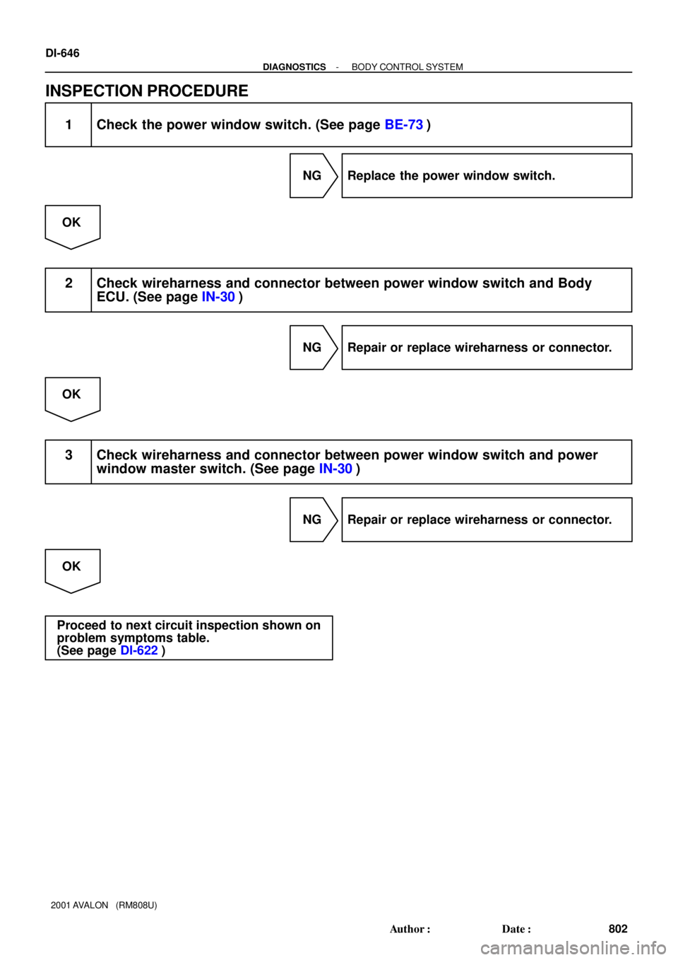
DI-646
- DIAGNOSTICSBODY CONTROL SYSTEM
802 Author�: Date�:
2001 AVALON (RM808U)
INSPECTION PROCEDURE
1 Check the power window switch. (See page BE-73)
NG Replace the power window switch.
OK
2 Check wireharness and connector between power window switch and Body
ECU. (See page IN-30)
NG Repair or replace wireharness or connector.
OK
3 Check wireharness and connector between power window switch and power
window master switch. (See page IN-30)
NG Repair or replace wireharness or connector.
OK
Proceed to next circuit inspection shown on
problem symptoms table.
(See page DI-622)

MirrorWire Retainer
Lower Frame
Bracket Garnish
Gasket
Door Trim Upper Armrest Base
Panel with Power
Window SwitchInside Handle Bezel")

MirrorWire Retainer
Lower Frame
Bracket Garnish
Gasket
Door Trim Upper Armrest Base
Panel with Power
Window SwitchInside Handle Bezel")

Rear Door
Window Guide
Rear Door Weatherstrip
Rear Door Glass Run
Rear Door Glass
Outside Handle
5.4 (55, 48 in.´lbf)
5.4 (55")