Page 993 of 1897
DI-1 14
- DIAGNOSTICSENGINE
270 Author�: Date�:
2001 AVALON (RM808U)
10 Did vehicle runs out of fuel in past?
NO Check for intermittent problems
(See page DI-3).
YES
DTC P1133 or P1153 is caused by running out
of fuel.
Page 994 of 1897

(-)
- DIAGNOSTICSENGINE
DI-1 15
271 Author�: Date�:
2001 AVALON (RM808U)
DTC P1135 A/F Sensor Heater Circuit Malfunction (Bank
1 Sensor 1)
DTC P1155 A/F Sensor Heater Circuit")
A02032
HAFL ON
HAFR
(+)
(-)
- DIAGNOSTICSENGINE
DI-1 15
271 Author�: Date�:
2001 AVALON (RM808U)
DTC P1135 A/F Sensor Heater Circuit Malfunction (Bank
1 Sensor 1)
DTC P1155 A/F Sensor Heater Circuit Malfunction (Bank
2 Sensor 1)
CIRCUIT DESCRIPTION
Refer to DTC P0125 on page DI-43.
DTC No.DTC Detecting ConditionTrouble Area
P1135
When the heater operates, heater current exceeds 8 A
(2 trip detection logic)�Open or short in heater circuit of A/F sensor
A/F h tP1135
P1155Heater current of 0.25 A or less when the heater operates
(2 trip detection logic)�A/F sensor heater
�ECM
WIRING DIAGRAM
Refer to DTC P0125 on page DI-43.
INSPECTION PROCEDURE
HINT:
Read freeze frame data using TOYOTA hand-held tester or OBD II scan tool. Because freeze frame records
the engine conditions when the malfunction is detected. When troubleshooting, it is useful for determining
whether the vehicle was running or stopped, the engine was warmed up or not, the air-fuel ratio was lean
or rich, etc. at the time of the malfunction.
1 Check voltage between terminals HAFL, HAFR of ECM connector and body
ground.
PREPARATION:
(a) Remove the glove compartment (See page SF-83).
(b) Turn the ignition switch ON.
CHECK:
Measure the voltage between terminals HAFL, HAFR of the
ECM connector and body ground.
OK:
Voltage: 9 - 14 V
OK Check and replace ECM (See page IN-30).
NG
2 Check resistance of A/F sensor heater (See page SF-79).
DI2H9-03
Page 995 of 1897
DI-1 16
- DIAGNOSTICSENGINE
272 Author�: Date�:
2001 AVALON (RM808U)
NG Replace A/F sensor.
OK
3 Check A/F sensor heater relay (Marking: A/F) (See page SF-61).
NG Replace A/F sensor heater relay.
OK
Check and repair harness or connector between A/F sensor heater relay and A/F sensor, and A/F
sensor and ECM (See page IN-30).
Page 997 of 1897

A11669
14
3 2
B-R
L LG-B
L-Y
LG 1
4
2
43
21
43
21
43
21
43
2
Ignition Coil
with Igniter
No.2
No.3
No.4
No.5
No.6
Noise
Filter B-Y W-BB-W
GR
13 No.1B-W
B-W B-W B-W
B-WB-Y
B-Y B-Y B-Y B-Y B-Y
W-B
W-B
W-B
W-B W-B
1
B-W
B-WW-B
B-W
B-W
B-WW-B W-B W-B
B-W
W-BIGT1
IGF IGT2
IGT3
IGT4
IGT5
IGT6 11
12
13
14
15
16
25 E4
E4
E4
E4
E4
E4
E4ECM
Battery
EC ED
115
2B
B-O
2F 1C28
3
IG Switch72
14 IG2 Reray
2G
2C 2CIG2
AM2 72
1J B-O
7
6W-R
W-R4
IF1Engine Room J/B
Driver Side J/BB
Fusible
Link
Block
FL
Main 1F6 F7
B-W
1 B-Y
B-Y B-Y B-Y
W-B
DI-1 18
- DIAGNOSTICSENGINE
274 Author�: Date�:
2001 AVALON (RM808U)
WIRING DIAGRAM
INSPECTION PROCEDURE
HINT:
�If DTC P1300 is displayed, check No.1 ignition coil with igniter circuit.
�If DTC P1305 is displayed, check No.2 ignition coil with igniter circuit.
�If DTC P1310 is displayed, check No.3 ignition coil with igniter circuit.
�If DTC P1315 is displayed, check No.4 ignition coil with igniter circuit.
�If DTC P1320 is displayed, check No.5 ignition coil with igniter circuit.
�If DTC P1325 is displayed, check No.6 ignition coil with igniter circuit.
�If DTCs P1300, P1315 and P1325, are output simultaneously, IGF1 circuit may be open or short.
�If DTCs P1305, P1310 and P1320, are output simultaneously, IGF2 circuit may be open or short.
�Read freeze frame data using TOYOTA hand-held tester or OBD II scan tool. Because freeze frame
records the engine conditions when the malfunction is detected. When troubleshooting, it is useful for
determining whether the vehicle was running or stopped, the engine was warmed up or not, the air-fuel
ratio was lean or rich, etc. at the time of the malfunction.
1 Check spark plug and spark (See page DI-58).
Page 998 of 1897
A02033
ON
IGF
(+) (-)
- DIAGNOSTICSENGINE
DI-1 19
275 Author�: Date�:
2001 AVALON (RM808U)
NG Go to step 4.
OK
2 Check for open and short in harness and connector in IGF and IGT signal cir-
cuits between ECM and ignition coil with igniter (See page IN-30).
NG Repair or replace harness or connector.
OK
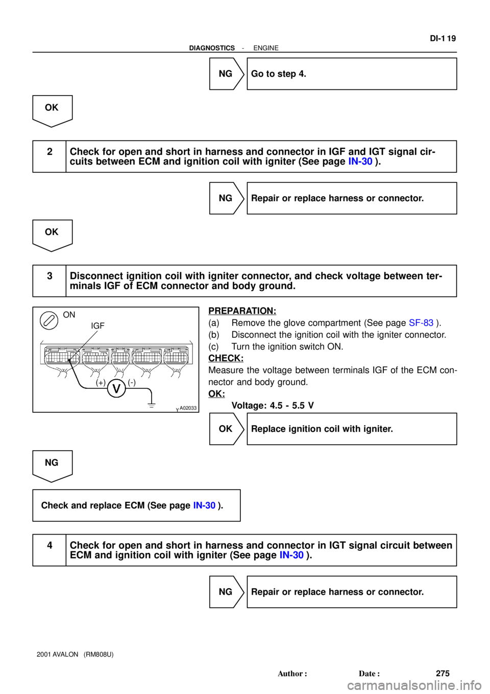
3 Disconnect ignition coil with igniter connector, and check voltage between ter-
minals IGF of ECM connector and body ground.
PREPARATION:
(a) Remove the glove compartment (See page SF-83).
(b) Disconnect the ignition coil with the igniter connector.
(c) Turn the ignition switch ON.
CHECK:
Measure the voltage between terminals IGF of the ECM con-
nector and body ground.
OK:
Voltage: 4.5 - 5.5 V
OK Replace ignition coil with igniter.
NG
Check and replace ECM (See page IN-30).
4 Check for open and short in harness and connector in IGT signal circuit between
ECM and ignition coil with igniter (See page IN-30).
NG Repair or replace harness or connector.
Page 999 of 1897
 (-)
A06097
IGT Signal Waveform5 V/
Division
IGT
GND
IGFGND
20 msec./ Division
A07629
ON
IGT1
IGT6IGT5IGT4
IGT2 IGT3
(+) (-)
DI-120
- DIAGNOSTICSENGINE
276 Aut")
A07629
ON
IGT1
IGT6IGT5IGT4
IGT2 IGT3
(+) (-)
A06097
IGT Signal Waveform5 V/
Division
IGT
GND
IGFGND
20 msec./ Division
A07629
ON
IGT1
IGT6IGT5IGT4
IGT2 IGT3
(+) (-)
DI-120
- DIAGNOSTICSENGINE
276 Author�: Date�:
2001 AVALON (RM808U)
OK
5 Check voltage between terminals IGT1 - IGT6 of ECM connector and body
ground.
PREPARATION:
(a) Remove the glove compartment (See page SF-83).
(b) Turn the ignition switch ON.
CHECK:
Measure the voltage between terminals IGT1 - IGT6 of the
ECM connector and body ground when the engine is cranked.
OK:
Voltage: More than 0.1 V and less than 4.5 V
Reference: INSPECTION USING OSCILLOSCOPE
During cranking or idling, check the waveform between termi-
nals IGT1 - IGT6 and E1 of the ECM connector.
HINT:
Correct waveform appears as shown, with rectangle waves.
NG Check and replace ECM (See page IN-30).
OK
6 Disconnect ignition coil with igniter connector, and check voltage between ter-
minals IGT1 - IGT6 of ECM connector and body ground.
PREPARATION:
(a) Remove the glove compartment (See page SF-83).
(b) Disconnect the ignition coil with the igniter connector.
(c) Turn the ignition switch ON.
CHECK:
Measure the voltage between terminals IGT1 - IGT6 of the
ECM connector and body ground when the engine is cranked.
OK:
Voltage: More than 0.1 V and less than 4.5 V
NG Check and replace ECM (See page IN-30).
OK
Page 1000 of 1897
BE6653A01761A01861
ON
START1
(+)
(-)
A11423
Engine Room J/B
IG2
Fuse
- DIAGNOSTICSENGINE
DI-121
277 Author�: Date�:
2001 AVALON (RM808U)
7 Check ignition coil with igniter power source circuit.
PREPARATION:
Disconnect the ignition coil with the igniter connector.
CHECK:
Measure the voltage between terminal 1 of the ignition coil with
the igniter connector and body ground when the ignition switch
is turned to ON and START position.
OK:
Voltage: 9 - 14 V
NG Repair ignition coil with igniter power source
circuit.
OK
8 Check for open and short in harness and connector between ignition switch and
ignition coil with igniter (See page IN-30).
NG Repair or replace harness or connector.
OK
9 Check IG2 fuse.
PREPARATION:
Remove the IG2 fuse from the engine room J/B.
CHECK:
Check the continuity of the IG2 fuse.
OK:
Continuity
NG Check for short in all harness and components
connected to IG2 fuse.
OK
Page 1001 of 1897
A11423
Engine Room J/B
AM2
Fuse
DI-122
- DIAGNOSTICSENGINE
278 Author�: Date�:
2001 AVALON (RM808U)
10 Check AM2 fuse.
PREPARATION:
Remove the AM2 fuse from the engine room J/B.
CHECK:
Check the continuity of the AM2 fuse.
OK:
Continuity
NG Check for short in all harness and components
connected to AM2 fuse.
OK
11 Check ignition relay (Marking: IG2) (See page IG-10).
NG Replace ignition relay.
OK
Replace ignition coil with igniter.