Page 526 of 1897

INSPECTION
1. INSPECT DISASSEMBLED PARTS
Inspect the disassembled part")
BR0LI-03
R00311
F06409
BR0828
R00343
Shim
Clearance
R00313
- BRAKEPARKING BRAKE
BR-45
1444 Author�: Date�:
2001 AVALON (RM808U)
INSPECTION
1. INSPECT DISASSEMBLED PARTS
Inspect the disassembled parts for wear, rust or damage.
2. MEASURE BRAKE SHOE LINING THICKNESS
Using a ruler, measure the thickness of the shoe lining.
Standard thickness: 2.0 mm (0.079 in.)
Minimum thickness: 1.0 mm (0.039 in.)
If the lining thickness is at the minimum thickness or less, or if
there is severe, uneven wear, replace the brake shoe.
3. MEASURE DISC INSIDE DIAMETER
Using a brake drum gauge or equivalent, measure the inside di-
ameter of the disc.
Standard inside diameter: 170 mm (6.69 in.)
Maximum inside diameter: 171 mm (6.73 in.)
Replace the disc if the inside diameter is at the maximum value
or more. Replace the disc or grind it with a lathe if the disc is
scored or worn unevenly.
4. INSPECT PARKING BRAKE LINING AND DISC FOR
PROPER CONTACT
Apply chalk to the inside surface of the disc, then grind down
the brake shoe lining to fit. If the contact between the disc and
the brake shoe lining is improper, repair it using a brake shoe
grinder or replace the brake shoe assembly.
5. MEASURE CLEARANCE BETWEEN PARKING
BRAKE SHOE AND LEVER
Using a feeler gauge, measure the clearance.
Standard clearance: Less than 0.35 mm (0.0138 in.)
If the clearance is not within the specification, replace the shim
with one of the correct size.
Shim ThicknessShim Thickness
0.3 mm (0.012 in.)0.9 mm (0.035 in.)
0.6 mm (0.024 in.)-
6. IF NECESSARY, REPLACE SHIM
(a) Using a screwdriver, remove the C-washer and shim.
(b) Install the correct size shim with a new C-washer.
(c) Remeasure the clearance.
Page 527 of 1897
BR0LJ-03
BR0823
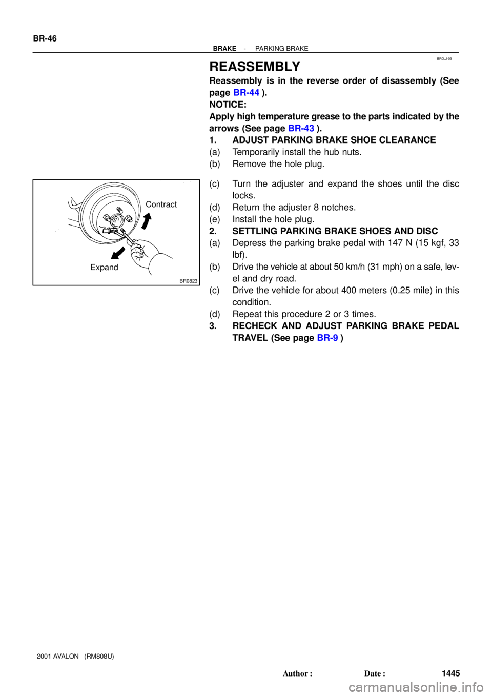
Contract
Expand BR-46
- BRAKEPARKING BRAKE
1445 Author�: Date�:
2001 AVALON (RM808U)
REASSEMBLY
Reassembly is in the reverse order of disassembly (See
page BR-44).
NOTICE:
Apply high temperature grease to the parts indicated by the
arrows (See page BR-43).
1. ADJUST PARKING BRAKE SHOE CLEARANCE
(a) Temporarily install the hub nuts.
(b) Remove the hole plug.
(c) Turn the adjuster and expand the shoes until the disc
locks.
(d) Return the adjuster 8 notches.
(e) Install the hole plug.
2. SETTLING PARKING BRAKE SHOES AND DISC
(a) Depress the parking brake pedal with 147 N (15 kgf, 33
lbf).
(b) Drive the vehicle at about 50 km/h (31 mph) on a safe, lev-
el and dry road.
(c) Drive the vehicle for about 400 meters (0.25 mile) in this
condition.
(d) Repeat this procedure 2 or 3 times.
3. RECHECK AND ADJUST PARKING BRAKE PEDAL
TRAVEL (See page BR-9)
Page 528 of 1897
BR0KK-03
F09711N´m (kgf´cm, ft´lbf) : Specified torqueLower LH Panel Insert
Lower No. 1 Instrument Panel
Pedal Pad
No. 2 Heater to Register Duct
Clip
Parking Brake Cable
Parking Brake Pedal Assembly
61 (620, 45)
61 (620, 45)
Cushion
Parking Brake Switch
61 (620, 45)
BR-10
- BRAKEPARKING BRAKE PEDAL
1409 Author�: Date�:
2001 AVALON (RM808U)
COMPONENTS
Page 529 of 1897
BR0KM-03
BR-12
- BRAKEPARKING BRAKE PEDAL
1411 Author�: Date�:
2001 AVALON (RM808U)
INSTALLATION
Installation is in the reverse order of removal (See page BR-1 1).
AFTER INSTALLATION, ADJUST PARKING BRAKE PEDAL TRAVEL (See page BR-6)
Page 530 of 1897

PARKING BRAKE PEDAL
ON-VEHICLE INSPECTION
1. C")
R00254
BR0KJ-02
F09710No. 4 CableLock Nut
Adjusting Hexagon
W03176
Red Paint
- BRAKEPARKING BRAKE PEDAL
BR-9
1408 Author�: Date�:
2001 AVALON (RM808U)
PARKING BRAKE PEDAL
ON-VEHICLE INSPECTION
1. CHECK PARKING BRAKE PEDAL TRAVEL
Slowly depress the parking brake pedal all the way, and count
the number of clicks.
Parking brake pedal travel at 294 N (30 kgf, 66 lbf):
3 - 6 clicks
If incorrect, adjust the parking brake.
2. IF NECESSARY, ADJUST PARKING BRAKE PEDAL
TRAVEL
HINT:
Before adjusting the parking brake, make sure that the rear
brake shoe clearance has been adjusted.
For shoe clearance adjustment, see step 1 on page BR-46.
(a) Floor shift:
Remove the console box.
(b) Column shift:
Remove the hole cover.
(c) Confirm that the parking brake pedal is released.
(d) Hold the screw end of No. 4 cable not to rotate.
(e) Loosen the lock nut.
(f) Hold the parking brake cable and turn the adjusting hexa-
gon until the pedal travel is correct.
NOTICE:
To prevent the parking brake cable from twisting, always
keep the red-painted surface up.
(g) Holding the adjusting hexagon, tighten the lock nut.
Torque: 5.4 N´m (55 kgf´cm, 48 in.´lbf)
(h) Floor shift:
Install the console box.
(i) Column shift:
Install the hole cover.
Page 531 of 1897
BR151-01
F09746
F09747
- BRAKEPARKING BRAKE PEDAL
BR-1 1
1410 Author�: Date�:
2001 AVALON (RM808U)
REMOVAL
1. REMOVE LOWER NO. 1 INSTRUMENT PANEL, LOW-
ER LH PANEL INSERT AND NO. 2 HEATER TO REG-
ISTER DUCT (See page BO-87)
2. RELEASE PARKING BRAKE PEDAL
3. REMOVE PARKING BRAKE PEDAL ASSEMBLY
(a) Disconnect the parking brake switch connector.
(b) Remove the clip, and disconnect the parking brake cable.
(c) Remove the 3 nuts and parking brake pedal assembly.
Torque: 61 N´m (620 kgf´cm, 45 ft´lbf)
(d) Remove the parking brake switch and cushion from the
parking brake pedal assembly.
Page 547 of 1897

TROUBLESHOOTING
PROBLEM SYMPTOMS TABLE
Use the table below to help you find the cause of the problem. The numbers indic")
BR0KG-05
BR-2
- BRAKETROUBLESHOOTING
1401 Author�: Date�:
2001 AVALON (RM808U)
TROUBLESHOOTING
PROBLEM SYMPTOMS TABLE
Use the table below to help you find the cause of the problem. The numbers indicate the priority of the likely
cause of the problem. Check each part in order. If necessary, replace these parts.
SymptomSuspect AreaSee page
Lower pedal or spongy pedal
5. Fluid leaks for brake system
6. Air in brake system
7. Piston seals (Worn or damaged)
8. Master cylinder (Faulty)
9. Booster push rod (Out of adjustment)DI-249
DI-346
BR-4
BR-28
BR-37
BR-13
BR-24
Brake drag
1. Brake pedal freeplay (Minimal)
2. Parking brake pedal travel (Out of adjustment)
3. Parking brake wire (Sticking)
4. Rear brake shoe clearance (Out of adjustment)
5. Pad (Cracked or distorted)
6. Piston (Stuck)
7. Piston (Frozen)
8. Tension or return spring (Faulty)
9. Booster push rod (Out of adjustment)
10.Vacuum leaks for booster system
11. Master cylinder (Faulty)BR-6
BR-9
-
BR-46
BR-25
BR-34
BR-28
BR-37
BR-28
BR-37
BR-43
BR-24
BR-22
BR-13
Brake pull
1. Piston (Stuck)
2. Pad (Oily)
3. Piston (Frozen)
4. Disc (Scored)
5. Pad (Cracked or distorted)BR-28
BR-37
BR-25
BR-34
BR-28
BR-37
BR-28
BR-37
BR-25
BR-34
Hard pedal but brake inefficient
1. Fluid leaks for brake system
2. Air in brake system
3. Piston (Stuck)
4. Pad (Cracked or distorted)
5. Pad (Oily)
6. Pad (Glazed)
7. Disc (Scored)
8. Booster push rod (Out of adjustment)
9. Vacuum leaks for booster systemDI-249
DI-346
BR-4
BR-28
BR-37
BR-25
BR-34
BR-25
BR-34
BR-25
BR-34
BR-28
BR-37
BR-24
BR-22
Page 602 of 1897
F09801
ABS Actuator
and ECU
A713
Battery J/B No. 3A21
Active Light Relay
Multi DisplayY-B
BRAKEPKB
PKB
Ignition Switch
IF1 A721
EBDW IE15
Y-B
6 5
8 3 Y-G
3B14
3A
6 3B
5
Y-G
B4
15R-W
IE116
R-Y
Y-G
1
P3
Parking
Brake
Switch W-BBody ECU
J1
J/CDriver Side J/B
B1
Bake Fluid
Level Warning
Switch
J/B No. 3
R-W3H
153B
15
15
3A
12
1I8
1H
R-W
1
2
B B
Engine Room J/BDriver Side J/BGAUGE No. 1 IG1 Relay
4
2D4
2F
W-B
ED
R-WR-WIC17
M63
M64R-B
J/B No. 4
13
4F4
4D
R-B
10
1D 1
2
3 44
1C 3
1B1
1G W
IGW-BEngine Room J/BEngine Room R/B No. 57
BAM1
B-L
FL Block
ALT5 512 1
2H 1
2G
1
F8
F10F61
BFL MAIN W-B
142
W-R
W-L
W-L R-Y DI-240
- DIAGNOSTICSANTI-LOCK BRAKE SYSTEM WITH ELECTRONIC
BRAKE FORCE DISTRIBUTION (EBD)
396 Author�: Date�:
2001 AVALON (RM808U)
BRAKE Warning Light Circuit
CIRCUIT DESCRIPTION
The BRAKE warning light lights up when the brake fluid is insufficient, parking brake is applied or the EBD
is defective.
WIRING DIAGRAM
DI6NL-02
 : Specified torqueLower LH Panel Insert
Lower No. 1 Instrument Panel
Pedal Pad
No. 2 Heater to Register Duct
Clip
Parking Brake Cable
Parking Brake Pedal Assembl")