Page 603 of 1897
- DIAGNOSTICSANTI-LOCK BRAKE SYSTEM WITH ELECTRONIC
BRAKE FORCE DISTRIBUTION (EBD)DI-241
397 Author�: Date�:
2001 AVALON (RM808U)
INSPECTION PROCEDURE
1 Check parking brake switch circuit (See page BE-53).
NG Repair or replace parking brake switch circuit.
OK
2 Check brake fluid level warning switch circuit (See page BE-53).
NG Repair or replace brake fluid level warning
switch circuit.
OK
3 Is DTC output for ABS ?
Yes Repair circuit indicated by the output code.
No
4 Check BRAKE warning light.
See combination meter troubleshooting on page BE-2.
NG Repair or replace combination meter.
OK
Page 633 of 1897

DI6N7-01
F07879
F02201
E1Tc
DLC1
F00103
Normal Code
0.25 sec.
0.25 sec. 0.5 sec.
ON
OFF
ON
OFF0.5 sec. 0.5 sec.
Code 11 and 21
4 sec.1.5 sec.
2.5 sec.
Code 11 Code 21
DI-212- DIAGNOSTICSANTI-LOCK BRAKE SYSTEM WITH ELECTRONIC
BRAKE FORCE DISTRIBUTION (EBD)
368 Author�: Date�:
2001 AVALON (RM808U)
PRE-CHECK
1. DIAGNOSIS SYSTEM
(a) Release the parking brake pedal.
(b) Check the indicator.
When the ignition switch is turned ON, check that the ABS
warning light and BRAKE warning light goes on for
approx. 3 seconds.
HINT:
�When the parking brake is applied or the level of the brake
fluid is low, the BRAKE warning light is lit.
�If the indicator check result is not normal, proceed to trou-
bleshooting for the ABS warning light circuit or BRAKE
warning light circuit (See page DI-243, DI-240).
(c) Check the DTC.
(1) Using SST, connect terminals Tc and E
1 of DLC1.
SST 09843-18020
(2) Turn the ignition switch ON and read the DTC from
the ABS warning light on the combination meter.
HINT:
�If no codes appears, inspect the diagnostic circuit or ABS
warning light circuit (See page DI-245 or DI-243).
�As an example, the blinking patterns for normal code and
codes 11 and 21 are shown on the left.
(3) Codes are explained in the code table on page
DI-215.
(4) After completing the check, disconnect terminals Tc
and E
1, and turn off the display.
If 2 or more malfunction codes are identified at the
same time, the lowest numbered DTC will be dis-
played 1st.
Page 646 of 1897

F09824
Battery
FL MAIN F10 F8
F611 1
ALT
BFL BlockB-L 2G 2H1 1 Engine Room J/B B5512 AM1 Engine Room R/B No. 5 W-LIF17
W-L
2
IG1 AM1 4Ignition Switch W-R W
1C 1G
1B 1D
4
4 3 1
1
2
3 10 GAUGE No. 1 Driver Side J/B
IG1 Relay
W-B
IG
ED CUP
BRAKE
Multi DisplayM6 M3M6R-B
3 4
74D 4F13
4 J/B No. 4
R-B
L-O L-O6
IL1
R-WR-W
R-W
R-W
7
IC13A21
Active
Light
RelayR-Y 8A20
6040 74 68
32 ABS & BA &
TRAC & VSC ECU
FSS LBL PKB EBDW SP1
T5
T5
T5
T5 T5
Y-G
L-B
BR (Shielded)15
25 16
2
11
LBL LVL2PKB2BRL
PKB
Y-G Y-G
R-W
R-WJ/B No. 3
3B 3A
3A 3B 5
15
15 14
1Driver Side J/B
B1
Brake Fluid Level
Warning Switch Translate ECU
1H
1I 12
8
R-W
1 2
W-B J1 J/C
B B
W-BEngine Room J/B
44
2D2FW-B P3
Parking
Brake
SwitchA20
A20
A20
A20 DI-330
- DIAGNOSTICSABS WITH EBD & BA & TRAC & VSC SYSTEM
486 Author�: Date�:
2001 AVALON (RM808U)
BRAKE Warning Light Circuit
CIRCUIT DESCRIPTION
�The BRAKE warning light lights up when the brake fluid is insufficient, when the parking brake is ap-
plied or when the EBD is defective.
�If the translate ECU detects trouble, it makes VSC warning light lights up while prohibiting VSC & TRAC
control. At this time, the ECU records a DTC in memory. Connect terminals Tc and E
1 of the DLC1 or
DLC2 to make BRAKE warning light blink and output the DTC.
WIRING DIAGRAM
DI6OK-02
Page 647 of 1897
- DIAGNOSTICSABS WITH EBD & BA & TRAC & VSC SYSTEM
DI-331
487 Author�: Date�:
2001 AVALON (RM808U)
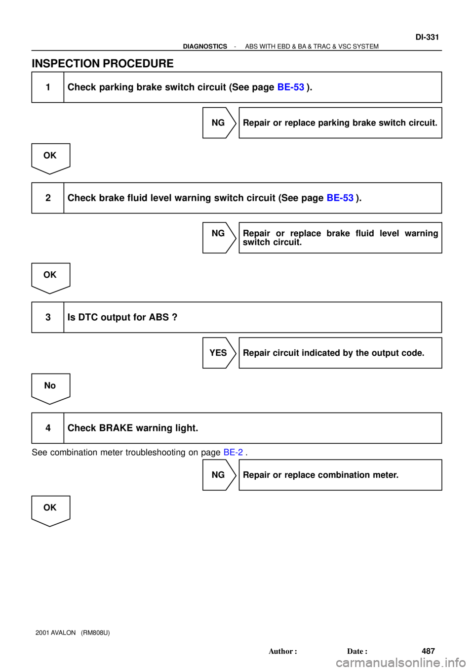
INSPECTION PROCEDURE
1 Check parking brake switch circuit (See page BE-53).
NG Repair or replace parking brake switch circuit.
OK
2 Check brake fluid level warning switch circuit (See page BE-53).
NG Repair or replace brake fluid level warning
switch circuit.
OK
3 Is DTC output for ABS ?
YES Repair circuit indicated by the output code.
No
4 Check BRAKE warning light.
See combination meter troubleshooting on page BE-2.
NG Repair or replace combination meter.
OK
Page 672 of 1897

F09814
J/B No. 3
15
3B 15
3AABS & BA & TRAC
& VSC ECU
40
A20
LBL Driver Side J/B
Engine Room J/B
M6
Multi
DisplayIC1 Translate
ECU
L-B 25
T5 11
T5
16
T5R-W
7
R-W
3
4
R-B LVL2LBL
BRL R-W
R-W
Level
Warning Switch12
1I 8
1H
R-W
12
BB J1
J/B
W-B
EDDriver Side J/B
GAUGE No. 1
W-B
W-B
J/B No. 4
10
1DR-B4
4D13
4F 4
2D4
2F
BRAKE
DI-290
- DIAGNOSTICSABS WITH EBD & BA & TRAC & VSC SYSTEM
446 Author�: Date�:
2001 AVALON (RM808U)
DTC C1202 / 44 Brake Fluid Level Warning Switch Cir-
cuit
CIRCUIT DESCRIPTION
The brake fluid level warning switch sends appropriate signals to the ECU when the brake fluid level is low-
ered.
HINT:
Depressing the parking brake pedal turns on the brake warning light, but this DTC No. C1202/44 is not out-
put.
DTC No.DTC Detecting ConditionTrouble Area
C1202 / 44
Fluid level in the brake master cylinder reservoir tank re-
mains low for 60 sec. or more. This means brake fluid
warning switch likes on.�Brake fluid level
�Brake fluid level warning switch
�Brake fluid level warning switch circuit
WIRING DIAGRAM
DI6O3-01
Page 721 of 1897

DTC chart of translate ECU(output NG code DTC of VSC system C1301/42 only):
DTC No.
(See Page)Detec")
DI-260
- DIAGNOSTICSABS WITH EBD & BA & TRAC & VSC SYSTEM
416 Author�: Date�:
2001 AVALON (RM808U)
DTC chart of translate ECU(output NG code DTC of VSC system C1301/42 only):
DTC No.
(See Page)Detection ItemTrouble Area
Normal code*
(DI-317)Malfunction in ECM control system
�ECM circuit
�ECM
�Brake fluid level
�Brake fluid level warning switch circuit
�Steering angle sensor
�ABS & BA & TRAC & VSC ECU
42
(DI-31 1)Malfunction in communication with the ABS & BA & TRAC &
VSC ECU�VSC+ or VSC- circuit
�Translate ECU
�ABS & BA & TRAC & VSC ECU
44
(DI-313)Open or short circuit in NEO circuit
�NEO circuit
�ECM
�Translate ECU
53
(DI-315)Malfunction in communication with the ECM
�TRC+ or TRC- circuit
�ENG+ or ENG- circuit
�ECM
�Translate ECU
Non code
(DI-318)Malfunction in translate ECU
�Tc terminal circuit
�BRAKE warning light circuit
�Translate ECU
*: Translate ECU is normal.
HINT:
The BRAKE warning light does not turn on due to an error in VSC.
If it is on, check that the parking brake pedal is released, the brake fluid level is normal and no malfunction
is identified in the fluid level warning switch system.
Page 723 of 1897
DI6NU-01
F07883
ABS Warning Light
VSC Warning Light
VSC OFF Indicator Light
SLIP Indicator Light
BRAKE Warning Light
DLC2Rear Speed Sensor
Sensor Rotor
Brake Actuator
ABS & BA & TRAC & VSC ECU
VSC OFF Switch Front Speed Sensor
DLC1
ABS Solenoid RelayABS Motor Relay
Room R/B No. 8 Engine
Precharge PumpMaster Cylinder
Pressure Sensor
Parking Brake Switch
Stop Light Switch
Translate ECU
Front Speed Sensor
Sensor Rotor
Sensor Rotor
Rear Speed Sensor
DLC3
Steering Angle Sensor
Yaw Rate Sensor
(Including Deceleration Sensor)
Active Lamp Relay
- DIAGNOSTICSABS WITH EBD & BA & TRAC & VSC SYSTEM
DI-261
417 Author�: Date�:
2001 AVALON (RM808U)
PARTS LOCATION
Page 724 of 1897

PRE-CHECK
1. DIAGNOSIS SYSTEM
(a) Check the warning lights.
(1) Re")
F07880
DI6NS-01
F02201Tc E
1DLC1
DI-252
- DIAGNOSTICSABS WITH EBD & BA & TRAC & VSC SYSTEM
408 Author�: Date�:
2001 AVALON (RM808U)
PRE-CHECK
1. DIAGNOSIS SYSTEM
(a) Check the warning lights.
(1) Release the parking brake pedal.
(2) When the ignition switch is turned ON, check that
the ABS warning light, VSC warning light, VSC OFF
indicator light, BRAKE warning light and SLIP indi-
cator light goes on for approx. 3 seconds.
HINT:
�When the parking brake is applied or the level of the brake
fluid is low, the BRAKE warning light is lit.
�If the indicator check result is not normal, proceed to trou-
bleshooting for the ABS warning light circuit, VSC warn-
ing light circuit, VSC OFF indicator light circuit, BRAKE
warning light circuit or SLIP indicator light circuit.
Trouble AreaSee page
ABS warning light circuitDI-325
VSC warning light circuitDI-327
VSC OFF indicator light circuitDI-336
BRAKE warning light circuitDI-330
SLIP indicator light circuitDI-333
(b) In case of not using TOYOTA hand-held tester:
Check the DTC of ABS & BA & TRAC & VSC ECU.
(1) Using SST, connect terminals Tc and E
1 of DLC1.
SST 09843-18020
(2) Turn the ignition switch ON.
(3) Read the DTC from the ABS warning light and VSC
warning light on the combination meter.
HINT:
�If no code appears, inspect the diagnostic circuit, ABS
warning light circuit or VSC waning light circuit.
Trouble AreaSee page
Tc terminal circuitDI-342
ABS warning light circuitDI-325
VSC warning light circuitDI-327