Page 1621 of 1897

B09079
B09076
Fuel Hose
Clamp
S04508
Ohmmeter
4
5
S04509
4
5
Battery SF-8
- SFIFUEL PUMP
111 7 Author�: Date�:
2001 AVALON (RM808U)
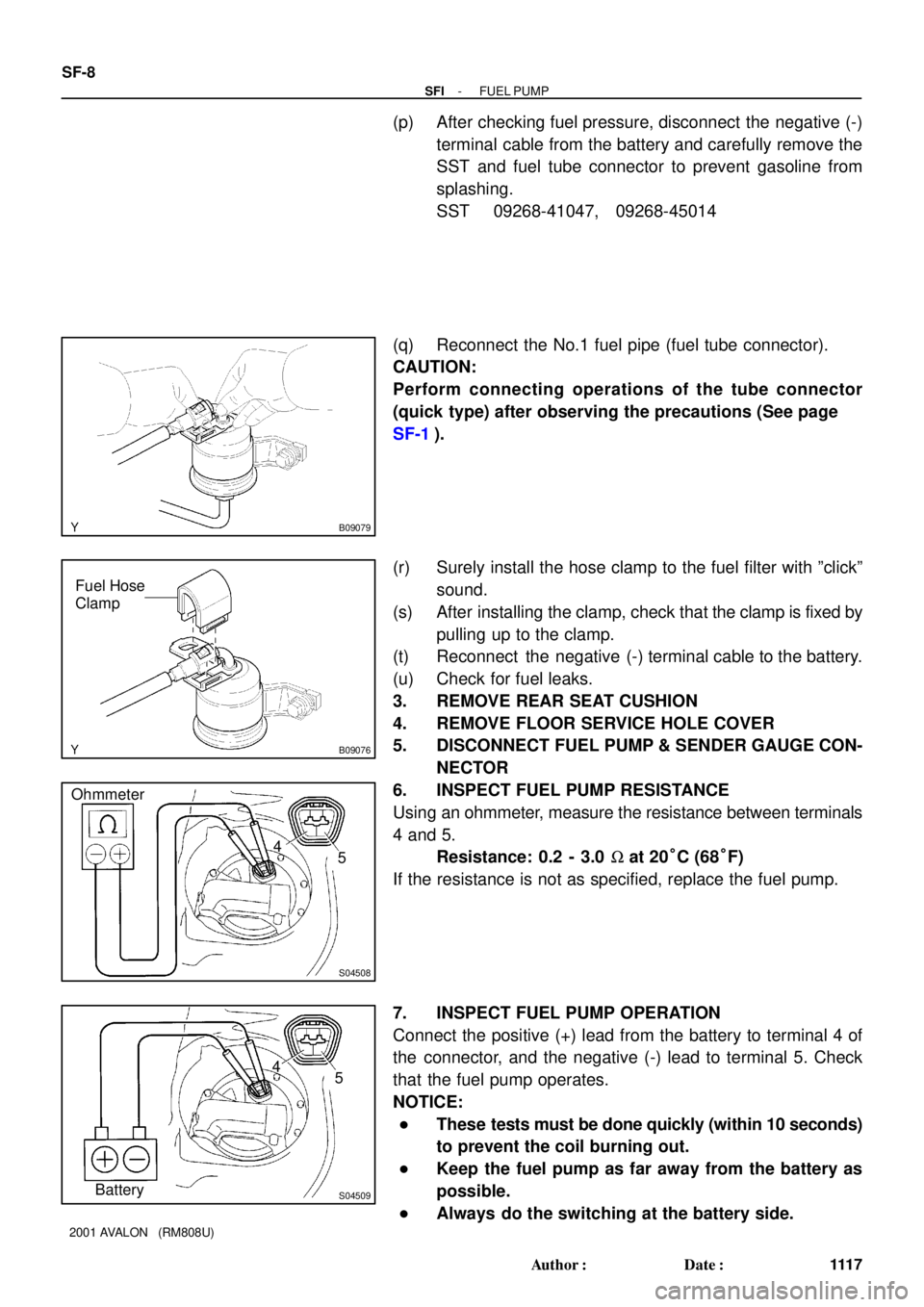
(p) After checking fuel pressure, disconnect the negative (-)
terminal cable from the battery and carefully remove the
SST and fuel tube connector to prevent gasoline from
splashing.
SST 09268-41047, 09268-45014
(q) Reconnect the No.1 fuel pipe (fuel tube connector).
CAUTION:
Perform connecting operations of the tube connector
(quick type) after observing the precautions (See page
SF-1).
(r) Surely install the hose clamp to the fuel filter with ºclickº
sound.
(s) After installing the clamp, check that the clamp is fixed by
pulling up to the clamp.
(t) Reconnect the negative (-) terminal cable to the battery.
(u) Check for fuel leaks.
3. REMOVE REAR SEAT CUSHION
4. REMOVE FLOOR SERVICE HOLE COVER
5. DISCONNECT FUEL PUMP & SENDER GAUGE CON-
NECTOR
6. INSPECT FUEL PUMP RESISTANCE
Using an ohmmeter, measure the resistance between terminals
4 and 5.
Resistance: 0.2 - 3.0 W at 20°C (68°F)
If the resistance is not as specified, replace the fuel pump.
7. INSPECT FUEL PUMP OPERATION
Connect the positive (+) lead from the battery to terminal 4 of
the connector, and the negative (-) lead to terminal 5. Check
that the fuel pump operates.
NOTICE:
�These tests must be done quickly (within 10 seconds)
to prevent the coil burning out.
�Keep the fuel pump as far away from the battery as
possible.
�Always do the switching at the battery side.
Page 1624 of 1897

SF0LF-01
S04583
B02519
Vinyl Bag
- SFIFUEL PUMP
SF-1 1
1120 Author�: Date�:
2001 AVALON (RM808U)
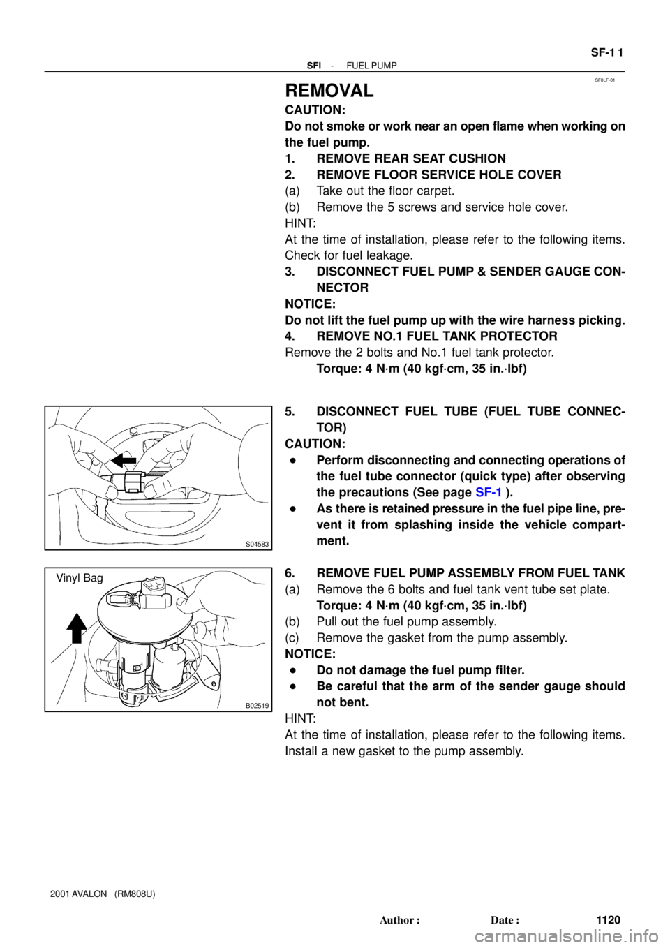
REMOVAL
CAUTION:
Do not smoke or work near an open flame when working on
the fuel pump.
1. REMOVE REAR SEAT CUSHION
2. REMOVE FLOOR SERVICE HOLE COVER
(a) Take out the floor carpet.
(b) Remove the 5 screws and service hole cover.
HINT:
At the time of installation, please refer to the following items.
Check for fuel leakage.
3. DISCONNECT FUEL PUMP & SENDER GAUGE CON-
NECTOR
NOTICE:
Do not lift the fuel pump up with the wire harness picking.
4. REMOVE NO.1 FUEL TANK PROTECTOR
Remove the 2 bolts and No.1 fuel tank protector.
Torque: 4 N´m (40 kgf´cm, 35 in.´lbf)
5. DISCONNECT FUEL TUBE (FUEL TUBE CONNEC-
TOR)
CAUTION:
�Perform disconnecting and connecting operations of
the fuel tube connector (quick type) after observing
the precautions (See page SF-1).
�As there is retained pressure in the fuel pipe line, pre-
vent it from splashing inside the vehicle compart-
ment.
6. REMOVE FUEL PUMP ASSEMBLY FROM FUEL TANK
(a) Remove the 6 bolts and fuel tank vent tube set plate.
Torque: 4 N´m (40 kgf´cm, 35 in.´lbf)
(b) Pull out the fuel pump assembly.
(c) Remove the gasket from the pump assembly.
NOTICE:
�Do not damage the fuel pump filter.
�Be careful that the arm of the sender gauge should
not bent.
HINT:
At the time of installation, please refer to the following items.
Install a new gasket to the pump assembly.
Page 1633 of 1897

SF075-05
B09081
Fuel Tube Connector
SST
(Union)
InjectorSST
(Hose) SST
(Clamp)
Fuel Filter
(On Vehicle)
S05359
Fuel Tube Connector
B09082
SST
(Hose)Fuel Tube Connector
Fuel Filter
B06481
SST (Union)SST (Hose)
O-Ring
SST
(Clamp)
Vinyl Tube
A10838
TOYOTA Hand-Held Tester
DLC3
- SFIINJECTOR
SF-23
1132 Author�: Date�:
2001 AVALON (RM808U)
INSPECTION
1. INSPECT INJECTOR INJECTION
CAUTION:
Keep injector clear of sparks during the test.
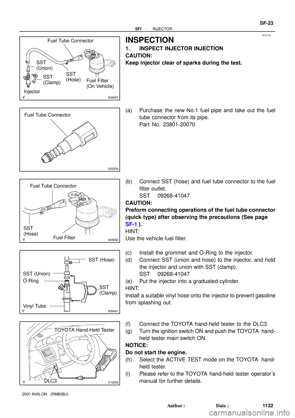
(a) Purchase the new No.1 fuel pipe and take out the fuel
tube connector from its pipe.
Part No. 23801-20070
(b) Connect SST (hose) and fuel tube connector to the fuel
filter outlet.
SST 09268-41047
CAUTION:
Preform connecting operations of the fuel tube connector
(quick type) after observing the precautions (See page
SF-1).
HINT:
Use the vehicle fuel filter.
(c) Install the grommet and O-Ring to the injector.
(d) Connect SST (union and hose) to the injector, and hold
the injector and union with SST (clamp).
SST 09268-41047
(e) Put the injector into a graduated cylinder.
HINT:
Install a suitable vinyl hose onto the injector to prevent gasoline
from splashing out.
(f) Connect the TOYOTA hand-held tester to the DLC3.
(g) Turn the ignition switch ON and push the TOYOTA hand-
held tester main switch ON.
NOTICE:
Do not start the engine.
(h) Select the ACTIVE TEST mode on the TOYOTA hand-
held tester.
(i) Please refer to the TOYOTA hand-held tester operator's
manual for further details.
Page 1648 of 1897

S05054
New Gasket
FI1654
Fulcrum Length
30 cm
SST
FI6372
CORRECT New O-Ring
Delivery Pipe
Injector Grommet
WRONG
B05295
O-Ring
Grommet
Spacer InsulatorDelivery Pipe
O-Ring
- SFISFI SYSTEM
SF-3
111 2 Author�: Date�:
2001 AVALON (RM808U)
(b) When connecting the union bolt on the high pressure pipe
union, observe the following procedures:
(1) Always use 2 new gaskets.
(2) Tighten the union bolt by hand.
(3) Tighten the union bolt to the specified torque.
Torque: 29 N´m (300 kgf´cm, 21 ft´lbf)
(c) When connecting the flare nut on the high pressure pipe
union, observe the following procedures:
(1) Apply a light coat of engine oil to the flare nut, and
tighten the flare nut by hand.
(2) Using SST, tighten the flare nut to specified torque.
SST 09023-12700
NOTICE:
Do not rotate the fuel pipe, when tightening the flare nut.
Torque: 28 N´m (285 kgf´cm, 21 ft´lbf)
HINT:
Use a torque wrench with a fulcrum length of 30 cm (11.81 in.).
(d) Observe the following precautions when removing and
installing the injectors.
(1) Never reuse the O-ring.
(2) When placing a new O-ring on the injector, take
care not to damage it in any way.
(3) Coat a new O-ring with spindle oil or gasoline be-
fore installing-never use engine, gear or brake oil.
(e) Install the injector to the delivery pipe and intake manifold
as shown in the illustration.
(f) Observe these precautions when disconnecting the fuel
tube connector (quick type).
(1) Check if there is any dirt like mud on the pipe and
around the connector before disconnecting them
and clean the dirt away.
(2) Be sure to disconnect with hands.
Page 1649 of 1897

S04583
S05040
Vinyl Bag
S05382
Retainer
S05050
Click Sound SF-4
- SFISFI SYSTEM
111 3 Author�: Date�:
2001 AVALON (RM808U)
(3) When the connector and the pipe are stuck, pinch
the retainer between the hands, push and pull the
connector to free to disconnect and pull it out. Do
not use any tool at this time.
(4) Inspect if there is any dirt or the likes on the seal sur-
face of the disconnected pipe and clean it away.
(5) Prevent the disconnected pipe and connector from
damaging and mixing foreign objects by covering
them with a vinyl bag.
(g) Observe these precautions when connecting the fuel
tube connector (quick type).
(1) Do not reuse the retainer removed from the pipe.
(2) Must use hands without using tools when to remove
the retainer from the pipe.
(3) Check if there is any damage or foreign objects on
the connected part of the pipe.
(4) Match the axis of the connector with axis of the pipe,
and push in the connector until the retainer makes
a ºclickº sound. In case that the connections is tight,
apply little amount of new engine oil on the tip of the
pipe.
(5) After having finished the connection, check if the
pipe and the connector are securely connected by
pulling them.
(6) Check if there is any fuel leakage.
(h) Observe these precautions when handling nylon tube.
(1) Pay attention not to turn the connector with force
when connecting them.
(2) Pay attention not to kink the nylon tube.
(3) Do not remove the EPDM protector on the outside
of the nylon tube.
(4) Must not close the piping with the nylon tube by
bending it.
Before installing the injector, must apply spindle oil
or gasoline on the place where a delivery pipe or an
intake manifold touches an O-ring of the injector.