Page 1032 of 1897
Evaporative Emission Control
System Malfunction
�Hose or tube cracked, holed, damaged or insufficient seal
�Fuel tank cap incorrectly install")
DI-16
- DIAGNOSTICSENGINE
172 Author�: Date�:
P0440
(DI-74)Evaporative Emission Control
System Malfunction
�Hose or tube cracked, holed, damaged or insufficient seal
�Fuel tank cap incorrectly installed
�Fuel tank cap cracked or damaged
�Vacuum hose cracked, holed, blocked, damaged or discon-
nected
�Fuel tank cracked, holed or damaged
�Charcoal canister cracked, holed or damaged
�Open or short in vapor pressure sensor circuit
�Vapor pressure sensor
�Fuel tank over fill check valve cracked or damaged
�ECM
��
P0441
(DI-80)Evaporative Emission Control
System Incorrect Purge Flow
�Vacuum hose cracked, holed blocked, damaged or discon-
nected ((1), (2), (3), (4), (5), (6), (7), (8), (9), (10) and (11) in
Fig. 1)
�Fuel tank cap incorrectly installed
�Fuel tank cap cracked or damaged
�Open or short in vapor pressure sensor circuit
�Vapor pressure sensor
�Open or short in VSV circuit for EVAP
�VSV for EVAP
�Open or short in VSV circuit for CCV
�VSV for CCV
�Open or short in VSV circuit for pressure switching valve
�VSV for pressure switching valve
�Fuel tank cracked, holed or damaged
�Charcoal canister cracked, holed or damaged
�Fuel tank over fill check valve cracked or damaged
�ECM
��
P0442
(DI-74)Evaporative Emission Control
System Leak Detected (Small
Leak)
�Same as DTC No. P0440��
P0446
(DI-80)Evaporative Emission Control
System Vent Control Malfunction�Same as DTC No. P0441��
P0450
(DI-97)Evaporative Emission Control
System Pressure Sensor Mal-
function
�Open or short in vapor pressure sensor circuit
V��
P0451
(DI-97)Evaporative Emission Control
System Pressure Sensor Range/
Performance�Vapor pressure sensor
�ECM��
P0500
(DI-99)Vehicle Speed Sensor Malfunc-
tion�Combination meter
�Open or short in speed sensor circuit
�ECM
��
P0505
(DI-102)Idle Control System Malfunction
�Open or short in IAC valve circuit
�IAC valve is stuck or closed
�Open or short in A/C signal circuit
�Air induction system
�ECM
��
*1: MIL lights up
*2: MIL light up or blinking
Page 1273 of 1897
 CONTROL SYSTEM
1100 Author�: Date�:
2001 AVALON (RM80")
EC0B4-03
B01082
Gasket
B06544
Vacuum
Gauge
A10838
TOYOTA Hand-Held Tester
DLC3
B06722
Battery EC-6
- EMISSION CONTROLEVAPORATIVE EMISSION (EVAP) CONTROL SYSTEM
1100 Author�: Date�:
2001 AVALON (RM808U)
INSPECTION
1. VISUALLY INSPECT LINES AND CONNECTORS
Visually check for loose connections, sharp bends or damage.
2. VISUALLY INSPECT FUEL TANK FILLER PIPE
Visually check for deformation, cracks or fuel leakage.
3. INSPECT FUEL TANK CAP
Visually check if the cap and/or gasket are deformed or dam-
aged.
If necessary, repair or replace the cap.
4. INSPECT EVAP SYSTEM LINE
(a) Warm up the engine and stop the engine.
Allow the engine to warm up to normal operating tempera-
ture.
(b) Install a vacuum gauge (EVAP control system test equip-
ment vacuum gauge) to the EVAP service port on the
purge line.
(c) TOYOTA Hand-Held Tester:
Forced driving of the VSV for the EVAP.
(1) Connect a TOYOTA hand-held tester to the DLC3.
(2) Start the engine.
(3) Push the TOYOTA hand-held tester main switch
ON.
(4) Use the ACTIVE TEST mode on the TOYOTA
hand-held tester to operate the VSV for the EVAP.
(d) If you have no TOYOTA Hand-Held Tester:
Forced driving of the VSV for the EVAP.
(1) Disconnect the VSV connector for the EVAP.
(2) Connect the positive (+) and negative (-) leads from
the battery to the VSV terminals for the EVAP.
(3) Start the engine.
Page 1275 of 1897
 CONTROL SYSTEM")
B06547
Fuel Tank Cap
B08623
Air
Disconnect
EVAP Line Hose
B08624Air
Disconnect
Cap
Disconnect
EVAP Line HosePurge Line
Hose
Purge Port
EC-8
- EMISSION CONTROLEVAPORATIVE EMISSION (EVAP) CONTROL SYSTEM
1102 Author�: Date�:
2001 AVALON (RM808U)
(3) Check if the pressure decreases when the fuel tank
cap is removed while adding pressure.
HINT:
If the pressure does not decrease when the filler cap is re-
moved, then you can conclude that the hose connecting the
service port to the fuel tank is blocked, etc.
(k) Disconnect the pressure gauge from the EVAP service
port on the purge line.
5. CHECK AIRTIGHTNESS IN FUEL TANK AND FILLER
PIPE
(a) Disconnect the EVAP line hose from the charcoal canister
side and then pressurize and make the internal pressure
in the fuel tank 4 kPa (41 gf/cm
2, 0.58 psi).
(b) Check that the internal pressure of the fuel tank can be
hold for 1 minute.
(c) Check the connected portions of each hose and pipe.
(d) Check the installed parts on the fuel tank.
If there is no abnormality, replace the fuel tank and filler pipe.
(e) Reconnect the EVAP line hose to the charcoal canister.
6. INSPECT FUEL CUTOFF VALVE AND FILL CHECK
VA LV E
(a) Disconnect the purge line hose and EVAP line hose from
the charcoal canister.
(b) Plug the cap to the air drain hose.
(c) Pressurize 4 kPa (41 gf/cm
2, 0.58 psi) to the purge port
and check that there is ventilation through the EVAP line
hose.
HINT:
In the condition that the fuel fuel is full, as the float value of the
fill check valve is closed and has no ventilation, it is necessary
to check the fuel amount (volume).
(d) Check if there is any struck in the vent line hose and EVAP
line hose.
If there is no stuck in hoses, replace the fuel cutoff valve and fill
check valve.
(e) Reconnect the purge line hose and EVAP line hose to the
charcoal canister.
Page 1276 of 1897
 CONTROL SYSTEM
EC-9")
B08625AirDisconnect
Air Inlet
Line Hose
B01253
Pinch
Push
AA
Pinch
B08620
B08621
Purge Port
Vent Port
Cap EVAP Port
Air Drain Port
Air
- EMISSION CONTROLEVAPORATIVE EMISSION (EVAP) CONTROL SYSTEM
EC-9
1103 Author�: Date�:
2001 AVALON (RM808U)
7. CHECK AIR INLET LINE
(a) Disconnect the air inlet line hose from the charcoal canis-
ter.
(b) Check that there is ventilation in the air inlet line.
(c) Reconnect the air inlet line hose to the charcoal canister.
8. REMOVE CHARCOAL CANISTER ASSEMBLY
(a) Disconnect the VSV connector for the pressure switching
valve.
(b) Disconnect the vapor pressure sensor connector.
(c) Disconnect the fuel hose from the vapor pressure sensor.
(d) Disconnect the purge line hose, EVAP line hose and air
inlet line hose from the charcoal canister.
(e) Disconnect the vent line hose from the charcoal canister.
(1) Push the connector deep inside.
(2) Pinch portion A.
(3) Pull out the connector.
(f) Remove the 2 charcoal canister mounting bolts.
(g) Remove the vapor pressure sensor mounting bolt.
(h) Remove the charcoal canister assembly.
9. INSPECT CHARCOAL CANISTER
(a) Visually check the charcoal canister for cracks or dam-
age.
(b) Inspect the charcoal canister operation.
(1) Plug the vent port with the cap.
(2) While holding the purge port closed, blow air (1.76
kPa, 18 gf/cm
2, 0.26 psi) into the EVAP port and
check that air flows from the air drain port.
Page 1280 of 1897
EC04L-03
B07254
Vent LineCharcoal Canister
Fuel Tank
EVAP Line
Air Drain Hose
Filler Pipe
Air Inlet Line
Purge Line
Cut Off Valve
Fill Check Valve
VSV for EVAPVacuum Surge TankEVAP Service Port
Vapor Pressure Sensor
Fuel Tank Cap
VSV for Pressure Switching Valve PCV Valve
VSV for Canister Closed Valve (CCV)
EC-2
- EMISSION CONTROLPARTS LAYOUT AND SCHEMATIC DRAWING
1096 Author�: Date�:
2001 AVALON (RM808U)
PARTS LAYOUT AND SCHEMATIC DRAWING
LOCATION
Page 1469 of 1897
MA01M-02
P00495
Inside Outside
- MAINTENANCEENGINE
MA-5
47 Author�: Date�:
2001 AVALON (RM808U)
ENGINE
INSPECTION
HINT:
Inspect these items when the engine is cold.
1. REPLACE TIMING BELT (See page EM-15)
2. INSPECT DRIVE BELTS
(See pages CH-1, SR-3 and AC-17)
3. REPLACE SPARK PLUGS (See page IG-1)
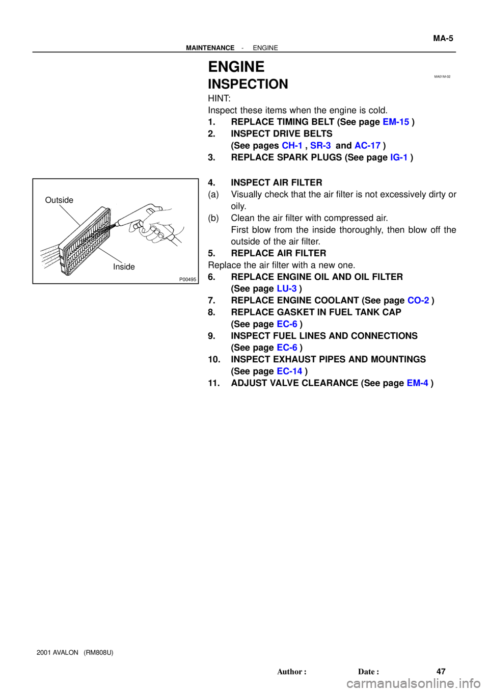
4. INSPECT AIR FILTER
(a) Visually check that the air filter is not excessively dirty or
oily.
(b) Clean the air filter with compressed air.
First blow from the inside thoroughly, then blow off the
outside of the air filter.
5. REPLACE AIR FILTER
Replace the air filter with a new one.
6. REPLACE ENGINE OIL AND OIL FILTER
(See page LU-3)
7. REPLACE ENGINE COOLANT (See page CO-2)
8. REPLACE GASKET IN FUEL TANK CAP
(See page EC-6)
9. INSPECT FUEL LINES AND CONNECTIONS
(See page EC-6)
10. INSPECT EXHAUST PIPES AND MOUNTINGS
(See page EC-14)
11. ADJUST VALVE CLEARANCE (See page EM-4)
Page 1519 of 1897
PP0RX-01
- PREPARATIONLUBRICATION
PP-19
69 Author�: Date�:
2001 AVALON (RM808U)
LUBRICANT
ItemCapacityClassification
Engine oil
Dry fill
Drain and refill
w/ Oil filter change
w/o Oil filter change
5.2 liters (5.5 US qts, 4.6 lmp. qts)
4.7 liters (5.0 US qts, 4.1 lmp. qts)
4.5 liters (4.8 US qts, 4.0 lmp. qts)
API grade SH Energy-Conserving II or SJ, Ener-
gy-Conserving or ILSAC multigrade engine oil.
SAE 5W-30 is the best choice for your vehicle,
for good fuel economy and good starting in cold
weather.
Page 1567 of 1897

TORQUE SPECIFICATION
Part tightenedN´mkgf´cmft´lbf
Timing belt plate x Oil pump88069 in.´lbf
No.1")
SS0EG-02
- SERVICE SPECIFICATIONSENGINE MECHANICAL
SS-9
125 Author�: Date�:
2001 AVALON (RM808U)
TORQUE SPECIFICATION
Part tightenedN´mkgf´cmft´lbf
Timing belt plate x Oil pump88069 in.´lbf
No.1 idler pulley x Oil pump3435025
No.2 idler pulley x No.2 idler pulley bracket4344032
Camshaft timing pulley x Camshaft
for SST125
881,300
90094
65
Timing belt tensioner x Oil pump2728020
RH engine mounting bracket x Cylinder block2829021
No.2 timing belt cover x No.3 timing belt cover8.58574 in.´lbf
No.1 timing belt cover x Oil pump8.58574 in.´lbf
Crankshaft pulley x Crankshaft2152,200159
No.2 generator bracket x Engine RH mounting bracket2829021
Cylinder head x Cylinder block 12 pointed head 1st
2nd
Recessed head54
Turn 90°
18.5550
Turn 90°
18540
Turn 90°
13
Camshaft bearing cap x Cylinder head1616012
Cylinder head cover x Cylinder head88069 in.´lbf
Exhaust manifold x Cylinder head4950036
Exhaust manifold stay x Exhaust manifold California
Except California34
20350
20025
15
Exhaust manifold stay x Transmission housing California
Except California34
20350
20025
15
No.1 EGR pipe x RH exhaust manifold121209
No.1 EGR pipe x EGR cooler121209
PS pump bracket x RH cylinder head4344032
Oil dipstick guide x LH cylinder head88069 in.´lbf
Water inlet pipe x LH cylinder head19.520014
Cylinder head rear plate x LH cylinder head88069 in.´lbf
No.3 timing belt cover x Cylinder head8.58574 in.´lbf
Water outlet x Intake manifold1515011
Fuel inlet hose x Fuel filter2930021
Intake manifold x Cylinder head1515011
Air intake chamber x Intake manifold4344032
No.2 EGR pipe x Air intake chamber121209
No.2 EGR pipe x EGR cooler121209
No.1 engine hanger x Air intake chamber3940029
No.1 engine hanger x RH cylinder head3940029
Air intake chamber stay x Air intake chamber19.520014
Air intake chamber stay x RH cylinder head19.520014
Main bearing cap x Cylinder block 12 pointed head 1st
2nd
6 pointed head22
Turn 90°
27225
Turn 90°
27516
Turn 90°
20
Connecting rod cap x Connecting rod 1st
2nd24.5
Turn 90°250
Turn 90°18
Turn 90°
Rear oil seal retainer x Cylinder block88069 in.´lbf
EGR cooler x Cylinder block99078 in.´lbf