Page 719 of 1897

DIAGNOSTIC TROUBLE CODE CHART
NOTICE:
�When removing the part, turn the ignition switch OF")
DI6NT-03
DI-258
- DIAGNOSTICSABS WITH EBD & BA & TRAC & VSC SYSTEM
414 Author�: Date�:
2001 AVALON (RM808U)
DIAGNOSTIC TROUBLE CODE CHART
NOTICE:
�When removing the part, turn the ignition switch OFF.
�When replacing the steering angle sensor or ECU, make sure to perform steering angle sensor
zero point calibration.
HINT:
�Using SST 09843-18020, connect the terminals Tc and E1.
�If any abnormality is not found when inspecting parts, inspect the ECU.
�If a malfunction code is displayed during the DTC check, check the circuit corresponding the code. For
details of each code, refer to the page under respective ºDTC No.º in the DTC chart.
DTC chart of ABS system:
DTC No.
(See Page)Detection ItemTrouble Area
C0278 / 11
(DI-280)Open or short circuit in ABS solenoid relay circuit�ABS solenoid relay
�ABS solenoid relay circuit
C0273 / 13
(DI-276)Open or short circuit in ABS motor relay circuit�ABS motor relay
�ABS motor relay circuit
C0226 / 21
(DI-273)Open or short circuit in brake actuator�Brake actuator
�SFRR or SFRH circuit
C0236 / 22
(DI-273)Open or short circuit in brake actuator�Brake actuator
�SFLR or SFLH circuit
C0246 / 23
(DI-273)Open or short circuit in brake actuator�Brake actuator
�SRRR or SRRH circuit
C0256 / 24
(DI-273)Open or short circuit in brake actuator�Brake actuator
�SRLR or SRLH circuit
C0200 / 31*
(DI-267)Right front wheel speed sensor signal malfunction
C0205 / 32*
(DI-267)Left front wheel speed sensor signal malfunction�Right front, left front, right rear and left rear speed sensor
Eh d i itC0210 / 33*
(DI-267)Right rear wheel speed sensor signal malfunction
�Each speed sensor circuit
�Speed sensor rotor
C0215 / 34*
(DI-267)Left rear wheel speed sensor signal malfunction
C1330 / 35*
(DI-267)Open circuit in right front speed sensor circuit�Right front speed sensor
�Right front speed sensor circuit
C1331 / 36*
(DI-267)Open circuit in left front speed sensor circuit�Left front speed sensor
�Left front speed sensor circuit
C1237 / 37
(DI-295)Front tires are different from rear in size.�Tire size
�Speed sensor rotor
C1332 / 38*
(DI-267)Open circuit in right rear speed sensor circuit�Right rear speed sensor
�Right rear speed sensor circuit
C1333 / 39*
(DI-267)Open circuit in left rear speed sensor circuit�Left rear speed sensor
�Left rear speed sensor circuit
C1241 / 41
(DI-297)Low battery positive voltage or abnormally high battery positive
voltage�Battery
�Charging system
�Power source circuit
C1249 / 58
(DI-303)Open circuit in stop light switch circuit�Stop light switch
�Stop light switch circuit
Page 1467 of 1897
B00632
MA01N-01
MA-6
- MAINTENANCEBRAKE
48 Author�: Date�:
2001 AVALON (RM808U)
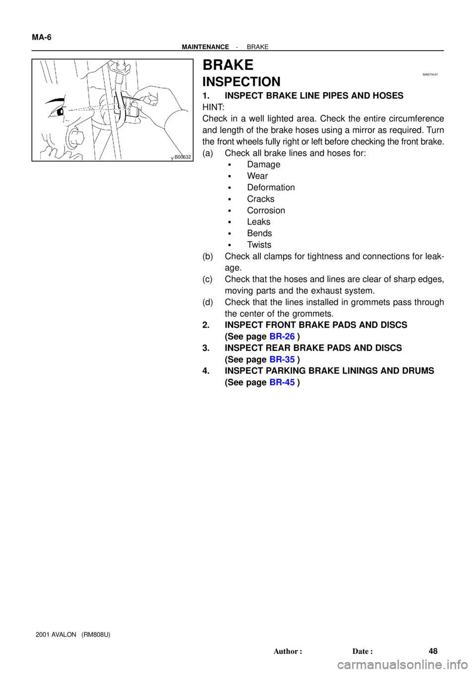
BRAKE
INSPECTION
1. INSPECT BRAKE LINE PIPES AND HOSES
HINT:
Check in a well lighted area. Check the entire circumference
and length of the brake hoses using a mirror as required. Turn
the front wheels fully right or left before checking the front brake.
(a) Check all brake lines and hoses for:
�Damage
�Wear
�Deformation
�Cracks
�Corrosion
�Leaks
�Bends
�Twists
(b) Check all clamps for tightness and connections for leak-
age.
(c) Check that the hoses and lines are clear of sharp edges,
moving parts and the exhaust system.
(d) Check that the lines installed in grommets pass through
the center of the grommets.
2. INSPECT FRONT BRAKE PADS AND DISCS
(See page BR-26)
3. INSPECT REAR BRAKE PADS AND DISCS
(See page BR-35)
4. INSPECT PARKING BRAKE LININGS AND DRUMS
(See page BR-45)
Page 1468 of 1897

CHASSIS
INSPECTION
1. INSPECT STEERING LINKAGE
(a) Check the steering wheel free-play (See page SR-8).
(b) Check the")
MA01O-02
B08915
- MAINTENANCECHASSIS
MA-7
49 Author�: Date�:
2001 AVALON (RM808U)
CHASSIS
INSPECTION
1. INSPECT STEERING LINKAGE
(a) Check the steering wheel free-play (See page SR-8).
(b) Check the steering linkage for looseness or damage.
Check that:
�Tie rod ends do not have excessive play.
�Dust seals and boots are not damaged.
�Boot clamps are not loose.
2. INSPECT SRS AIRBAG (See pages RS-15, RS-30)
3. INSPECT STEERING GEAR HOUSING OIL
Check the steering gear housing for oil leakage.
4. INSPECT DRIVE SHAFT BOOTS
Check the drive shaft boots for clamp looseness, leakage or
damage.
5. INSPECT BALL JOINTS AND DUST COVERS
(a) Inspect the ball joints for excessive looseness.
�Jack up the front of the vehicle and place wooden
blocks with a height of 180 - 200 mm (7.09 - 7.87
in.) under the front tires.
�Lower the jack until there is about half a load on the
front coil spring. Place stands under the vehicle for
safety.
�Check that the front wheels are pointing straight
ahead, and block them with chocks.
�Using a lever, pry up the end of the lower arm, and
check the amount of play.
Maximum ball joint vertical play: 0 mm (0 in.)
If there is play, replace the ball joint.
(b) Check the dust cover for damage.
6. CHECK TRANSAXLE FLUID
Visually check the transaxle for fluid leakage.
If leakage is found, check for the cause and repair.
7. REPLACE TRANSAXLE FLUID (See page DI-160)
Page 1474 of 1897

OUTSIDE VEHICLE
GENERAL MAINTENANCE
These are maintenance and inspection items which are considered to be the owner")
MA001-12
- MAINTENANCEOUTSIDE VEHICLE
MA-1
43 Author�: Date�:
2001 AVALON (RM808U)
OUTSIDE VEHICLE
GENERAL MAINTENANCE
These are maintenance and inspection items which are considered to be the owner's responsibility.
They can be done by the owner or they can have them done at a service shop.
These items include those which should be checked on a daily basis, those which, in most cases, do not
require (special) tools and those which are considered to be reasonable for the owner to do.
Items and procedures for general maintenance are as follows.
1. GENERAL NOTES
�Maintenance items may vary from country to country. Check the owner's manual supplement in which
the maintenance schedule is shown.
�Every service item in the periodic maintenance schedule must be performed.
�Periodic maintenance service must be performed according to whichever interval in the periodic main-
tenance schedule occurs first, the odometer reading (miles) or the time interval (months).
�Maintenance service after the last period should be performed at the same interval as before unless
otherwise noted.
�Failure to do even one item an cause the engine to run poorly and increase exhaust emissions.
2. TIRES
(a) Check the pressure with a gauge. If necessary, adjust.
(b) Check for cuts, damage or excessive wear.
3. WHEEL NUTS
When checking the tires, check the nuts for looseness or for missing nuts. If necessary, tighten them.
4. TIRE ROTATION
Check the owner's manual supplement in which the maintenance schedule is shown.
5. WINDSHIELD WIPER BLADES
Check for wear or cracks whenever they do not wipe clean. If necessary, replace.
6. FLUID LEAKS
(a) Check underneath for leaking fuel, oil, water or other fluid.
(b) If you smell gasoline fumes or notice any leak, have the cause found and corrected.
7. DOORS AND ENGINE HOOD
(a) Check that all doors including the trunk lid operate smoothly, and that all latches lock securely.
(b) Check that the engine hood secondary latch secures the hood from opening when the primary latch
is released.
Page 1489 of 1897
PP0AZ-04
- PREPARATIONBODY
PP-59
109 Author�: Date�:
2001 AVALON (RM808U)
EQUIPMENT
Clip remover
Torque wrench
Hog ring pliers
TapeTo avoid surface damage
Adhesive tapeTo avoid surface damage
Double-stick tape
Adhesive
Cleaner
Shop rag
Knife
Sealer gun
Brush
Putty spatula
Glass plate or similar object
Wooden block or similar object
Heat light
Piano wire
Tire Width: 185 mm (7.28 in.) Inner diam: 360 mm (14.17 in.)Seat belt pretensioner
Tire with disk wheel Width: 185 mm (7.28 in.)
Inner diam: 360 mm (14.17 in.)Seat belt pretensioner
Vinyl bagSeat belt pretensioner
Page 1494 of 1897
PP0AZ-04
- PREPARATIONBODY
PP-59
109 Author�: Date�:
2001 AVALON (RM808U)
EQUIPMENT
Clip remover
Torque wrench
Hog ring pliers
TapeTo avoid surface damage
Adhesive tapeTo avoid surface damage
Double-stick tape
Adhesive
Cleaner
Shop rag
Knife
Sealer gun
Brush
Putty spatula
Glass plate or similar object
Wooden block or similar object
Heat light
Piano wire
Tire Width: 185 mm (7.28 in.) Inner diam: 360 mm (14.17 in.)Seat belt pretensioner
Tire with disk wheel Width: 185 mm (7.28 in.)
Inner diam: 360 mm (14.17 in.)Seat belt pretensioner
Vinyl bagSeat belt pretensioner
Page 1524 of 1897
PP0MS-01
PP-52
- PREPARATIONSUPPLEMENTAL RESTRAINT SYSTEM
102 Author�: Date�:
2001 AVALON (RM808U)
EQUIPMENT
Torque wrench
Bolt: Length: 35 mm (1.38 in.) Pitch: 1.0 mm (0.039 in.)
Diam.: 6.0 mm (0.236 in.)Airbag disposal
Tire Width: 185 mm (7.28 in.) Inner diam.: 360mm (14.17 in.)Airbag disposal
Tire with disc wheel Width: 185 mm (7.28 in.)
Inner diam.: 360 mm (14.17 in.)Airbag disposal
Vinyl bagAirbag disposal
Page 1576 of 1897

SUSPENSION AND AXLE
SERVICE DATA
Cold tire inflation
pressureP205/65R15 92H Front, rear
P205/60R16")
SS04W-07
- SERVICE SPECIFICATIONSSUSPENSION AND AXLE
SS-27
143 Author�: Date�:
2001 AVALON (RM808U)
SUSPENSION AND AXLE
SERVICE DATA
Cold tire inflation
pressureP205/65R15 92H Front, rear
P205/60R16 91H Front, rear210 kPa (2.1 kgf/cm2, 31 psi)
220 kPa (2.2 kgf/cm2, 32 psi)
Vehicle heightFront*1
Rear*2213 mm (8.39 in.)
266 mm (10.47 in.)
Camber
Right-left error-0°37' ± 45' (-0.62° ± 0.75°)
45' (0.75°) or less
Front Wheel
Caster
Right-left error2°10' ± 45' (2.17° ± 0.75°)
45' (0.75°) or less
Front Wheel
alignmentSteering axis inclination
Right-left error13°04' ± 45' (13.07° ± 0.75°)
45' (0.75°) or less
Toe-in (total)
Rack end length difference0° ± 12' (0° ± 0.2°, 0 ± 2 mm, 0 ± 0.08 in.)
1.5 mm (0.059 in.) or less
Wheel angle Inside wheel
Outside wheel: Reference35°45' ± 1° (35.75° ± 1°)
31°23' (31.38°)
Rear wheel
Camber
Right-left error-0°43' ± 45' (-0.72° ± 0.75°)
45' (0.75°) or less
Rear wheel
alignmentToe-in (total)
No. 2 lower suspension arm length difference0°24' ± 12' (0.4° ± 0.2°, 4 ± 2 mm, 0.16 ± 0.08 in.)
1 mm (0.04 in.) or less
FtlAxle bearing backlash Maximum0.05 mm (0.0020 in.)Front axleAxle hub deviationMaximum0.05 mm (0.0020 in.)
Front drive shaftDrive shaft standard length LH
RH586.0 ± 2.0 mm (23.071 ± 0.079 in.)
881.6 ± 2.0 mm (34.709 ± 0.079 in.)
Ft iLower ball joint turning torque1.0 - 3.4 N´m (10 - 35 kgf´cm, 8.7 - 30 in.´lbf)Front suspensionStabilizer bar link ball joint turning torque0.05 - 1.0 N´m (0.5 - 10 kgf´cm, 0.4 - 8.7 in.´lbf)
RlAxle bearing backlash Maximum0.05 mm (0.0020 in.)Rear axleAxle hub deviationMaximum0.07 mm (0.0028 in.)
RiNo. 2 lower suspension arm length512.3 mm (20.169 in.)Rear suspensionStabilizer bar link ball joint turning torque0.05 - 1.0 N´m (0.5 - 10 kgf´cm, 0.4 - 8.7 in.´lbf)
*1: Front measuring point
Measure the distance from the ground to the center of the front side lower suspension arm mounting bolt.
*2: Rear measuring point
Measure the distance from the ground to the center of the front side strut rod mounting bolt.