Page 1351 of 1897

(d) Remove the 9 bolts, 2 nuts, 2 plate washers, the intake
manif")
A07428
P20049Gasket
A05077
Clamp
Clamp
Clamp
A10531
- ENGINE MECHANICALCYLINDER HEAD
EM-33
1017 Author�: Date�:
2001 AVALON (RM808U)
(d) Remove the 9 bolts, 2 nuts, 2 plate washers, the intake
manifold, delivery pipes and injectors assembly.
NOTICE:
�Be careful not to drop the injectors when removing
the delivery pipes.
�Pay attention to put any hung load on the injector to
and from the side direction.
10. REMOVE WATER OUTLET
(a) Disconnect the ECT sender gauge connector.
(b) Disconnect the ECT sensor connector.
(c) Disconnect the ground strap connector.
(d) Disconnect the upper radiator hose.
(e) Disconnect the engine coolant reservoir hose.
(f) Remove the 2 bolts, 2 nuts and 2 plate washers.
(g) Disconnect the water bypass hose, and remove the water
outlet.
(h) Remove the 2 gaskets.
11. REMOVE IGNITION COILS
12. REMOVE SPARK PLUGS
13. REMOVE TIMING BELT (See page EM-15)
14. REMOVE CAMSHAFT TIMING PULLEYS
(See page EM-15)
15. REMOVE NO.2 IDLER PULLEY (See page EM-15)
16. REMOVE NO.3 TIMING BELT COVER
(a) Disconnect the 3 engine wire clamps from the timing belt
cover.
(b) Remove the 6 bolts and timing belt cover.
17. REMOVE CAMSHAFT POSITION SENSORS
18. REMOVE CAMSHAFT TIMING OIL CONTROL VALVES
19. DISCONNECT ENGINE WIRE PROTECTOR FROM
REAR SIDE
Remove the nut, and disconnect the engine wire protector from
the RH cylinder head.
Page 1360 of 1897

(d) Align the knock pin and knock pin groove and install VVT-
i on the camshaft.
NO")
A05706
Align
A05738
A05245
A05243
EM-54
- ENGINE MECHANICALCYLINDER HEAD
1038 Author�: Date�:
2001 AVALON (RM808U)
(d) Align the knock pin and knock pin groove and install VVT-
i on the camshaft.
NOTICE:
Install it under the condition that the lock pin is operated
and lock at the maximum delay angle position.
(e) Apply the engine oil on the nut, the placing surface of
VVT-i and the screw portion.
HINT:
Be sure to apply the oil, otherwise the prescribed torque cannot
be obtained.
(f) Using a 46 mm socket wrench, install and torque a new
lock nut by turning it counterclockwise.
Torque: 150 N´m (1,530 kgf´cm, 110 ft´lbf)
NOTICE:
�Must change the nuts to the new ones when to change
VVT-i.
�The lock nut have LH threads.
�Never use any tool other than the socket wrench,
otherwise that may result in deforming the cam angle
rotor portion.
3. REPLACE SPARK PLUG TUBE GASKETS
(a) Bend up the tab on the ventilation baffle plate which pre-
vents the gasket from the slipping out.
(b) Using a screwdriver and hammer, tap out the gasket.
(c) Using needle-nose pliers, pry out the gasket.
Page 1366 of 1897

7. INSTALL ENGINE MOUNTING ABSORBER
Install the engine mounting a")
A07431
P18752
A07430
P18775
A10833
BracketA
B
A
A
C
A EM-78
- ENGINE MECHANICALENGINE UNIT
1062 Author�: Date�:
2001 AVALON (RM808U)
7. INSTALL ENGINE MOUNTING ABSORBER
Install the engine mounting absorber with the 4 bolts.
Torque: 48 N´m (490 kgf´cm, 35 ft´lbf)
8. CONNECT REAR ENGINE MOUNTING INSULATOR
(a) Connect the mounting insulator with the 4 nuts.
Torque: 66 N´m (670 kgf´cm, 48 ft´lbf)
(b) Install the 2 hole plugs.
9. CONNECT LH ENGINE MOUNTING INSULATOR
Connect the mounting insulator with the 4 bolts.
Torque: 64 N´m (650 kgf´cm, 47 ft´lbf)
10. REMOVE ENGINE SLING DEVICE
11. CONNECT TRANSAXLE CONTROL CABLE TO
TRANSAXLE
12. INSTALL PS PUMP
(a) Install the PS pump with the 2 bolts.
Torque: 43 N´m (440 kgf´cm, 31 ft´lbf)
(b) Install the drive belt.
(c) Connect the PS pressure tube with the 2 nuts.
13. INSTALL A/C COMPRESSOR
(a) Install the A/C compressor and drive belt adjusting bar
bracket with the 5 bolts and nut.
Torque:
25 N´m (250 kgf´cm, 18 ft´lbf) for bolt A
18 N´m (185 kgf´cm, 13 ft´lbf) for bolt B
25 N´m (250 kgf´cm, 18 ft´lbf) for nut C
(b) Install the drive belt.
(c) Connect the A/C compressor connector.
14. INSTALL DRIVE SHAFTS (See page SA-24)
Page 1371 of 1897
P18752
A07431
A07432
A07433
Engine
Hanger
EM-74
- ENGINE MECHANICALENGINE UNIT
1058 Author�: Date�:
2001 AVALON (RM808U)
19. DISCONNECT REAR ENGINE MOUNTING BRACKET
FROM FRONT FRAME
(a) Remove the 2 hole plugs.
(b) Remove the 4 nuts holding the front frame to the mount-
ing bracket.
20. REMOVE ENGINE MOUNTING ABSORBER
Remove the 4 bolts and mounting absorber.
21. DISCONNECT FRONT ENGINE MOUNTING INSULA-
TOR FROM FRONT FRAME
Remove the 3 bolts holding the mounting insulator to the front
frame.
22. ATTACH ENGINE SLING DEVICE TO ENGINE HANG-
ERS
(a) Install the No.2 engine hanger in the correct direction.
Part No.:
No.2 engine hanger12282-20020
Bolt90080-1 1331
Torque: 19.5 N´m (200 kgf´cm, 14 ft´lbf)
(b) Attach the sling device to the engine hangers.
CAUTION:
Do not attempt to hang the engine by hooking the chain to
any other part.
Page 1401 of 1897
IG0DM-02
A10518
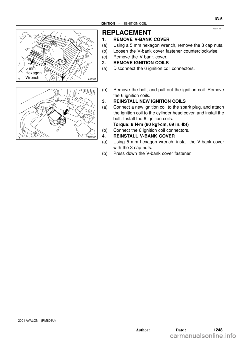
5 mm
Hexagon
Wrench
B06515
- IGNITIONIGNITION COIL
IG-5
1248 Author�: Date�:
2001 AVALON (RM808U)
REPLACEMENT
1. REMOVE V-BANK COVER
(a) Using a 5 mm hexagon wrench, remove the 3 cap nuts.
(b) Loosen the V-bank cover fastener counterclockwise.
(c) Remove the V-bank cover.
2. REMOVE IGNITION COILS
(a) Disconnect the 6 ignition coil connectors.
(b) Remove the bolt, and pull out the ignition coil. Remove
the 6 ignition coils.
3. REINSTALL NEW IGNITION COILS
(a) Connect a new ignition coil to the spark plug, and attach
the ignition coil to the cylinder head cover, and install the
bolt. Install the 6 ignition coils.
Torque: 8 N´m (80 kgf´cm, 69 in.´lbf)
(b) Connect the 6 ignition coil connectors.
4. REINSTALL V-BANK COVER
(a) Using 5 mm hexagon wrench, install the V-bank cover
with the 3 cap nuts.
(b) Press down the V-bank cover fastener.
Page 1466 of 1897

BODY
INSPECTION
1. TIGHTEN BOLTS AND NUTS ON CHASSIS AND BODY
Tighten the following parts:
�Front s")
MA0676B00995
MA01P-02
B08916
B09029
MA-8
- MAINTENANCEBODY
50 Author�: Date�:
2001 AVALON (RM808U)
BODY
INSPECTION
1. TIGHTEN BOLTS AND NUTS ON CHASSIS AND BODY
Tighten the following parts:
�Front seat mount bolts
Torque: 37 N´m (375 kgf´cm, 27 ft´lbf)
�Front suspension member-to-body mounting bolts
Torque: 181 N´m (1,850 kgf´cm, 134 ft´lbf)
�Rear suspension member-to-body mounting nuts
Torque: 51 N´m (520 kgf´cm, 38 ft´lbf)
2. FINAL INSPECTION
(a) Check the operation of the body parts:
�Hood:
Auxiliary catch operates properly
Hood locks securely when closed
�Front and rear doors:
Door lock operates properly
Doors close properly
�Luggage compartment door:
Door lock operates properly
�Seats:
Seat adjusts easily and locks securely in any posi-
tion
Front seat back locks securely in any position
Folding-down rear seat backs lock securely
(b) Road test:
�Check the engine and chassis for abnormal noises.
�Check that the vehicle dose not wander or pull to
one side.
�Check that the brakes work properly and do not
drag.
�Do setting of the parking brake shoes and drum.
(c) Be sure to deliver a clean car and especially check:
�Steering wheel
�Shift lever knob
�All switch knobs
�Door handles
�Seats
Page 1551 of 1897

TORQUE SPECIFICATION
Part tightenedN´mkgf´cmft´lbf
Front side engine mounting insulator x Front")
SS0BM-04
- SERVICE SPECIFICATIONSAUTOMATIC TRANSAXLE
SS-25
141 Author�: Date�:
2001 AVALON (RM808U)
TORQUE SPECIFICATION
Part tightenedN´mkgf´cmft´lbf
Front side engine mounting insulator x Front frame assembly8082059
Rear engine mounting insulator x Front frame assembly6667048
LH transaxle mounting insulator x Front frame assembly8082059
Engine mounting insulator x Front frame assembly4849035
Transaxle x Engine 17 mm bolt
14 mm bolt66
48670
49048
35
Torque converter clutch x Drive plate4142030
Valve body x Transaxle case1111 08
Oil strainer x Valve body Bolt A
(See page AX-35) Bolt B10
11100
11 07
8
Oil pan x Transaxle case7.88069 in.´lbf
Oil pan drain plug4950036
Park/Neutral position switch x Transaxle case Bolt
Nut5.4
6.955
7048 in.´lbf
61 in.´lbf
Connector clamp x Valve body6.66758 in.´lbf
Manual valve body x Transaxle case1111 08
Line pressure test plug x Transaxle case7.58069 in.´lbf
Detent spring x Manual valve body1111 08
Oil pipe bracket x Transaxle case101007
Steering gear housing x Front frame assembly1811,850134
Stabilizer bar bracket x Front frame assembly1919514
Stabilizer bar link x Stabilizer bar3940029
Lower suspension arm x Lower ball joint1271,30094
Tie rod end x Steering knuckle4950036
Drive shaft lock nut2943,000217
Direct clutch speed sensor x Transaxle case1111 08
Exhaust manifold bracket x Transaxle case2020015
Exhaust manifold plate2020015
Front frame assembly x Body 19 mm bolt
14 mm bolt
Nut181
32
361,850
330
370134
24
27
Front exhaust pipe x Exhaust center pipe4344032
Exhaust manifold x Front exhaust pipe6263046
Exhaust front pipe support stay x Exhaust front pipe support bracket3333024
Starter x Torque converter clutch housing3940029
Transaxle control shaft lever x Park/neutral position switch1515011
Throttle cable adjusting nut1515011
Drive plate x Crankshaft8385061
Shift control cable x Transaxle control shaft lever1515011
Throttle cable retaining plate set bolt5.45548 in.´lbf
Shift solenoid valve No. 1, No. 2, SL, SLN x Valve body6.66758 in.´lbf
Front wheel nut1031,05076
Exhaust front pipe support bracket x Body2121015
PS reservoir pipe x Front frame101007
Page 1555 of 1897

BODY
TORQUE SPECIFICATION
Part tightenedN´mkgf´cmft´lbf
FRONT BUMPER---
Front bumper upper reinforcement x Bo")
SS0G3-06
- SERVICE SPECIFICATIONSBODY
SS-37
153 Author�: Date�:
2001 AVALON (RM808U)
BODY
TORQUE SPECIFICATION
Part tightenedN´mkgf´cmft´lbf
FRONT BUMPER---
Front bumper upper reinforcement x Body1111 58
Front bumper upper reinforcement x Side support5.45548 in.´lbf
Side support x Body1111 58
Front bumper reinforcement x Body131309
Front bumper cover x Body5.45548 in.´lbf
Fog light assembly x Front bumper cover8.38574 in.´lbf
REAR BUMPER---
Rear bumper arm mounting bracket x Body3334025
Rear bumper reinforcement x Rear bumper arm mounting bracket3334025
Rear bumper cover x Body5.45548 in.´lbf
HOOD---
Hood x Hood hinge131309
Hood lock x Body6.97061 in.´lbf
HOOD SUPPORT---
Hood support x Hood1717513
Hood support x Body1717513
FRONT DOOR---
Outside rear view mirror x Door panel7.88069 in.´lbf
Door check x Body2526019
Door glass x Window regulator assembly5.45548 in.´lbf
Window regulator assembly x Door panel5.45548 in.´lbf
Door lock x Door panel Bolt:4.95043 in.´lbf
Door lock x Door panel Nut:5.45548 in.´lbf
Outside handle x Door panel5.45548 in.´lbf
Outside handle x Key cylinder5.45548 in.´lbf
Door hinge x Body2526019
Door hinge x Door panel2526019
REAR DOOR---
Door check x Body2526019
Door glass x Window regulator assembly5.45548 in.´lbf
Window regulator assembly x Door panel5.45548 in.´lbf
Door lock x Door panel5.45548 in.´lbf
Outside handle x Door panel5.45548 in.´lbf
Door hinge x Body2526019
Door hinge x Door panel2526019
LUGGAGE COMPARTMENT DOOR AND HINGE---
Luggage compartment door x Door hinge arm7.88069 in.´lbf
Door lock x Luggage compartment door5.45548 in.´lbf
Door lock striker x Body5.45548 in.´lbf