Page 1808 of 1897

INSTALLATION
1.")
SR0ES-07
F08856
Pressure
Feed
Tube
Stopper
F08855
A
B
Z19285
Clamp
Engine Wire
SST Fulcrum
Length
- STEERINGPOWER STEERING VANE PUMP
SR-35
1498 Author�: Date�:
2001 AVALON (RM808U)
INSTALLATION
1. INSTALL PRESSURE FEED TUBE
Install the pressure feed tube and gasket to the PS vane pump
assembly with union bolt.
HINT:
Make sure the stopper of the pressure feed tube touches the
front bracket as shown in the illustration, then install the union
bolt.
Torque: 52 N´m (530 kgf´cm, 38 ft´lbf)
2. INSTALL OIL PRESSURE SWITCH
Torque: 21 N´m (210 kgf´cm, 15 ft´lbf)
NOTICE:
Be careful to prevent oil seal from being attached to the
connector.
3. INSTALL PS VANE PUMP ASSEMBLY WITH PRESS-
ER FEED TUBE
Temporarily install the PS vane pump assembly with 2 (A and
B) bolts.
4. INSTALL DRIVE BELT
(a) Adjust drive belt tension (See page SR-3).
(b) Using SST, torque the bolt A.
SST 09249-63010
Torque: 29 N´m (300 kgf´cm, 22 ft´lbf)
HINT:
�Use a torque wrench with a fulcrum length of 300 mm
(11.81 in.).
�Disconnect the clamp with engine wire.
(c) Torque the bolt B.
Torque: 43 N´m (440 kgf´cm, 32 ft´lbf)
(d) Connect the connector to the oil pressure switch.
Page 1809 of 1897
F13585
SST Pressure
Feed Tube
Fulcrum
Length
SR-36
- STEERINGPOWER STEERING VANE PUMP
1499 Author�: Date�:
2001 AVALON (RM808U)
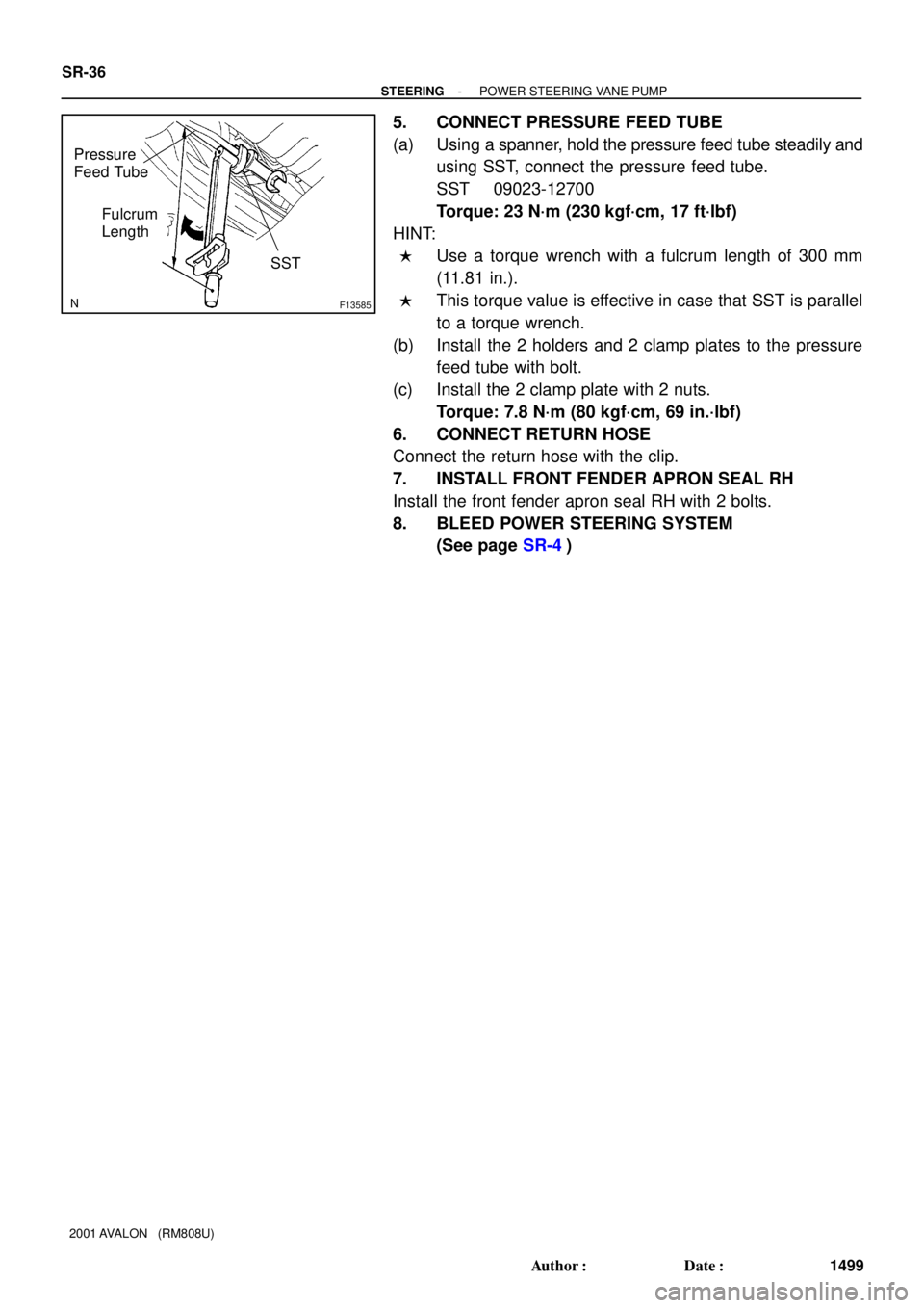
5. CONNECT PRESSURE FEED TUBE
(a) Using a spanner, hold the pressure feed tube steadily and
using SST, connect the pressure feed tube.
SST 09023-12700
Torque: 23 N´m (230 kgf´cm, 17 ft´lbf)
HINT:
�Use a torque wrench with a fulcrum length of 300 mm
(11.81 in.).
�This torque value is effective in case that SST is parallel
to a torque wrench.
(b) Install the 2 holders and 2 clamp plates to the pressure
feed tube with bolt.
(c) Install the 2 clamp plate with 2 nuts.
Torque: 7.8 N´m (80 kgf´cm, 69 in.´lbf)
6. CONNECT RETURN HOSE
Connect the return hose with the clip.
7. INSTALL FRONT FENDER APRON SEAL RH
Install the front fender apron seal RH with 2 bolts.
8. BLEED POWER STEERING SYSTEM
(See page SR-4)
Page 1810 of 1897

REASSEMBLY
NOTICE:
When using a vise, do not overtighten it.")
SR0ER-03
R13458
Inscribed Mark
R01149
Round End
R11292
- STEERINGPOWER STEERING VANE PUMP
SR-33
1496 Author�: Date�:
2001 AVALON (RM808U)
REASSEMBLY
NOTICE:
When using a vise, do not overtighten it.
1. COAT PARTS INDICATED BY ARROWS WITH POWER
STEERING FLUID (See page SR-25)
2. INSTALL 2 STRAIGHT PINS
Using a plastic hammer, tap in 2 new straight pins.
NOTICE:
Be careful not to damage the straight pins.
3. INSTALL VANE PUMP SHAFT
4. INSTALL CAM RING
Align the holes of the cam ring and 2 straight pins, and install
the cam ring with the inscribed mark facing outward.
5. INSTALL VANE PUMP ROTOR
(a) Install the vane pump rotor with the inscribed mark facing
outward.
(b) Install a new snap ring to the vane pump shaft.
6. INSTALL 10 VANE PLATES
Install the 10 vane plates with the round end facing outward.
7. INSTALL GASKET
Install a new gasket.
8. INSTALL SIDE PLATE
Align the holes of the side plate and 2 straight pins, and install
the side plate.
9. INSTALL WAVE WASHER
Install the wave washer so that its protrusions fit into the slots
in the side plate.
10. INSTALL REAR HOUSING
(a) Coat 2 new O-rings with power steering fluid and install
them to the rear housing.
(b) Install the rear housing with 4 bolts.
Torque: 17 N´m (170 kgf´cm, 12 ft´lbf)
Page 1811 of 1897

11. INSTALL SPRING, FLOW CONTROL VALVE AND
PRESSURE PORT UNION
(a) Install the spring.
(b) Install the f")
F08854
SST
SR-34
- STEERINGPOWER STEERING VANE PUMP
1497 Author�: Date�:
2001 AVALON (RM808U)
11. INSTALL SPRING, FLOW CONTROL VALVE AND
PRESSURE PORT UNION
(a) Install the spring.
(b) Install the flow control valve facing in the correct direction
(See page SR-25).
(c) Coat a new O-ring with power steering fluid and install it
to the pressure port union.
(d) Install the pressure port union.
Torque: 83 N´m (850 kgf´cm, 62 ft´lbf)
12. INSTALL SUCTION PORT UNION
(a) Coat a new O-ring with power steering fluid and install it
to the suction port union.
(b) Install the suction port union with bolt.
Torque: 13 N´m (130 kgf´cm, 9 ft´lbf)
13. INSTALL FRONT AND REAR BRACKETS
Install the front and rear brackets with 3 bolts and 2 nuts.
Torque: 43 N´m (440 kgf´cm, 32 ft´lbf)
14. INSTALL VANE PUMP PULLEY
(a) Install the vane pump pulley and nut to the vane pump
shaft.
(b) Using SST, stop the pulley rotating and torque the nut.
SST 09960-10010 (09962-01000, 09963-01000)
Torque: 44 N´m (450 kgf´cm, 33 ft´lbf)
15. MEASURE PS VANE PUMP ROTATING TORQUE
(See page SR-28)
Page 1812 of 1897

REMOVAL
1. REMOVE FRONT FENDER APRON SEAL RH
Remove the 2 bolts an")
SR0EO-06
F13584
Pressure Feed TubeSST
F08855
A
B
- STEERINGPOWER STEERING VANE PUMP
SR-27
1490 Author�: Date�:
2001 AVALON (RM808U)
REMOVAL
1. REMOVE FRONT FENDER APRON SEAL RH
Remove the 2 bolts and front fender apron seal RH.
2. DISCONNECT RETURN HOSE
Remove the clip and disconnect the return hose.
NOTICE:
Take care not to spill fluid on the drive belt.
3. DISCONNECT PRESSURE FEED TUBE
(a) Remove the 2 clamp plate set nuts.
(b) Remove the bolt, 2 clamp plates and 2 holders from the
pressure feed tube.
(c) Using a spanner, hold the pressure feed tube steadily and
using SST, disconnect the pressure feed tube.
SST 09023-12700
4. REMOVE DRIVE BELT
Loosen the 2 (A and B) bolts and drive belt.
5. REMOVE PS VANE PUMP ASSEMBLY WITH PRES-
SURE FEED TUBE
(a) Disconnect the connector from the oil pressure switch.
(b) Loosen the bolt A sufficiently so that pump assembly can
be removed.
HINT:
Bolt A cannot be removed.
(c) Remove the bolt B and PS vane pump assembly.
6. REMOVE OIL PRESSURE SWITCH
NOTICE:
Be careful not to drop the switch.
If the switch is dropped or strongly damaged, replace it with a
new one.
7. REMOVE PRESSURE FEED TUBE
(a) Remove the oil pressure switch from the union bolt.
(b) Remove the union bolt, gasket and pressure feed tube.
Page 1813 of 1897
SR0RU-02
R11290
Vinyl Tape
W03541
Press
SST
Oil Seal SR-32
- STEERINGPOWER STEERING VANE PUMP
1495 Author�: Date�:
2001 AVALON (RM808U)
REPLACEMENT
NOTICE:
When using a vise, do not overtighten it.
IF NECESSARY, REPLACE OIL SEAL
(a) Using a screwdriver with vinyl tape wound around its tip,
remove the oil seal.
NOTICE:
Be careful not to damage the front housing.
(b) Coat a new oil seal lip with power steering fluid.
(c) Using SST, press in the oil seal.
SST 09950-60010 (09951-00330),
09950-70010 (09951-07100)
NOTICE:
Make sure that the oil seal is installed facing in the correct
direction.
Page 1814 of 1897
SR0EB-02
- STEERINGSTEERING SYSTEM
SR-1
1464 Author�: Date�:
2001 AVALON (RM808U)
STEERING SYSTEM
PRECAUTION
�Care must be taken to replace parts properly because they could affect the performance of the
steering system and result in a driving hazard.
�The AVALON is equipped with SRS (Supplemental Restraint System) such as the driver airbag
and front passenger airbag. Failure to carry out service operation in the correct sequence could
cause the SRS to unexpectedly deploy during servicing, possibly leading to a serious accident.
Before servicing (including removal or installation of parts, inspection or replacement), be sure
to read the precautionary notices in the RS section.
Page 1815 of 1897
F08857
SR0EG-05
F08858
SR-8
- STEERINGSTEERING WHEEL
1471 Author�: Date�:
2001 AVALON (RM808U)
STEERING WHEEL
INSPECTION
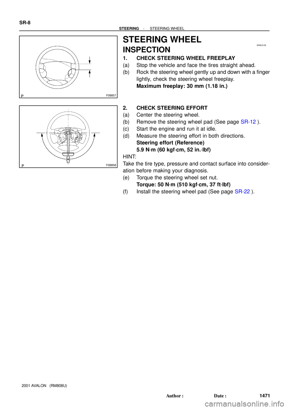
1. CHECK STEERING WHEEL FREEPLAY
(a) Stop the vehicle and face the tires straight ahead.
(b) Rock the steering wheel gently up and down with a finger
lightly, check the steering wheel freeplay.
Maximum freeplay: 30 mm (1.18 in.)
2. CHECK STEERING EFFORT
(a) Center the steering wheel.
(b) Remove the steering wheel pad (See page SR-12).
(c) Start the engine and run it at idle.
(d) Measure the steering effort in both directions.
Steering effort (Reference)
5.9 N´m (60 kgf´cm, 52 in.´lbf)
HINT:
Take the tire type, pressure and contact surface into consider-
ation before making your diagnosis.
(e) Torque the steering wheel set nut.
Torque: 50 N´m (510 kgf´cm, 37 ft´lbf)
(f) Install the steering wheel pad (See page SR-22).