Page 1793 of 1897

9. INSTALL OIL SEAL
(a) Coat a new oil seal lip with power steering fl")
W03562
Press
SST
Oil Seal
R11648
SST
R11659
Punch
- STEERINGPOWER STEERING GEAR
SR-51
1514 Author�: Date�:
2001 AVALON (RM808U)
9. INSTALL OIL SEAL
(a) Coat a new oil seal lip with power steering fluid.
(b) Using SST, press in the oil seal.
SST 09612-2201 1
NOTICE:
Make sure that the oil seal is installed facing in the correct
direction.
10. INSTALL CONTROL VALVE HOUSING WITH CON-
TROL VALVE ASSEMBLY
(a) Place a new gasket on the rack housing.
(b) Align the matchmarks on the control valve housing and
rack housing.
(c) Install the 2 bolts.
Torque: 18 N´m (180 kgf´cm, 13 ft´lbf)
11. INSTALL SELF-LOCKING NUT
Using SST, stop the control valve shaft rotating and install a new
self-locking nut.
SST 09616-0001 1
Torque: 25 N´m (250 kgf´cm, 18 ft´lbf)
12. INSTALL DUST SEAL
13. INSTALL RACK HOUSING CAP
(a) Apply sealant to 2 or 3 threads of the rack housing cap.
Sealant:
Part No.08833-00080, THREE BOND 1344,
LOCTITE 242 or equivalent
(b) Install the rack housing cap.
Torque: 59 N´m (600 kgf´cm, 43 ft´lbf)
(c) Using a punch and hammer, stake the 2 parts of the rack
housing cap.
14. INSTALL RACK GUIDE SUB- ASSEMBLY, RACK
GUIDE SPRING AND RACK GUIDE SPRING CAP
(a) Install the rack guide sub- assembly and rack guide
spring.
(b) Apply sealant to 2 or 3 threads of the rack guide spring
cap.
Sealant:
Part No.08833-00080, THREE BOND 1344,
LOCTITE 242 or equivalent
(c) Temporarily install the rack guide spring cap.
Page 1797 of 1897
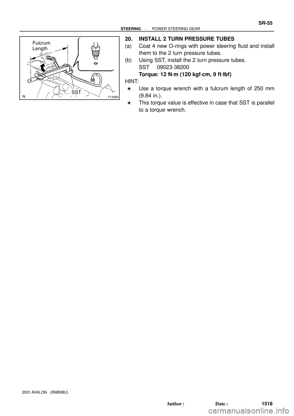
F13588SST
Fulcrum
Length
- STEERINGPOWER STEERING GEAR
SR-55
1518 Author�: Date�:
2001 AVALON (RM808U)
20. INSTALL 2 TURN PRESSURE TUBES
(a) Coat 4 new O-rings with power steering fluid and install
them to the 2 turn pressure tubes.
(b) Using SST, install the 2 turn pressure tubes.
SST 09023-38200
Torque: 12 N´m (120 kgf´cm, 9 ft´lbf)
HINT:
�Use a torque wrench with a fulcrum length of 250 mm
(9.84 in.).
�This torque value is effective in case that SST is parallel
to a torque wrench.
Page 1799 of 1897

SR0RX-02
F01792
Press
SST
Oil Seal
Bearing
W03560
Press
SST
Oil SealSST
F03877
PressSST
SST Bearing
F01794
Brass Bar
Bearing
F01795
Press
SST
Bearing
SR-46
- STEERINGPOWER STEERING GEAR
1509 Author�: Date�:
2001 AVALON (RM808U)
REPLACEMENT
NOTICE:
When using a vise, do not over tighten it.
1. IF NECESSARY, REPLACE OIL SEAL AND BEARING
(a) Using SST, press out the oil seal and bearing from the
control valve housing.
SST 09950-60010 (09951-00250),
09950-70010 (09951-07200)
(b) Coat a new oil seal lip with power steering fluid.
(c) Using SST, press in the oil seal.
SST 09950-60010 (09951-00180, 09951-00320,
09952-06010), 09950-70010 (09951-07200)
NOTICE:
Make sure that the oil seal is installed facing in the correct
direction.
(d) Coat a new bearing with molybdenum disulfide lithium
base grease.
(e) Using SST, press in the bearing.
SST 09950-60010 (09951-00180, 09951-00340,
09952-06010), 09950-70010 (09951-07200)
2. IF NECESSARY, REPLACE 2 BEARINGS
(a) Using a brass bar and hammer, tap out the bearing from
the rack housing.
(b) Using SST, press out the bearing from the rack housing.
SST 09950-60010 (09951-00260),
09950-70010 (09951-07200)
Page 1800 of 1897
")
F03878
PressSST
SST
Bearing
F01797
Press
SST
Bearing
F01798SST
BushingOil
Seal
SST
F03863
Press
Oil Seal
SST
SST
R10955
- STEERINGPOWER STEERING GEAR
SR-47
1510 Author�: Date�:
2001 AVALON (RM808U)
(c) Coat a new bearing with molybdenum disulfide lithium
base grease.
(d) Using SST, press in the bearing.
SST 09950-60010 (09951-00250, 09951-00310,
09952-06010), 09950-70010 (09951-07200)
(e) Coat a new bearing with molybdenum disulfide lithium
base grease.
(f) Using SST, press in the bearing.
SST 09950-60010 (09951-00320),
09950-70010 (09951-07200)
3. IF NECESSARY, REPLACE OIL SEAL
(a) Using SST, remove the oil seal from the bushing.
SST 09527-2001 1, 09612-24014 (09613-22011)
NOTICE:
Be careful not to damage the bushing.
(b) Coat a new oil seal lip with power steering fluid.
(c) Using SST, press in the oil seal.
SST 09950-60010 (09951-00240, 09951-00400,
09952-06010)
NOTICE:
Make sure that the oil seal is installed facing in the correct
direction.
4. IF NECESSARY, REPLACE TEFLON RING AND O-
RING
(a) Using a screwdriver, remove the teflon ring and O-ring
from the steering rack.
NOTICE:
Be careful not to damage the groove for the teflon ring.
(b) Coat a new O-ring with power steering fluid and install it.
Page 1801 of 1897

(c) Expand a new teflon ring with your fingers.
NOTICE:
Be care")
R06172
N00401
R11572
Teflon Ring
R11573
SST
Teflon Ring SR-48
- STEERINGPOWER STEERING GEAR
1511 Author�: Date�:
2001 AVALON (RM808U)
(c) Expand a new teflon ring with your fingers.
NOTICE:
Be careful not to over expand the ring.
(d) Coat the teflon ring with power steering fluid.
(e) Install the teflon ring to the steering rack, and settle it
down with your fingers.
5. IF NECESSARY, REPLACE 4 TEFLON RINGS
(a) Using a screwdriver, remove the 4 teflon rings from the
control valve assembly.
NOTICE:
Be careful not to damage the grooves for the teflon ring.
(b) Expand 4 new teflon rings with your fingers.
NOTICE:
Be careful not to over expand the teflon ring.
(c) Coat the teflon rings with power steering fluid.
(d) Install the teflon rings to the control valve assembly, and
settle them down with your fingers.
(e) Carefully slide the tapered end of SST over the teflon
rings until the teflon rings fit to the control valve assembly.
SST 09631-20081
NOTICE:
Be careful not to damage the teflon rings.
Page 1803 of 1897
F08852
Pressure Port Union
� O-Ring
Flow Control Valve
Suction Port Union
SpringRear Housing
Rear
Bracket
Front Housing
Front Bracket
Vane Pump Shaft
Vane Pump PulleyVane Pump
Rotor
� Straight Pin
Wave Washer � O-Ring� O-Ring
� Gasket
Side Plate
Cam Ring
Vane Platex 10
� Oil Seal�
� Snap Ring
� Non-reusable part
Power steering fluid
83 (850, 62)
13 (130, 9)
43 (440, 32)
43 (440, 32)
17 (170, 12)
17 (170, 12)
44 (450, 33)
N´m (kgf´cm, ft´lbf): Specified torque
SR-26
- STEERINGPOWER STEERING VANE PUMP
1489 Author�: Date�:
2001 AVALON (RM808U)
Page 1806 of 1897

If it is more than the maximum, replace the")
R13897Inscribed Mark
R11288
R07591
Compressed Air
R11563Inscribed Mark
SR-30
- STEERINGPOWER STEERING VANE PUMP
1493 Author�: Date�:
2001 AVALON (RM808U)
If it is more than the maximum, replace the vane plate and/or
vane pump rotor with the one having the same mark stamped
on the cam ring.
Inscribed mark: 1, 2, 3, 4 or None
HINT:
There are 5 vane plate lengths with the following vane pump ro-
tor and cam ring marks:
Vane pump rotor and cam
ring markVane plate part
numberVane plate length
mm (in.)
None44345-2601014.999-15.001
(0.59051-0.59059)
144345-2602014.997-14.999
(0.59043-0.59051)
244345-2603014.995-14.997
(0.59035-0.59043)
344345-2604014.993-14.995
(0.59027-0.59035)
444345-2605014.991-14.993
(0.59020-0.59027)
3. INSPECT FLOW CONTROL VALVE
(a) Coat the flow control valve with power steering fluid and
check that it falls smoothly into the flow control valve hole
by its own weight.
(b) Check the flow control valve for leakage. Close one of the
holes and apply 392 - 490 kPa (4 - 5 kgf/cm
2, 57 - 71 psi)
of compressed air into the opposite side hole, and confirm
that air does not come out from the end holes.
If necessary, replace the flow control valve with the one having
the same letter as inscribed on the front housing.
Inscribed Mark: A, B, C, D, E or F
Page 1810 of 1897

REASSEMBLY
NOTICE:
When using a vise, do not overtighten it.")
SR0ER-03
R13458
Inscribed Mark
R01149
Round End
R11292
- STEERINGPOWER STEERING VANE PUMP
SR-33
1496 Author�: Date�:
2001 AVALON (RM808U)
REASSEMBLY
NOTICE:
When using a vise, do not overtighten it.
1. COAT PARTS INDICATED BY ARROWS WITH POWER
STEERING FLUID (See page SR-25)
2. INSTALL 2 STRAIGHT PINS
Using a plastic hammer, tap in 2 new straight pins.
NOTICE:
Be careful not to damage the straight pins.
3. INSTALL VANE PUMP SHAFT
4. INSTALL CAM RING
Align the holes of the cam ring and 2 straight pins, and install
the cam ring with the inscribed mark facing outward.
5. INSTALL VANE PUMP ROTOR
(a) Install the vane pump rotor with the inscribed mark facing
outward.
(b) Install a new snap ring to the vane pump shaft.
6. INSTALL 10 VANE PLATES
Install the 10 vane plates with the round end facing outward.
7. INSTALL GASKET
Install a new gasket.
8. INSTALL SIDE PLATE
Align the holes of the side plate and 2 straight pins, and install
the side plate.
9. INSTALL WAVE WASHER
Install the wave washer so that its protrusions fit into the slots
in the side plate.
10. INSTALL REAR HOUSING
(a) Coat 2 new O-rings with power steering fluid and install
them to the rear housing.
(b) Install the rear housing with 4 bolts.
Torque: 17 N´m (170 kgf´cm, 12 ft´lbf)