Page 848 of 1897

I13617
Cruise Control ECU
4 3
3
W-B8 Stop Light Switch
4Cruise Control Actuator
13
II1
IJJ9
J/CL
9P-B P-B G-B GNDL
AC4
S4
C15
W-B II1
- DIAGNOSTICSCRUISE CONTROL SYSTEM
DI-563
719 Author�: Date�:
2001 AVALON (RM808U)
DTC 12 Actuator Magnetic Clutch Circuit
CIRCUIT DESCRIPTION
This circuit turns on the magnetic clutch inside the actuator during cruise control operation according to the
signal from the ECU. If a malfunction occurs in the actuator or speed sensor, etc. during cruise control opera-
tion, the rotor shaft between the motor and control plate is released.
When the brake pedal is depressed, the stop light switch turns on, supplying electrical power to the stop light.
Power supply to the magnetic clutch is mechanically cut and the magnetic clutch is turned OFF.
When driving downhill, if the vehicle speed exceeds the set speed by 15 km/h (9 mph), the ECU turns the
safety magnet clutch OFF. If the vehicle speed later drops to within 10 km/h (6 mph), cruise control at the
set speed is resumed.
DTC No.Detection ItemTrouble Area
12Short in actuator magnetic clutch circuit.
Open (0.8 sec.) in actuator magnetic clutch circuit.
�STOP Fuse
�Stop light switch
�Actuator magnetic clutch
�Harness or connector between cruise control ECU and
actuator magnetic clutch, actuator magnetic clutch and body
ground
�Cruise control ECU
WIRING DIAGRAM
DI08N-15
Page 851 of 1897
I00055
4
3(+)
(-)
DI-566
- DIAGNOSTICSCRUISE CONTROL SYSTEM
722 Author�: Date�:
2001 AVALON (RM808U)
DTC 14 Actuator Mechanical Malfunction
CIRCUIT DESCRIPTION
The circuit detects the rotation position of the actuator control plate and sends a signal to the ECU.
DTC No.Detection ItemTrouble Area
14Cruise control actuator mechanical malfunction.
�Actuator lock: (motor, arm)
�Actuator motor
�Cruise control ECU
WIRING DIAGRAM
See page DI-563.
INSPECTION PROCEDURE
1 Check cruise control actuator arm locking operation
PREPARATION:
(a) Turn ignition switch OFF.
(b) Disconnect the actuator connector.
CHECK:
(a) Connect the positive (+) lead from the battery to the termi-
nal 3 of actuator and the negative (-) lead to terminal 4.
NOTICE:
Do not connect the high tension cables to the wrong bat-
tery terminal. The cruise control actuator will be damaged.
(b) Move the control plate by hand.
OK:
Control plate doesn't move.
NG Replace cruise control actuator.
OK
DI08O-14
Page 853 of 1897

I00292
Vehicle Speed Sensor
ECUCombination Meter
Cruise Control ECU
4 pulses/
1 rotation
of rotor shaft4 pulses/
1 rotation
of rotor shaft
I13616
Cruise Control ECU
12 Combination Meter
3C10
V-W V-W
Y-R BR
to
ABS ECU3F1
M322
M3 M37
BR IJ1 11
EBM3
to ECU-IG Fuse 18
SPD
C15
J/B No. 3
1 DI-568
- DIAGNOSTICSCRUISE CONTROL SYSTEM
724 Author�: Date�:
2001 AVALON (RM808U)
DTC 21 Open in Vehicle Speed Sensor Circuit
CIRCUIT DESCRIPTION
The signal from the vehicle speed sensor circuit is sent to cruise control ECU as vehicle speed signal.
The rotor shaft is driven by the gear of the transmission.
For each rotation of the shaft, the vehicle speed sensor sends a 4-pulse signal through the combination
meter to the cruise control ECU (See the following installation).
This signal is converted inside the combination meter and sent as a 4-pulse signal to the cruise control ECU.
The ECU calculates the vehicle speed from this pulse frequency.
DTC No.Detection ItemTrouble Area
21Speed signal is not input to the cruise control ECU while cruise
control is set.
�Combination meter
�Harness or connector between cruise control ECU and com-
bination meter, combination meter and vehicle speed sensor
�Vehicle speed sensor
�Cruise control ECU
WIRING DIAGRAM
DI08P-18
Page 856 of 1897
- DIAGNOSTICSCRUISE CONTROL SYSTEM
DI-571
727 Author�: Date�:
2001 AVALON (RM808U)
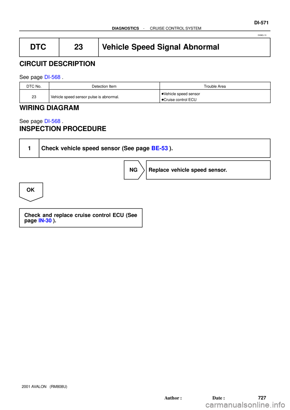
DTC 23 Vehicle Speed Signal Abnormal
CIRCUIT DESCRIPTION
See page DI-568.
DTC No.Detection ItemTrouble Area
23Vehicle speed sensor pulse is abnormal.�Vehicle speed sensor
�Cruise control ECU
WIRING DIAGRAM
See page DI-568.
INSPECTION PROCEDURE
1 Check vehicle speed sensor (See page BE-53).
NG Replace vehicle speed sensor.
OK
Check and replace cruise control ECU (See
page IN-30).
DI08Q-13
Page 857 of 1897
I13615
Cruise Control ECU
W-L
W-BW-B
MAINCANCEL
COAST/
SETRES/
ACC 41
10 3A
53
W
IG
J5
J/C 20
73A
A
A
W-BCAN
CCS Cruise Control Switch
C12
C15
J/B
No. 3 DI-572
- DIAGNOSTICSCRUISE CONTROL SYSTEM
728 Author�: Date�:
2001 AVALON (RM808U)
DTC 32 Control Switch Circuit (Cruise Control
Switch)
CIRCUIT DESCRIPTION
This circuit carries the SET/COAST, RESUME/ACCEL and CANCEL signals (each voltage) to the ECU.
DTC No.Detection ItemTrouble Area
32Short in control switch circuit.
�Cruise control switch
�Harness or connector between cruise control ECU and
cruise control switch, cruise control switch and body ground
�Cruise control ECU
WIRING DIAGRAM
DI08R-16
Page 860 of 1897
I13614
IDL 13
IDLOE725 ECMCruise Control ECU
Y
C15
- DIAGNOSTICSCRUISE CONTROL SYSTEM
DI-575
731 Author�: Date�:
2001 AVALON (RM808U)
DTC 51 Idle Signal Circuit
CIRCUIT DESCRIPTION
When the idle switch is turned ON, a signal is sent to the ECU. The ECU uses this signal to correct the dis-
crepancy between the throttle valve position and the actuator position sensor value to enable accurate
cruise control at the set speed. If the idle switch is malfunctioning, problem symptoms also occur in the en-
gine, so also inspect the engine.
DTC No.Detection ItemTrouble Area
51Short in idle signal circuit.
�Harness or connector between ECM and throttle position
sensor
�Throttle position sensor
�Harness or connector between cruise control ECU and ECM
�Cruise control ECU
WIRING DIAGRAM
DI6L6-01
Page 864 of 1897
AB0119
I00145
I00177
ON
CAN
(-) (+)
DI-590
- DIAGNOSTICSCRUISE CONTROL SYSTEM
746 Author�: Date�:
2001 AVALON (RM808U)
Cancel Switch Circuit (Cruise Control Switch)
CIRCUIT DESCRIPTION
When the cruise control cancel switch is turned ON, the cruise control does not operate.
WIRING DIAGRAM
See page DI-572.
INSPECTION PROCEDURE
1 Check voltage between terminal CAN of cruise control ECU connector and body
ground.
PREPARATION:
(a) Remove the ECU with connector still connected.
(b) Turn ignition switch ON.
CHECK:
Measure voltage between terminal CAN of cruise control ECU
connector when main switch is held ON and OFF.
OK:
Main switchVoltage
OFF10 - 14 V
ONBelow 0.5 V
OK Proceed to next circuit inspection shown on
problem symptom table (See page DI-560).
NG
DI6L8-01
Page 866 of 1897
I13610
Cruise Control ECU
4
PI
R-B
W-B10
1D
IF17W-R
4 IG1 AM1Ignition Switch 2
W
AM1 GAUGE NO. 1
2 1
5
B-L1
ALTFL Block
1 B
FL MAIN
BatteryF8 2G1
F6 F10
1
1
2H
B 5
W-LW-L 1
43 3
1B1
1G
4
1C IG1 RERAY 4
4D13
4F4
M7 M64
4H17
4A17
GR-R
R-BGR-R Cruise Control
Indicator Light
(in Multi Display)
IG
C15
I15
2J/B No. 4 J/B No. 4
Driver Side J/B
Engine Room R/B No. 5
Engine Room J/B DI-592
- DIAGNOSTICSCRUISE CONTROL SYSTEM
748 Author�: Date�:
2001 AVALON (RM808U)
CRUISE MAIN Indicator Light Circuit
CIRCUIT DESCRIPTION
When the cruise control main switch is turned ON, CRUISE MAIN indicator light lights up.
WIRING DIAGRAM
DI090-28