2001 NISSAN X-TRAIL Obd
[x] Cancel search: ObdPage 14 of 3833
GI-12
HOW TO USE THIS MANUAL
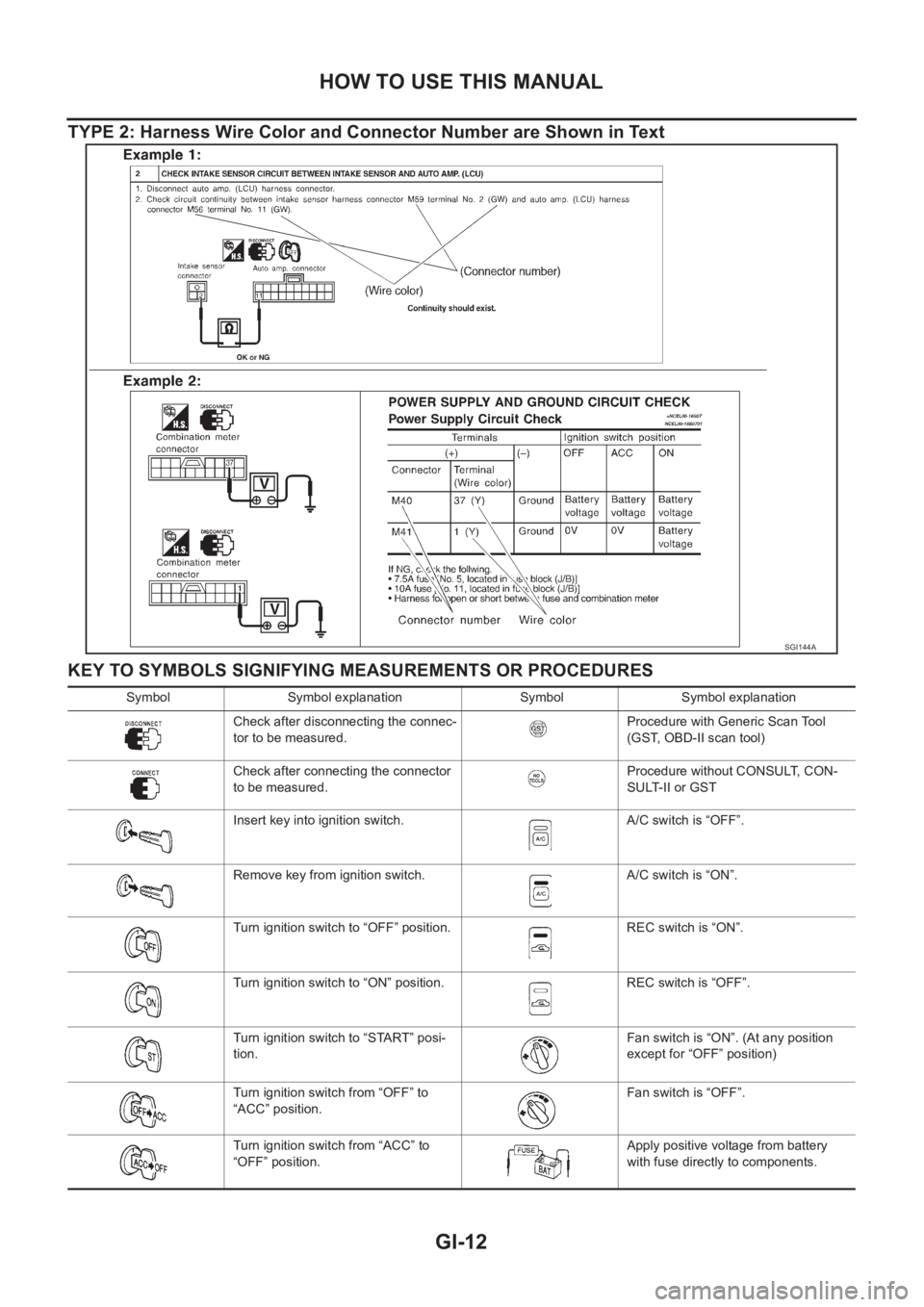
TYPE 2: Harness Wire Color and Connector Number are Shown in Text
KEY TO SYMBOLS SIGNIFYING MEASUREMENTS OR PROCEDURES
SGI144A
Symbol Symbol explanation Symbol Symbol explanation
Check after disconnecting the connec-
tor to be measured.Procedure with Generic Scan Tool
(GST, OBD-II scan tool)
Check after connecting the connector
to be measured.Procedure without CONSULT, CON-
SULT-II or GST
Insert key into ignition switch. A/C switch is “OFF”.
Remove key from ignition switch. A/C switch is “ON”.
Turn ignition switch to “OFF” position. REC switch is “ON”.
Turn ignition switch to “ON” position. REC switch is “OFF”.
Turn ignition switch to “START” posi-
tion.Fan switch is “ON”. (At any position
except for “OFF” position)
Turn ignition switch from “OFF” to
“ACC” position.Fan switch is “OFF”.
Turn ignition switch from “ACC” to
“OFF” position.Apply positive voltage from battery
with fuse directly to components.
Page 16 of 3833
GI-14
HOW TO USE THIS MANUAL
How to Read Wiring Diagrams
EAS000G4
CONNECTOR SYMBOLS
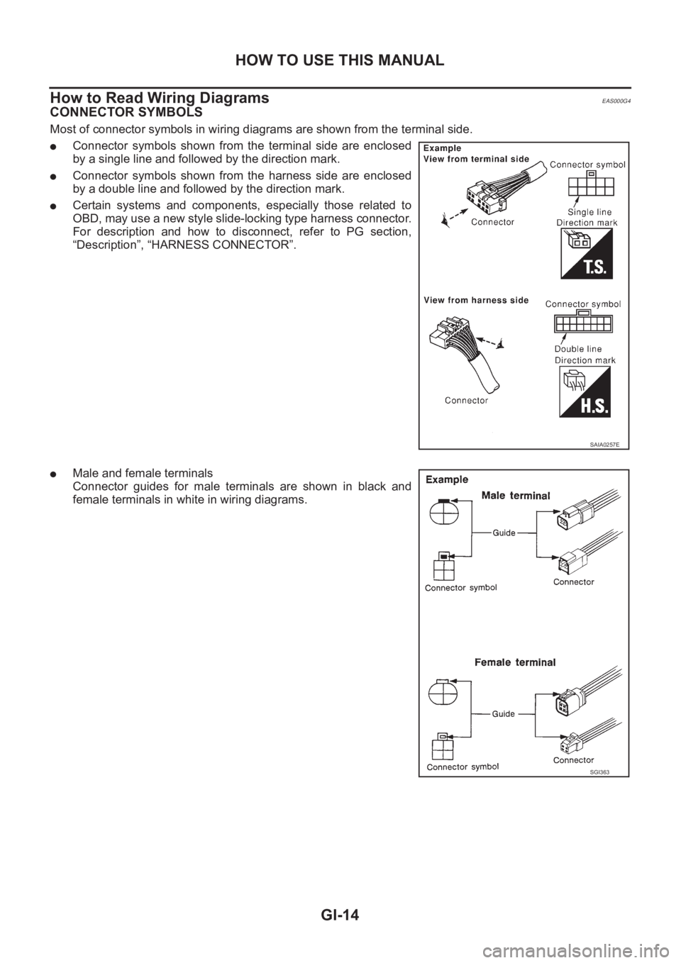
Most of connector symbols in wiring diagrams are shown from the terminal side.
●Connector symbols shown from the terminal side are enclosed
by a single line and followed by the direction mark.
●Connector symbols shown from the harness side are enclosed
by a double line and followed by the direction mark.
●Certain systems and components, especially those related to
OBD, may use a new style slide-locking type harness connector.
For description and how to disconnect, refer to PG section,
“Description”, “HARNESS CONNECTOR”.
●Male and female terminals
Connector guides for male terminals are shown in black and
female terminals in white in wiring diagrams.
SAIA0257E
SGI363
Page 49 of 3833

TERMINOLOGY
GI-47
C
D
E
F
G
H
I
J
K
L
MB
GI
Nonvolatile random access memory NVRAM ***
On board diagnostic system OBD system Self-diagnosis
Open loop OL Open loop
Oxidation catalyst OC Catalyst
Oxidation catalytic converter system OC system ***
Oxygen sensor O2S Exhaust gas sensor
Park position switch *** Park switch
Park/neutral position switch PNP switchPark/neutral switch
Inhibitor switch
Neutral position switch
Periodic trap oxidizer system PTOX system ***
Positive crankcase ventilation PCV Positive crankcase ventilation
Positive crankcase ventilation valve PCV valve PCV valve
Powertrain control module PCM ***
Programmable read only memory PROM ***
Pulsed secondary air injection control sole-
noid valvePAIRC solenoid valve AIV control solenoid valve
Pulsed secondary air injection system PAIR system Air induction valve (AIV) control
Pulsed secondary air injection valve PAIR valve Air induction valve
Random access memory RAM ***
Read only memory ROM ***
Scan tool ST ***
Secondary air injection pump AIR pump ***
Secondary air injection system AIR system ***
Sequential multiport fuel injection system SFI system Sequential fuel injection
Service reminder indicator SRI ***
Simultaneous multiport fuel injection sys-
tem*** Simultaneous fuel injection
Smoke puff limiter system SPL system ***
Supercharger SC ***
Supercharger bypass SCB ***
System readiness test SRT ***
Thermal vacuum valve TVV Thermal vacuum valve
Three way catalyst TWC Catalyst
Three way catalytic converter system TWC system ***
Three way + oxidation catalyst TWC + OC Catalyst
Three way + oxidation catalytic converter
systemTWC + OC system ***
Throttle body TBThrottle chamber
SPI body
Throttle body fuel injection system TBI system Fuel injection control
Throttle position TP Throttle position
Throttle position sensor TPS Throttle sensor
Throttle position switch TP switch Throttle switch
Torque converter clutch solenoid valve TCC solenoid valveLock-up cancel solenoid
Lock-up solenoid NEW TERMNEW ACRONYM /
ABBREVIATIONOLD TERM
Page 67 of 3833
![NISSAN X-TRAIL 2001 Service Repair Manual INTAKE MANIFOLD
EM-17
[QR]
C
D
E
F
G
H
I
J
K
L
MA
EM
QR25DE
REMOVAL
WARNING:
To avoid the danger of being scalded, never drain the coolant when the engine is hot.
1. Disconnect mass air flow sensor ha](/manual-img/5/57405/w960_57405-66.png "NISSAN X-TRAIL 2001 Service Repair Manual INTAKE MANIFOLD
EM-17
[QR]
C
D
E
F
G
H
I
J
K
L
MA
EM
QR25DE
REMOVAL
WARNING:
To avoid the danger of being scalded, never drain the coolant when the engine is hot.
1. Disconnect mass air flow sensor ha")
INTAKE MANIFOLD
EM-17
[QR]
C
D
E
F
G
H
I
J
K
L
MA
EM
QR25DE
REMOVAL
WARNING:
To avoid the danger of being scalded, never drain the coolant when the engine is hot.
1. Disconnect mass air flow sensor harness connector from mass air flow sensor and clamp.
2. Release fuel pressure. Refer to EC-775, "
FUEL PRESSURE RELEASE" [QR20DE (WITH EURO-OBD)],
EC-1139, "
FUEL PRESSURE RELEASE" [QR20DE (WITHOUT EURO-OBD)], EC-42, "FUEL PRES-
SURE RELEASE" [QR25DE (WITH EURO-OBD)] or EC-452, "FUEL PRESSURE RELEASE" [QR25DE
(WITHOUT EURO-OBD)].
3. Remove air cleaner case and air duct assembly. Refer to EM-14, "
AIR CLEANER AND AIR DUCT" .
4. Drain coolant when engine is cooled. Refer to CO-9, "
DRAINING ENGINE COOLANT" .
SBIA0229E
1. Bracket 2. PCV hose 3. Intake manifold collector
4. Gasket 5. Electric throttle control actuator 6. Intake manifold support
7.EVAP canister purge volume control
solenoid valve8. Vacuum hose 9. Intake manifold
10. Vacuum reservoir tank 11. VIAS control solenoid valve
Page 73 of 3833
![NISSAN X-TRAIL 2001 Service Repair Manual INTAKE MANIFOLD
EM-23
[QR]
C
D
E
F
G
H
I
J
K
L
MA
EM
●Perform procedures for “Throttle Valve Closed Position Learning” after finishing repairs. Refer to EC-
772, "Throttle Valv](/manual-img/5/57405/w960_57405-72.png "NISSAN X-TRAIL 2001 Service Repair Manual INTAKE MANIFOLD
EM-23
[QR]
C
D
E
F
G
H
I
J
K
L
MA
EM
●Perform procedures for “Throttle Valve Closed Position Learning” after finishing repairs. Refer to EC-
772, \"Throttle Valv")
INTAKE MANIFOLD
EM-23
[QR]
C
D
E
F
G
H
I
J
K
L
MA
EM
●Perform procedures for “Throttle Valve Closed Position Learning” after finishing repairs. Refer to EC-
772, "Throttle Valve Closed Position Learning" [QR20DE (WITH EURO-OBD)], EC-1136, "Throttle
Valve Closed Position Learning" [QR20DE (WITHOUT EURO-OBD)], EC-39, "Throttle Valve Closed
Position Learning" [QR25DE (WITH EURO-OBD)] or EC-449, "Throttle Valve Closed Position Learn-
ing" [QR25DE (WITHOUT EURO-OBD)].
●If electric throttle control actuator is replaced, perform procedures for “Idle Air Volume Learning” after
finishing repairs. Refer to EC-772, "
Idle Air Volume Learning" [QR20DE (WITH EURO-OBD)], EC-
11 3 7 , "Idle Air Volume Learning" [QR20DE WITHOUT EURO-OBD)], EC-39, "Idle Air Volume Learn-
ing" [QR25DE (WITH EURO-OBD)] or EC-450, "Idle Air Volume Learning" [QR25DE (WITHOUT
EURO-OBD)].
Page 83 of 3833
![NISSAN X-TRAIL 2001 Service Repair Manual FUEL INJECTOR AND FUEL TUBE
EM-33
[QR]
C
D
E
F
G
H
I
J
K
L
MA
EM
●Do not remove or disassembly parts unless instructed as shown in the figure.
REMOVAL
1. Release fuel pressure. Refer to EC-775, "](/manual-img/5/57405/w960_57405-82.png "NISSAN X-TRAIL 2001 Service Repair Manual FUEL INJECTOR AND FUEL TUBE
EM-33
[QR]
C
D
E
F
G
H
I
J
K
L
MA
EM
●Do not remove or disassembly parts unless instructed as shown in the figure.
REMOVAL
1. Release fuel pressure. Refer to EC-775, \"")
FUEL INJECTOR AND FUEL TUBE
EM-33
[QR]
C
D
E
F
G
H
I
J
K
L
MA
EM
●Do not remove or disassembly parts unless instructed as shown in the figure.
REMOVAL
1. Release fuel pressure. Refer to EC-775, "FUEL PRESSURE RELEASE" [QR20DE (WITH EURO-OBD)],
EC-1139, "
FUEL PRESSURE RELEASE" [QR20DE (WITHOUT EURO-OBD)], EC-42, "FUEL PRES-
SURE RELEASE" [QR25DE (WITH EURO-OBD)] or EC-452, "FUEL PRESSURE RELEASE" [QR25DE
(WITHOUT EURO-OBD)].
2. Remove air duct, air cleaner case (upper) assembly.
3. Disconnect fuel hose quick connector at fuel tube side.
●Regarding how to disconnect and connect quick connector, Refer to EM-16, "INTAKE MANIFOLD" .
CAUTION:
●Prepare a container of cloth for spilled fuel.
●This operation should be performed, in a place where free from fire.
●While hoses are disconnected seal their openings with vinyl bag or similar material to prevent
foreign material from entering them.
4. Remove intake manifold collector. Refer to EM-16, "
INTAKE MANIFOLD" .
5. Disconnect sub-harness for injector at engine front side, and remove it from bracket.
6. Loosen mounting bolts in the reverse order in the figure, and
remove fuel tube and fuel injector assembly.
7. Remove fuel tube and fuel injector assembly.
●Release clip and remove it.
●Pull fuel injector straight out of fuel tube.
●Be careful not to damage nozzle part.
●Avoid any impact such as a dropping.
●Do not disassemble or adjust it.
INSTALLATION
1. Install O-rings to fuel injector paying attention to the items below.
●Lubricate O-rings by smearing new engine oil.
●Be careful not to scratch it with a tool or fingernails dur-
ing installation. Also be careful not to twist or stretch O-
ring. If O-ring was stretched while it is attached, do no
insert it into fuel tube immediately.
2. Install fuel injector to fuel tube with the following procedure.
●Insert clip into clip mounting groove on fuel injector.
●Insert clip so that projection A of fuel injector matches notch A
of the clip.
●Do not reuse clip. Replace it with a new one.
●Be careful to keep clip from interfering with O-ring. If interfer-
ence occurs, replace O-ring.
3. Insert fuel injector into fuel tube with clip attached.
●Insert it while matching it to the axial center.
●Insert fuel injector so that projection B of fuel injector matches
notch B of the clip.
●Make sure that fuel tube flange is securely fixed in flange fixing groove on clip.
●Make sure that installation is complete by checking that fuel injector does not rotate or come off.
4. Install fuel tube assembly with the following procedure.
a. Insert the tip of each fuel injector into intake manifold.
KBIA0239E
O-ring color
Fuel tube side (Upper side) : Black
Intake manifold side (Lower side) : Green
SBIA0439E
Page 96 of 3833
![NISSAN X-TRAIL 2001 Service Repair Manual EM-46
[QR]
CAMSHAFT
CAMSHAFT
PFP:13001
Removal and InstallationEBS00LS2
CAUTION:
Apply new engine oil to parts marked in illustration before installation.
REMOVAL
The following procedure describes rem](/manual-img/5/57405/w960_57405-95.png "NISSAN X-TRAIL 2001 Service Repair Manual EM-46
[QR]
CAMSHAFT
CAMSHAFT
PFP:13001
Removal and InstallationEBS00LS2
CAUTION:
Apply new engine oil to parts marked in illustration before installation.
REMOVAL
The following procedure describes rem")
EM-46
[QR]
CAMSHAFT
CAMSHAFT
PFP:13001
Removal and InstallationEBS00LS2
CAUTION:
Apply new engine oil to parts marked in illustration before installation.
REMOVAL
The following procedure describes removing and installing camshaft without removing front cover. If the front
cover is removed or installed, removal of No. 1 camshaft bracket is easier before step 8. Installation is easier
after step 3. Regarding removal and installation of front cover, refer to EM-37, "
TIMING CHAIN" .
1. Release fuel pressure. Refer to EC-775, "
FUEL PRESSURE RELEASE" [QR20DE (WITH EURO-OBD)],
EC-1139, "
FUEL PRESSURE RELEASE" [QR20DE (WITHOUT EURO-OBD)], EC-42, "FUEL PRES-
SURE RELEASE" [QR25DE (WITH EURO-OBD)] or EC-452, "FUEL PRESSURE RELEASE" [QR25DE
(WITHOUT EURO-OBD)].
2. Remove parts listed below.
●Ignition coil; Refer to EM-29, "IGNITION COIL" .
●Rocker cover; Refer to EM-35, "ROCKER COVER" .
3. Remove power steering reservoir tank.
KBIA0244E
1. Camshaft bracket 2. Washer 3. Front cover
4. Chain guide 5. Chain tensioner 6. O-ring
7. Spring 8. Chain tensioner plunger 9.Intake valve timing control solenoid
valve
10. Intake valve timing control cover 11. Camshaft sprocket (EXH) 12. Camshaft sprocket (INT)
13. Valve lifter 14. Camshaft (EXH) 15. Camshaft (INT)
16. Camshaft position sensor (PHASE)
Page 109 of 3833
![NISSAN X-TRAIL 2001 Service Repair Manual CYLINDER HEAD
EM-59
[QR]
C
D
E
F
G
H
I
J
K
L
MA
EM
CYLINDER HEADPFP:11041
On-Vehicle ServiceEBS00KNP
CHECKING COMPRESSION PRESSURE
1. Warm up engine thoroughly. Then, stop it.
2. Release fuel pressure](/manual-img/5/57405/w960_57405-108.png "NISSAN X-TRAIL 2001 Service Repair Manual CYLINDER HEAD
EM-59
[QR]
C
D
E
F
G
H
I
J
K
L
MA
EM
CYLINDER HEADPFP:11041
On-Vehicle ServiceEBS00KNP
CHECKING COMPRESSION PRESSURE
1. Warm up engine thoroughly. Then, stop it.
2. Release fuel pressure")
CYLINDER HEAD
EM-59
[QR]
C
D
E
F
G
H
I
J
K
L
MA
EM
CYLINDER HEADPFP:11041
On-Vehicle ServiceEBS00KNP
CHECKING COMPRESSION PRESSURE
1. Warm up engine thoroughly. Then, stop it.
2. Release fuel pressure. Refer to EC-775, "
FUEL PRESSURE RELEASE" [QR20DE (WITH EURO-OBD)],
EC-1139, "
FUEL PRESSURE RELEASE" [QR20DE (WITHOUT EURO-OBD)], EC-42, "FUEL PRES-
SURE RELEASE" [QR25DE (WITH EURO-OBD)] or EC-452, "FUEL PRESSURE RELEASE" [QR25DE
(WITHOUT EURO-OBD)].
3. Remove ignition coil and spark plug from each cylinder. Refer to EM-29, "
IGNITION COIL" and EM-30,
"SPARK PLUG" .
4. Connect engine tachometer (not required in use of CONSULT-II).
5. Disconnect fuel injector sub-harness to avoid fuel injection dur-
ing measurement.
6. Install compression tester with adapter onto spark plug hole.
●Use compression gauge whose picking up end inserted to
spark plug hole is smaller than 20 mm (0.79 in) in diameter.
Otherwise, it may be caught by cylinder head during removal.
7. With accelerator pedal fully depressed, turn ignition switch to
“START” for cranking. When the gauge pointer stabilizes, read
the compression pressure and engine rpm. Perform these steps
to check each cylinder.
Compression pressure
Unit: kPa (bar, kg/cm2 , psi) /rpm
CAUTION:
Always use a fully changed battery to obtain specified engine speed.
KBIA0269E
KBIA0130E
SEM387C
Engine type Standard Minimum Deference limit between cylinders
QR20DE 1,190 (11.9, 12.1, 173) / 250 990 (9.9, 10.1, 144) / 250
100 (1.0, 1.0, 14) / 250
QR25DE 1,250 (12.5, 12.8, 181.3) / 250 1,060 (10.6, 10.8, 153.7) / 250