2001 NISSAN X-TRAIL engine control
[x] Cancel search: engine controlPage 2498 of 3833
![NISSAN X-TRAIL 2001 Service Repair Manual AT-420
[ALL]
REMOVAL AND INSTALLATION
3. Tighten belts fixing transaxle.
4. Reinstall any part removed.
5. Adjust control cable. Refer to AT- 4 1 6 , "
Control Cable Adjust-
ment" .
6. NISSAN X-TRAIL 2001 Service Repair Manual AT-420
[ALL]
REMOVAL AND INSTALLATION
3. Tighten belts fixing transaxle.
4. Reinstall any part removed.
5. Adjust control cable. Refer to AT- 4 1 6 , "
Control Cable Adjust-
ment" .
6.](/manual-img/5/57405/w960_57405-2497.png)
AT-420
[ALL]
REMOVAL AND INSTALLATION
3. Tighten belts fixing transaxle.
4. Reinstall any part removed.
5. Adjust control cable. Refer to AT- 4 1 6 , "
Control Cable Adjust-
ment" .
6. Check continuity of PNP switch. Refer to AT- 11 0 , "
DTC P0705
PARK/NEUTRAL POSITION (PNP) SWITCH" .
7. Refill transaxle with ATF and check fluid level.
8. Move selector lever through all positions to be sure that tran-
saxle operates correctly. With parking brake applied, idle
engine. Move selector lever through “N” to “D”, to “2”, to “1” and
“R” positions. A slight shock should be felt through the hand
gripping the selector each time the transaxle is shifted.
9. Perform road test. Refer to AT-68, "
Road Test" .
Bolt No.Tightening torque
N·m (kg-m, ft-lb)Bolt length “ L ”
mm (in)
1
69.6 - 79.4 (7.1 - 8.1, 51.4 - 58.6)49 (1.93)
2 45 (1.77)
3
39.2 - 46.1 (4.0 - 4.7, 29.0 - 34.0)40 (1.57)
4 30 (1.18)
5
30.4 - 40.2 (3.1 - 4.1, 22.4 - 29.7)40 (1.57)
6 45 (1.97)
SCIA0795E
SAT638A
Page 2600 of 3833
![NISSAN X-TRAIL 2001 Service Repair Manual AT-522
[ALL]
SERVICE DATA AND SPECIFICATIONS (SDS)
Stall Revolution
ECS004MK
Line PressureECS004ML
Control ValvesECS004MM
CONTROL VALVE AND PLUG RETURN SPRINGS
For 85X23 model
Unit: mm (in)
*: Always NISSAN X-TRAIL 2001 Service Repair Manual AT-522
[ALL]
SERVICE DATA AND SPECIFICATIONS (SDS)
Stall Revolution
ECS004MK
Line PressureECS004ML
Control ValvesECS004MM
CONTROL VALVE AND PLUG RETURN SPRINGS
For 85X23 model
Unit: mm (in)
*: Always](/manual-img/5/57405/w960_57405-2599.png)
AT-522
[ALL]
SERVICE DATA AND SPECIFICATIONS (SDS)
Stall Revolution
ECS004MK
Line PressureECS004ML
Control ValvesECS004MM
CONTROL VALVE AND PLUG RETURN SPRINGS
For 85X23 model
Unit: mm (in)
*: Always check with the Parts Department for the latest parts information. EngineStall revolutio n
rpm
QR20DE 2,450 - 2,950
QR25DE 2,300 - 2,750
Engine speed
rpmLine pressure kPa (kg/cm2 , psi)
D, 2 and 1 positions R position
Idle 500 (5.1, 73) 778 (7.9, 113)
Stall 1,233 (12.6, 179) 1,918 (19.6, 278)
PartsItem
Part No.* Free length Outer diameter
Upper body23 Pilot valve spring 31742-3AX03 38.98 (1.535) 8.9 (0.350)
7 1-2 accumulator valve spring 31742-3AX00 20.5 (0.807) 6.95 (0.274)
28 1-2 accumulator piston spring 31742-85X02 55.60 (2.189) 19.6 (0.772)
33 1st reducing valve spring 31742-80X05 27.0 (1.063) 7.0 (0.276)
35 3-2 timing valve spring 31736-01X00 23.0 (0.906) 6.65 (0.262)
18 Overrun clutch reducing valve spring 31742-80X15 37.5 (1.476) 6.9 (0.272)
16 Torque converter relief valve spring 31742-80X07 31.0 (1.220) 9.0 (0.354)
11 Torque converter clutch control valve 31742-85X00 56.98 (2.243)6.5 (0.256)
3 Cooler check valve spring 31742-85X01 29.4 (1.157) 6.0 (0.236)
Lower body15 Pressure regulator valve spring 31742-80X13 45.0 (1.772) 15.0 (0.591)
20 Overrun clutch control valve spring 31762-80X00 21.7 (0.854) 7.0 (0.276)
24 Accumulator control valve spring 31742-80X02 22.0 (0.866) 6.5 (0.256)
29 Shift valve A spring 31762-80X00 21.7 (0.854) 7.0 (0.276)
32 Shuttle valve spring 31762-41X04 51.0 (2.008) 5.65 (0.222)
12 Shift valve B spring 31762-80X00 21.7 (0.854) 7.0 (0.276)
7
Pressure modifier valve spring31742-41X15 30.5 (1.201) 9.8 (0.386)
3 31742-80X16 32.0 (1.260) 6.9 (0.272)
— Oil cooler relief valve spring 31872-31X00 17.02 (0.670) 8.0 (0.315)
Page 2641 of 3833
ALL MODE 4X4 SYSTEM
TF-31
C
E
F
G
H
I
J
K
L
MA
B
TF
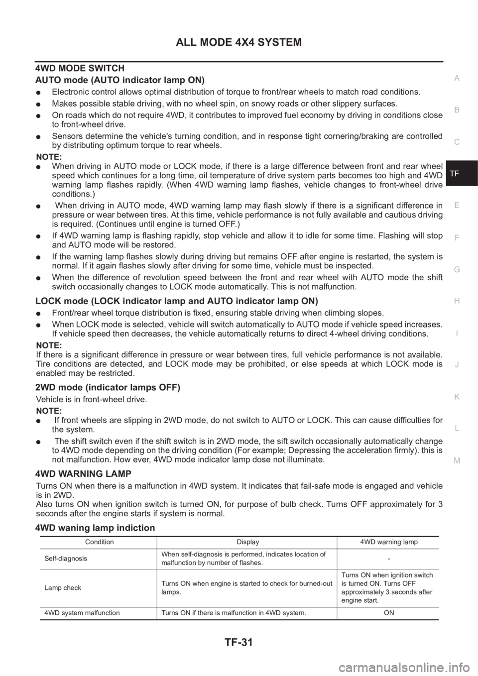
4WD MODE SWITCH
AUTO mode (AUTO indicator lamp ON)
●Electronic control allows optimal distribution of torque to front/rear wheels to match road conditions.
●Makes possible stable driving, with no wheel spin, on snowy roads or other slippery surfaces.
●On roads which do not require 4WD, it contributes to improved fuel economy by driving in conditions close
to front-wheel drive.
●Sensors determine the vehicle's turning condition, and in response tight cornering/braking are controlled
by distributing optimum torque to rear wheels.
NOTE:
●When driving in AUTO mode or LOCK mode, if there is a large difference between front and rear wheel
speed which continues for a long time, oil temperature of drive system parts becomes too high and 4WD
warning lamp flashes rapidly. (When 4WD warning lamp flashes, vehicle changes to front-wheel drive
conditions.)
● When driving in AUTO mode, 4WD warning lamp may flash slowly if there is a significant difference in
pressure or wear between tires. At this time, vehicle performance is not fully available and cautious driving
is required. (Continues until engine is turned OFF.)
●If 4WD warning lamp is flashing rapidly, stop vehicle and allow it to idle for some time. Flashing will stop
and AUTO mode will be restored.
●If the warning lamp flashes slowly during driving but remains OFF after engine is restarted, the system is
normal. If it again flashes slowly after driving for some time, vehicle must be inspected.
●When the difference of revolution speed between the front and rear wheel with AUTO mode the shift
switch occasionally changes to LOCK mode automatically. This is not malfunction.
LOCK mode (LOCK indicator lamp and AUTO indicator lamp ON)
●Front/rear wheel torque distribution is fixed, ensuring stable driving when climbing slopes.
●When LOCK mode is selected, vehicle will switch automatically to AUTO mode if vehicle speed increases.
If vehicle speed then decreases, the vehicle automatically returns to direct 4-wheel driving conditions.
NOTE:
If there is a significant difference in pressure or wear between tires, full vehicle performance is not available.
Tire conditions are detected, and LOCK mode may be prohibited, or else speeds at which LOCK mode is
enabled may be restricted.
2WD mode (indicator lamps OFF)
Vehicle is in front-wheel drive.
NOTE:
● If front wheels are slipping in 2WD mode, do not switch to AUTO or LOCK. This can cause difficulties for
the system.
● The shift switch even if the shift switch is in 2WD mode, the sift switch occasionally automatically change
to 4WD mode depending on the driving condition (For example; Depressing the acceleration firmly). this is
not malfunction. How ever, 4WD mode indicator lamp dose not illuminate.
4WD WARNING LAMP
Turns ON when there is a malfunction in 4WD system. It indicates that fail-safe mode is engaged and vehicle
is in 2WD.
Also turns ON when ignition switch is turned ON, for purpose of bulb check. Turns OFF approximately for 3
seconds after the engine starts if system is normal.
4WD waning lamp indiction
Condition Display 4WD warning lamp
Self-diagnosisWhen self-diagnosis is performed, indicates location of
malfunction by number of flashes.-
Lamp checkTurns ON when engine is started to check for burned-out
lamps.Turns ON when ignition switch
is turned ON. Turns OFF
approximately 3 seconds after
engine start.
4WD system malfunction Turns ON if there is malfunction in 4WD system. ON
Page 2643 of 3833
ALL MODE 4X4 SYSTEM
TF-33
C
E
F
G
H
I
J
K
L
MA
B
TF
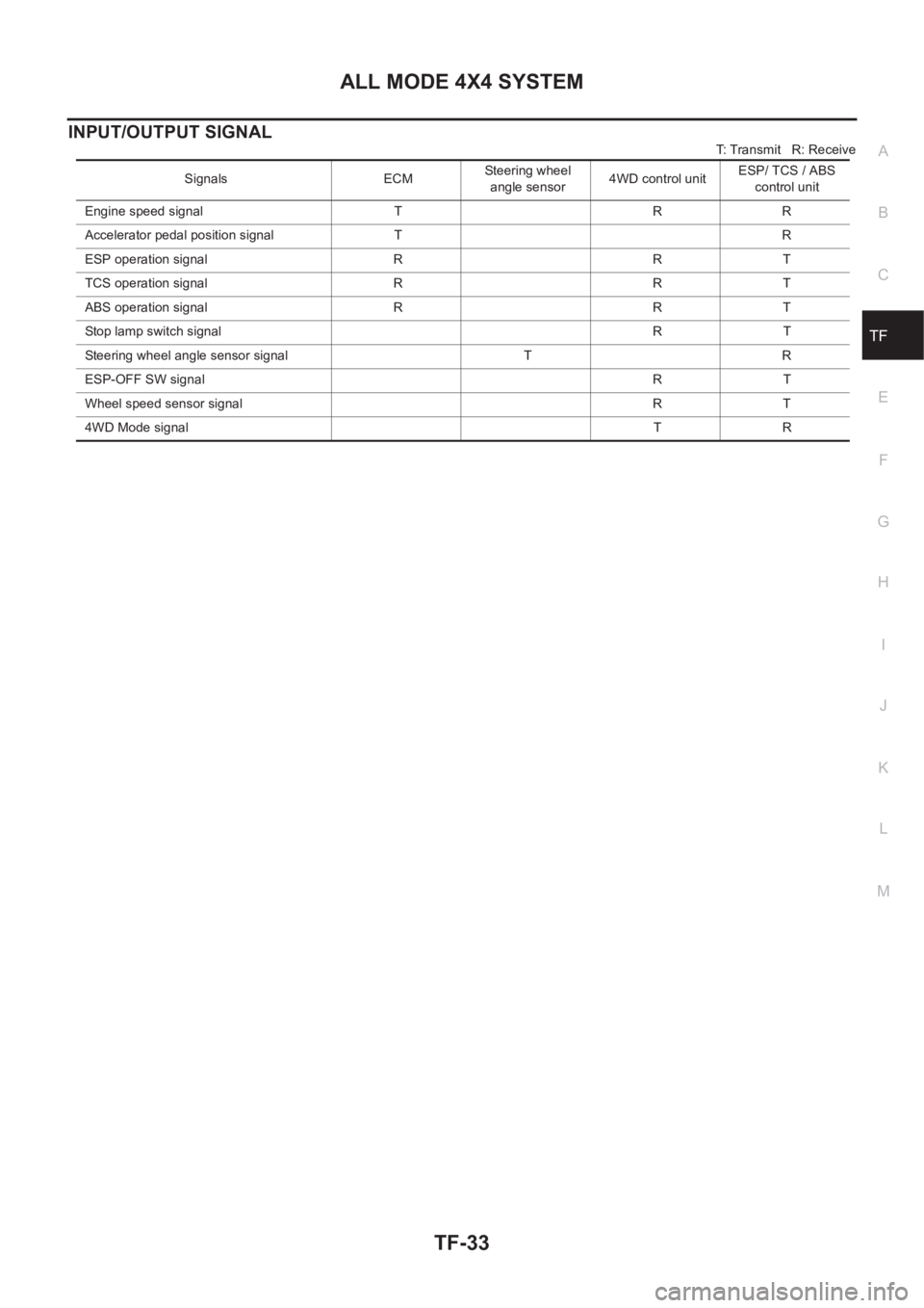
INPUT/OUTPUT SIGNAL
T: Transmit R: Receive
Signals ECMSteering wheel
angle sensor4WD control unitESP/ TCS / ABS
control unit
Engine speed signal T R R
Accelerator pedal position signal T R
ESP operation signal R R T
TCS operation signal R R T
ABS operation signal R R T
Stop lamp switch signalRT
Steering wheel angle sensor signal T R
ESP-OFF SW signalRT
Wheel speed sensor signal R T
4WD Mode signalTR
Page 2651 of 3833
TROUBLE DIAGNOSIS
TF-41
C
E
F
G
H
I
J
K
L
MA
B
TF
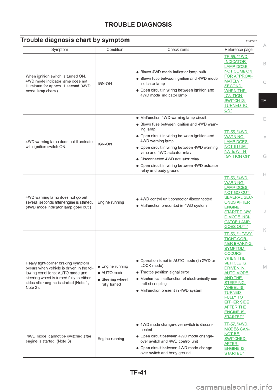
Trouble diagnosis chart by symptomEDS000IT
Symptom Condition Check items Reference page
When ignition switch is turned ON,
4WD mode indicator lamp does not
illuminate for approx. 1 second (4WD
mode lamp check)IGN-ON
●Blown 4WD mode indicator lamp bulb
●Blown fuse between ignition and 4WD mode
indicator lamp
●Open circuit in wiring between ignition and
4WD mode indicator lampTF-55, "
4WD
INDICATOR
LAMP DOSE
NOT COME ON
FOR APPROXI-
MATELY 1
SECOND
WHEN THE
IGNITION
SWITCH IS
TURNED TO
ON"
4WD warning lamp does not illuminate
with ignition switch ON.IGN-ON
●Malfunction 4WD warning lamp circuit.
●Blown fuse between ignition and 4WD warn-
ing lamp
●Open circuit in wiring between ignition and
4WD warning lamp
●Open circuit in wiring between 4WD warning
lamp and 4WD actuator relay
●Disconnected 4WD actuator relay
●Open circuit in wiring between 4WD actuator
relay and body groundTF-55, "
4WD
WARNING
LAMP DOES
NOT ILLUMI-
NATE WITH
IGNITION ON"
4WD warning lamp does not go out
several seconds after engine is started.
(4WD mode indicator lamp goes out.)Engine running●4WD control unit connector disconnected
●Malfunction presented in 4WD systemTF-56, "
4WD
WARNING
LAMP DOES
NOT GO OUT
SEVERAL SEC-
ONDS AFTER
ENGINE
STARTED.(4W
D MODE INDI-
CATOR LAMP
GOES OUT)"
Heavy tight-corner braking symptom
occurs when vehicle is driven in the fol-
lowing conditions: AUTO mode and
steering wheel is turned fully to either
sides after engine is started (Note 1,
Note 2).●Engine running
●AUTO mode
●Steering wheel
fully turned
●Operation is not in AUTO mode (in 2WD or
LOCK mode).
●Throttle position signal error
●Mechanical malfunction of electronically con-
trolled coupling
●Malfunction present in 4WD systemTF-56, "
HEAVY
TIGHT-COR-
NER BRAKING
SYMPTOM
OCCURS
WHEN THE
VEHICLE IS
DRIVEN IN
AUTO MODE
AND THE
STEERING
WHEEL IS
TURNED
FULLY TO
EITHER SIDE
AFTER THE
ENGINE IS
STARTED"
4WD mode cannot be switched after
engine is started (Note 3)Engine running
●4WD mode change-over switch is discon-
nected.
●Open circuit between 4WD mode change-
over switch and 4WD control unit
●Open circuit between 4WD mode change-
over switch and body groundTF-57, "
4WD
MODES CAN-
NOT BE
SWITCHED
AFTER
ENGINE IS
STARTED"
Page 2652 of 3833
TF-42
TROUBLE DIAGNOSIS
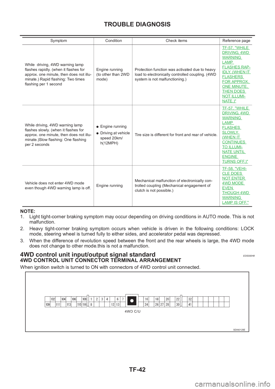
NOTE:
1. Light tight-corner braking symptom may occur depending on driving conditions in AUTO mode. This is not
malfunction.
2. Heavy tight-corner braking symptom occurs when vehicle is driven in the following conditions: LOCK
mode, steering wheel is turned fully to either sides, and accelerator pedal was depressed.
3. When the difference of revolution speed between the front and the rear wheels is large, the 4WD mode
does not change to other mode.this is not a malfunction.
4WD control unit input/output signal standardEDS000H9
4WD CONTROL UNIT CONNECTOR TERMINAL ARRANGEMENT
When ignition switch is turned to ON with connectors of 4WD control unit connected.
While driving, 4WD warning lamp
flashes rapidly. (when it flashes for
approx. one minute, then does not illu-
minate.) Rapid flashing: Two times
flashing per 1 secondEngine running
(to other than 2WD
mode)Protection function was activated due to heavy
load to electronically controlled coupling. (4WD
system is not malfunctioning.)TF-57, "
WHILE
DRIVING, 4WD
WARNING
LAMP
FLASHES RAP-
IDLY. (WHEN IT
FLASHERS
FOR APPROX.
ONE MINUTE,
THEN DOES
NOT ILLUMI-
NATE.)"
While driving, 4WD warning lamp
flashes slowly. (when it flashes for
approx. one minute, then does not illu-
minate.)Slow flashing: One flashing
per 2 seconds●Engine running
●Driving at vehicle
speed 20km/
h(12MPH)Tire size is different for front and rear of vehicle.TF-57, "
WHILE
DRIVING, 4WD
WARNING
LAMP
FLASHES
SLOWLY.
(WHEN IT
CONTINUES
TO ILLUMI-
NATE UNTIL
ENGINE
TURNS OFF.)"
Vehicle does not enter 4WD mode
even though 4WD warning lamp is off.Engine runningMechanical malfunction of electronically con-
trolled coupling (Mechanical engagement of
clutch is not possible.)TF-58, "
VEHI-
CLE DOES
NOT ENTER
4WD MODE
EVEN
THOUGH 4WD
WARNING
LAMP IS OFF."
Symptom Condition Check items Reference page
SDIA0120E
Page 2653 of 3833
TROUBLE DIAGNOSIS
TF-43
C
E
F
G
H
I
J
K
L
MA
B
TF
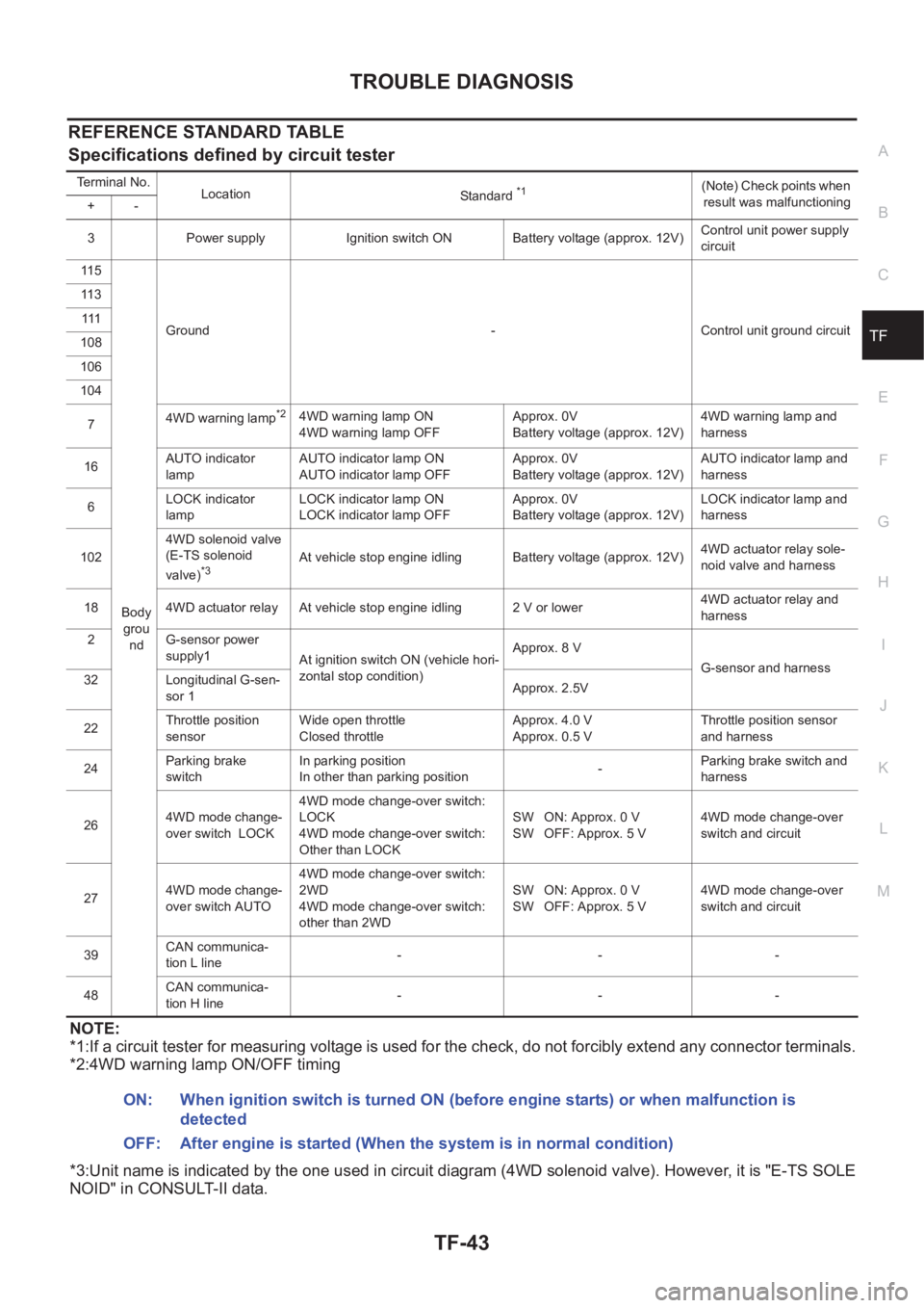
REFERENCE STANDARD TABLE
Specifications defined by circuit tester
NOTE:
*1:If a circuit tester for measuring voltage is used for the check, do not forcibly extend any connector terminals.
*2:4WD warning lamp ON/OFF timing
*3:Unit name is indicated by the one used in circuit diagram (4WD solenoid valve). However, it is "E-TS SOLE
NOID" in CONSULT-II data.
Terminal No.
Location
Standard *1(Note) Check points when
result was malfunctioning
+-
3 Power supply Ignition switch ON Battery voltage (approx. 12V)Control unit power supply
circuit
11 5
Body
grou
ndGround - Control unit ground circuit 11 3
111
108
106
104
74WD warning lamp
*24WD warning lamp ON
4WD warning lamp OFFApprox. 0V
Battery voltage (approx. 12V)4WD warning lamp and
harness
16AUTO indicator
lampAUTO indicator lamp ON
AUTO indicator lamp OFFApprox. 0V
Battery voltage (approx. 12V)AUTO indicator lamp and
harness
6LOCK indicator
lampLOCK indicator lamp ON
LOCK indicator lamp OFFApprox. 0V
Battery voltage (approx. 12V)LOCK indicator lamp and
harness
1024WD solenoid valve
(E-TS solenoid
valve)
*3At vehicle stop engine idling Battery voltage (approx. 12V)4WD actuator relay sole-
noid valve and harness
18 4WD actuator relay At vehicle stop engine idling 2 V or lower4WD actuator relay and
harness
2 G-sensor power
supply1
At ignition switch ON (vehicle hori-
zontal stop condition)Approx. 8 V
G-sensor and harness
32 Longitudinal G-sen-
sor 1Approx. 2.5V
22Throttle position
sensorWide open throttle
Closed throttleApprox. 4.0 V
Approx. 0.5 VThrottle position sensor
and harness
24Parking brake
switchIn parking position
In other than parking position-Parking brake switch and
harness
264WD mode change-
over switch LOCK4WD mode change-over switch:
LOCK
4WD mode change-over switch:
Other than LOCKSW ON: Approx. 0 V
SW OFF: Approx. 5 V4WD mode change-over
switch and circuit
274WD mode change-
over switch AUTO4WD mode change-over switch:
2WD
4WD mode change-over switch:
other than 2WDSW ON: Approx. 0 V
SW OFF: Approx. 5 V4WD mode change-over
switch and circuit
39CAN communica-
tion L line---
48CAN communica-
tion H line---
ON: When ignition switch is turned ON (before engine starts) or when malfunction is
detected
OFF: After engine is started (When the system is in normal condition)
Page 2654 of 3833
TF-44
TROUBLE DIAGNOSIS
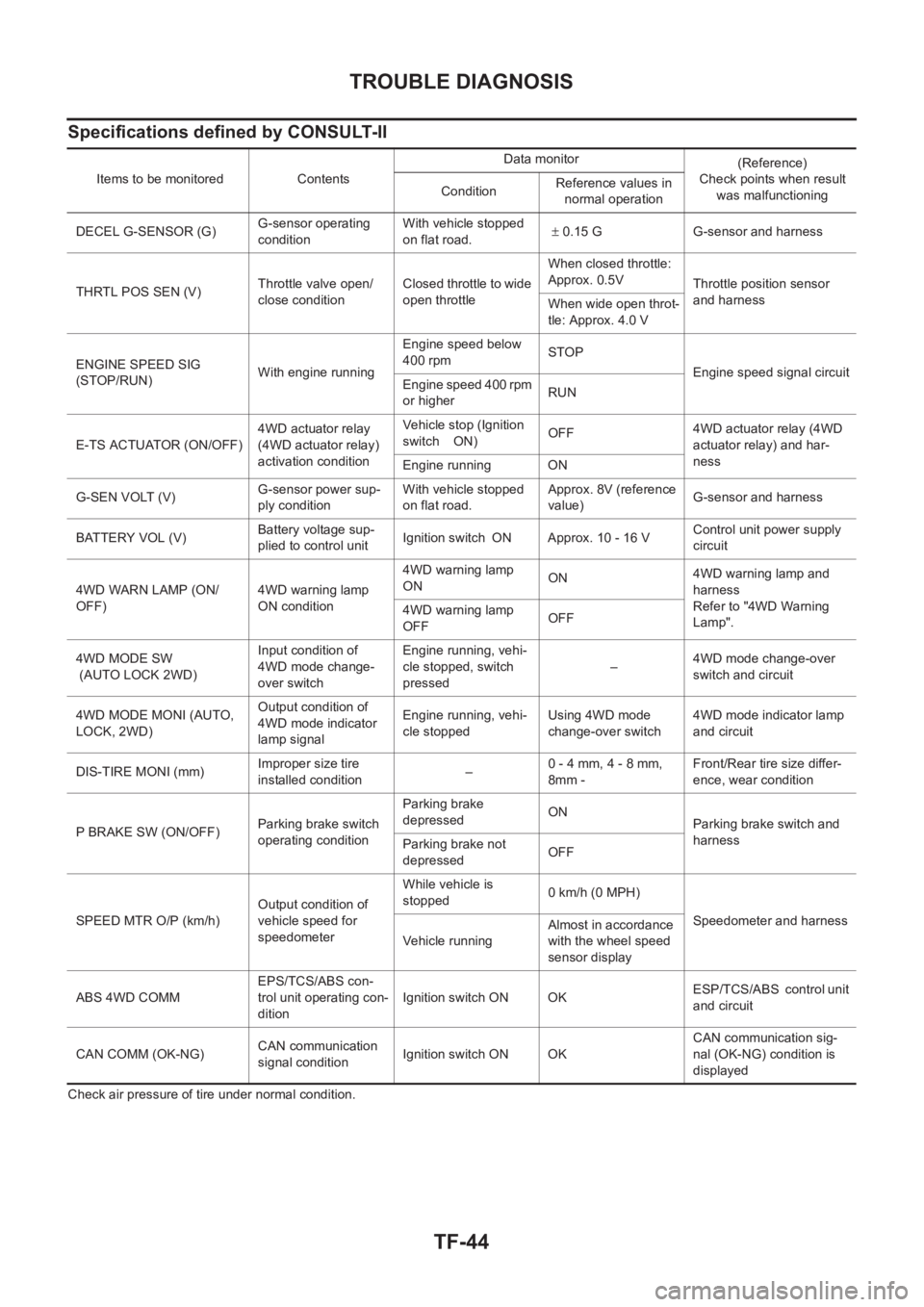
Specifications defined by CONSULT-II
Check air pressure of tire under normal condition.Items to be monitored ContentsData monitor
(Reference)
Check points when result
was malfunctioning ConditionReference values in
normal operation
DECEL G-SENSOR (G)G-sensor operating
conditionWith vehicle stopped
on flat road.± 0.15 G G-sensor and harness
THRTL POS SEN (V)Throttle valve open/
close conditionClosed throttle to wide
open throttleWhen closed throttle:
Approx. 0.5V
Throttle position sensor
and harness
When wide open throt-
tle: Approx. 4.0 V
ENGINE SPEED SIG
(STOP/RUN)With engine runningEngine speed below
400 rpmSTOP
Engine speed signal circuit
Engine speed 400 rpm
or higherRUN
E-TS ACTUATOR (ON/OFF)4WD actuator relay
(4WD actuator relay)
activation conditionVehicle stop (Ignition
switch ON)OFF4WD actuator relay (4WD
actuator relay) and har-
ness
Engine running ON
G-SEN VOLT (V)G-sensor power sup-
ply conditionWith vehicle stopped
on flat road.Approx. 8V (reference
value)G-sensor and harness
BATTERY VOL (V)Battery voltage sup-
plied to control unitIgnition switch ON Approx. 10 - 16 VControl unit power supply
circuit
4WD WARN LAMP (ON/
OFF)4WD warning lamp
ON condition4WD warning lamp
ONON4WD warning lamp and
harness
Refer to "4WD Warning
Lamp". 4WD warning lamp
OFFOFF
4WD MODE SW
(AUTO LOCK 2WD)Input condition of
4WD mode change-
over switchEngine running, vehi-
cle stopped, switch
pressed–4WD mode change-over
switch and circuit
4WD MODE MONI (AUTO,
LOCK, 2WD)Output condition of
4WD mode indicator
lamp signalEngine running, vehi-
cle stoppedUsing 4WD mode
change-over switch4WD mode indicator lamp
and circuit
DIS-TIRE MONI (mm)Improper size tire
installed condition
–0 - 4 mm, 4 - 8 mm,
8mm -Front/Rear tire size differ-
ence, wear condition
P BRAKE SW (ON/OFF)Parking brake switch
operating conditionParking brake
depressedON
Parking brake switch and
harness
Parking brake not
depressedOFF
SPEED MTR O/P (km/h)Output condition of
vehicle speed for
speedometerWhile vehicle is
stopped 0 km/h (0 MPH)
Speedometer and harness
Ve h i c le r u n n in gAlmost in accordance
with the wheel speed
sensor display
ABS 4WD COMMEPS/TCS/ABS con-
trol unit operating con-
ditionIgnition switch ON OKESP/TCS/ABS control unit
and circuit
CAN COMM (OK-NG)CAN communication
signal conditionIgnition switch ON OKCAN communication sig-
nal (OK-NG) condition is
displayed