2001 NISSAN X-TRAIL brake light
[x] Cancel search: brake lightPage 2893 of 3833
![NISSAN X-TRAIL 2001 Service Repair Manual TROUBLE DIAGNOSIS
BRC-109
[ESP/TCS/ABS]
C
D
E
G
H
I
J
K
L
MA
B
BRC
2.SELF-DIAGNOSIS RESULT CHECK 2
Turn the ignition switch OFF, and ON to erase the self-diagnosis results. And perform the ESP/TCS/ABS](/manual-img/5/57405/w960_57405-2892.png "NISSAN X-TRAIL 2001 Service Repair Manual TROUBLE DIAGNOSIS
BRC-109
[ESP/TCS/ABS]
C
D
E
G
H
I
J
K
L
MA
B
BRC
2.SELF-DIAGNOSIS RESULT CHECK 2
Turn the ignition switch OFF, and ON to erase the self-diagnosis results. And perform the ESP/TCS/ABS")
TROUBLE DIAGNOSIS
BRC-109
[ESP/TCS/ABS]
C
D
E
G
H
I
J
K
L
MA
B
BRC
2.SELF-DIAGNOSIS RESULT CHECK 2
Turn the ignition switch OFF, and ON to erase the self-diagnosis results. And perform the ESP/TCS/ABS con-
trol unit self-diagnosis again.
Is the same self-diagnosis item indicated again?
YES >> After replacing the spiral cable (with the steering wheel angle sensor), perform the neutral position
adjustment. Then conduct the self-diagnosis again.
NO >> Inspection End
Inspection 14 Brake Fluid Level of Reservoir Tank, Communication Circuit
between ESP/TCS/ABS Control Unit and Brake Fluid Level Warning Switch
EFS001AQ
Inspection procedure
1.SELF-DIAGNOSIS RESULT CHECK 1
Check the self-diagnosis results.
Does the brake warning light turn on?
YES >> Check the pad for wear. Check the brake fluid for leakage.
NO >> GO TO 2.
2.SELF-DIAGNOSIS RESULT CHECK 2
1. Disconnect connectors for the brake fluid level warning switch and the ESP/TCS/ABS control unit.
2. Securely connect connectors. Perform the ESP/TCS/ABS control unit self-diagnosis again.
Is the same self-diagnosis item indicated again?
YES >> GO TO 3.
NO >> Poor connection of connector. Repair or replace the poorly connected connector.
3.CIRCUIT CHECK BETWEEN BRAKE FLUID LEVEL WARNING SWITCH AND ESP/TCS/ABS CON-
TROL UNIT
1. Disconnect connectors for the brake fluid level warning switch
and the ESP/TCS/ABS control unit.
2. Check for continuity between the brake fluid level warning switch (vehicle-side connector E19) and the
ESP/TCS/ABS control unit (vehicle-side connector B111).
Is inspection result OK?
YES >> Perform the ESP/TCS/ABS control unit self-diagnosis again.
NO >> Repair or replace the disconnected harness.
Self-diagnosis results
CONSUL-II indication item
BR FLUID LEVER LOW
SFIA0925E
ESP/TCS/ABS control unit
(Vehicle-side connector B111)Brake fluid level warning switch
(Vehicle-side connector E19)Continuity
40 (Y/B) 1 (Y/B) Yes
Page 2898 of 3833
![NISSAN X-TRAIL 2001 Service Repair Manual BRC-114
[ESP/TCS/ABS]
TROUBLE DIAGNOSIS
Actuator operation check
1. Connect 9 and 10 terminals of actuator to 40 and 41 terminals of
relay box.
2. Measure the motor voltage (No.4 terminal to bo](/manual-img/5/57405/w960_57405-2897.png "NISSAN X-TRAIL 2001 Service Repair Manual BRC-114
[ESP/TCS/ABS]
TROUBLE DIAGNOSIS
Actuator operation check
1. Connect 9 and 10 terminals of actuator to 40 and 41 terminals of
relay box.
2. Measure the motor voltage (No.4 terminal to bo")
BRC-114
[ESP/TCS/ABS]
TROUBLE DIAGNOSIS
Actuator operation check
1. Connect 9 and 10 terminals of actuator to 40 and 41 terminals of
relay box.
2. Measure the motor voltage (No.4 terminal to body earth) with
oscilloscope. Then check the motor reverse voltage occasioned
time.
The motor reverse voltage occasioned time is more than 0.1
sec.
CAUTION:
●Perform checking of motor relay unit. Then confirm that
relay functions.
●Driving actuator motor is with in 4 sec. to prevent heating
up.
●Standard condition of the motor reverse voltage occa-
sioned time is: Battery voltage is 12V. Temperature 20°.
when the battery voltage or temperature is lower than the
standard, the motor reverse voltage occasioned time
becomes slightly shorter.
Symptom 1: ABS Works Frequently.EFS001AS
Inspection procedure
1. INSPECTION START
Check the wheel sensor system.
●Sensor mounting inspection
●Sensor pick-up inspection for iron chips
●Sensor rotor inspection (e.g. Number of teeth, damaged teeth)
●Sensor connector engagement inspection
Is inspection result OK?
YES >> GO TO 2.
NO >> Refer to wheel sensor and rotor lines.
2. LOOSENESS INSPECTION
Check the front axle for looseness.
Is inspection result OK?
YES >>BRC-114, "Symptom 2: Unexpected Pedal Action"
NO >> Axle inspection and repair
Symptom 2: Unexpected Pedal ActionEFS001AT
Inspection procedure
1. BRAKE PEDAL STROKE INSPECTION
Check the brake pedal stroke.
Is stroke excessively long?
YES >> Check the bleeding and brake system.
NO >> GO TO 2.
SFIA0910E
Page 2900 of 3833
![NISSAN X-TRAIL 2001 Service Repair Manual BRC-116
[ESP/TCS/ABS]
TROUBLE DIAGNOSIS
4. WHEEL SENSOR INSPECTION
Check the wheel sensor system.
●Sensor mounting inspection
●Sensor pick-up inspection for iron chips
●Sensor rotor inspection (](/manual-img/5/57405/w960_57405-2899.png "NISSAN X-TRAIL 2001 Service Repair Manual BRC-116
[ESP/TCS/ABS]
TROUBLE DIAGNOSIS
4. WHEEL SENSOR INSPECTION
Check the wheel sensor system.
●Sensor mounting inspection
●Sensor pick-up inspection for iron chips
●Sensor rotor inspection (")
BRC-116
[ESP/TCS/ABS]
TROUBLE DIAGNOSIS
4. WHEEL SENSOR INSPECTION
Check the wheel sensor system.
●Sensor mounting inspection
●Sensor pick-up inspection for iron chips
●Sensor rotor inspection (e.g. Number of teeth, damaged teeth)
●Sensor connector engagement inspection
Is inspection result OK?
YES >> Normal
NO >> Wheel sensor and rotor lines repair
Symptom 4: ABS Does Not Work.EFS001AV
Inspection procedure
1. ABS WARNING LAMP INDICATOR INSPECTION
Check that the ABS warning lamp illuminates.
Does the ABS warning lamp illuminate?
YES >> Perform the self-diagnosis.
NO >> GO TO 2.
2. WHEEL SENSOR INSPECTION
Check the wheel sensor system.
●Sensor mounting inspection
●Sensor pick-up inspection for iron chips
●Sensor rotor inspection (e.g. Number of teeth, damaged teeth)
●Sensor connector engagement inspection
Is inspection result OK?
YES >> Normal
NO >> Wheel sensor and rotor lines repair
Symptom 5: Pedal Vibration and NoiseEFS001AW
Inspection procedure
1. SYMPTOM CHECK
Check the brake system for pedal vibration or noise at the engine start.
Is inspection result OK?
YES >> Perform the self-diagnosis.
NO >> GO TO 2.
2. SYMPTOM CHECK 2
Check the brake system for pedal vibration or noise when the pedal depressed lightly (just put a foot on).
CAUTION:
Under the following driving conditions, the wheel speed will fluctuates, resulting in ABS activation.
●When shifting gears
●High speed cornering
●When a gust of wind
Is inspection result OK?
YES >> GO TO 3.
NO >> Normal
Page 2916 of 3833
PS-6
STEERING WHEEL
STEERING WHEEL
PFP:48430
On-Vehicle Inspection and ServiceEGS0004E
PLAY INSPECTION
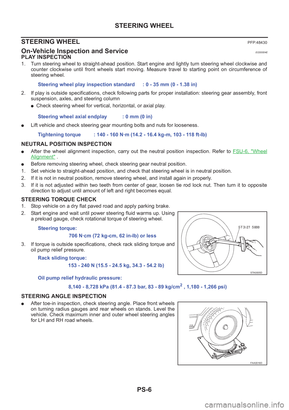
1. Turn steering wheel to straight-ahead position. Start engine and lightly turn steering wheel clockwise and
counter clockwise until front wheels start moving. Measure travel to starting point on circumference of
steering wheel.
2. If play is outside specifications, check following parts for proper installation: steering gear assembly, front
suspension, axles, and steering column
●Check steering wheel for vertical, horizontal, or axial play.
●Lift vehicle and check steering gear mounting bolts and nuts for looseness.
NEUTRAL POSITION INSPECTION
●After the wheel alignment inspection, carry out the neutral position inspection. Refer to FSU-6, "Wheel
Alignment" .
●Before removing steering wheel, check steering gear neutral position.
1. Set vehicle to straight-ahead position, and check that steering wheel is in neutral position.
2. If it is not in neutral position, remove steering wheel, and install again in properly.
3. If it is not adjusted within two teeth from center of gear, loosen tie rod lock nut. Then turn it to opposite
direction to adjust until amount of left and right becomes equal.
STEERING TORQUE CHECK
1. Stop vehicle on a dry flat paved road and apply parking brake.
2. Start engine and wait until power steering fluid warms up. Using
a preload gauge, check rotational torque of steering wheel.
3. If torque is outside specifications, check rack sliding torque and
oil pump relief pressure.
STEERING ANGLE INSPECTION
●After toe-in inspection, check steering angle. Place front wheels
on turning radius gauges and rear wheels on stands. Level the
vehicle. Check maximum inner and outer wheel steering angles
for LH and RH road wheels.Steering wheel play inspection standard : 0 - 35 mm (0 - 1.38 in)
Steering wheel axial endplay : 0 mm (0 in)
Tightening torque : 140 - 160 N·m (14.2 - 16.4 kg-m, 103 - 118 ft-lb)
Steering torque:
706 N·cm (72 kg-cm, 62 in-lb) or less
Rack sliding torque:
153 - 240 N (15.5 - 24.5 kg, 34.3 - 54.2 lb)
Oil pump relief hydraulic pressure:
8,140 - 8,728 kPa (81.4 - 87.3 bar, 83 - 89 kg/cm
2 , 1,180 - 1,266 psi)
STA0005D
FAA0016D
Page 3764 of 3833
PG-60
HARNESS
Wiring Diagram Codes (Cell Codes)
EKS0032J
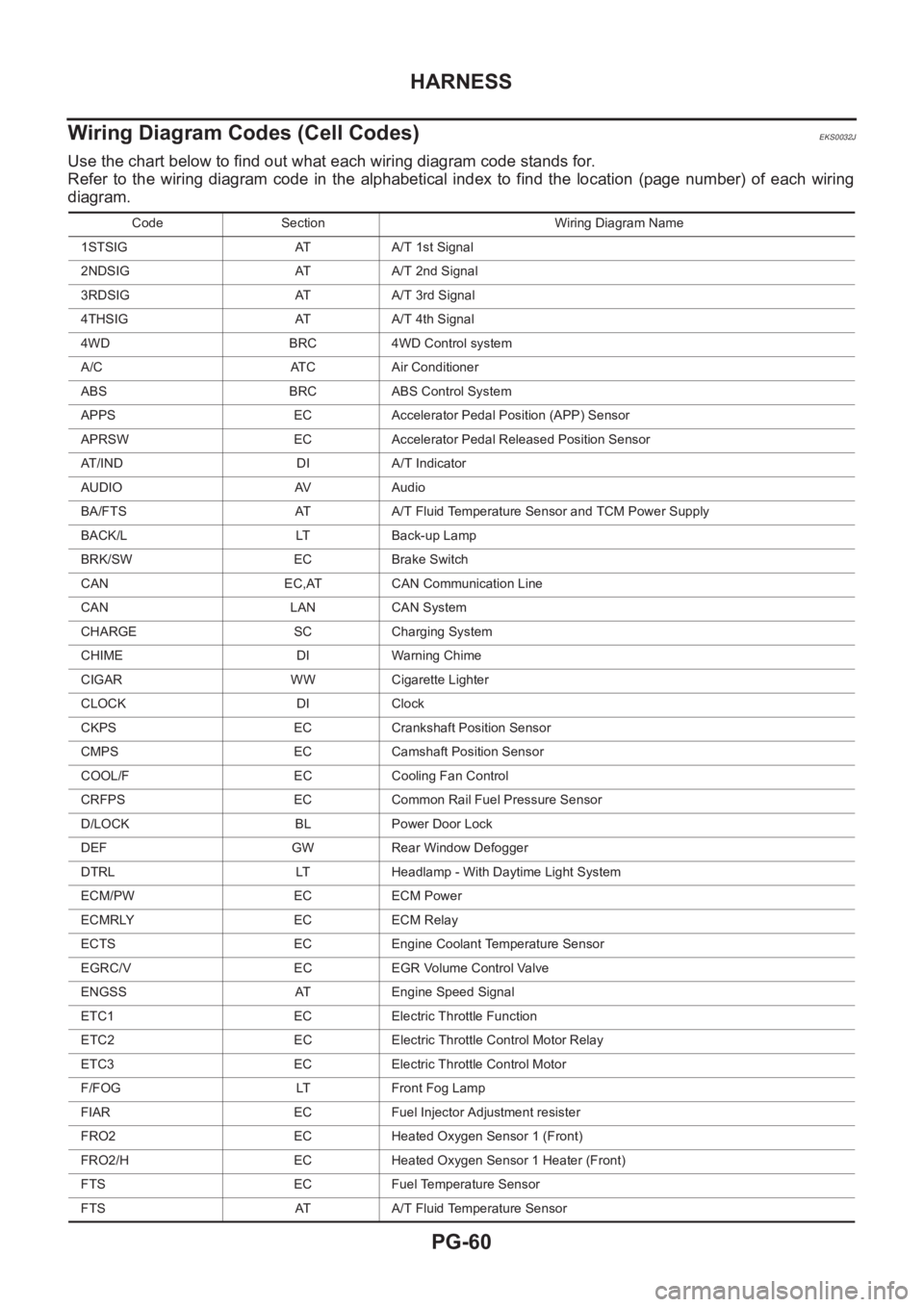
Use the chart below to find out what each wiring diagram code stands for.
Refer to the wiring diagram code in the alphabetical index to find the location (page number) of each wiring
diagram.
Code Section Wiring Diagram Name
1STSIG AT A/T 1st Signal
2NDSIG AT A/T 2nd Signal
3RDSIG AT A/T 3rd Signal
4THSIG AT A/T 4th Signal
4WD BRC 4WD Control system
A/C ATC Air Conditioner
ABS BRC ABS Control System
APPS EC Accelerator Pedal Position (APP) Sensor
APRSW EC Accelerator Pedal Released Position Sensor
AT/IND DI A/T Indicator
AUDIO AV Audio
BA/FTS AT A/T Fluid Temperature Sensor and TCM Power Supply
BACK/L LT Back-up Lamp
BRK/SW EC Brake Switch
CAN EC,AT CAN Communication Line
CAN LAN CAN System
CHARGE SC Charging System
CHIME DI Warning Chime
CIGAR WW Cigarette Lighter
CLOCK DI Clock
CKPS EC Crankshaft Position Sensor
CMPS EC Camshaft Position Sensor
COOL/F EC Cooling Fan Control
CRFPS EC Common Rail Fuel Pressure Sensor
D/LOCK BL Power Door Lock
DEF GW Rear Window Defogger
DTRL LT Headlamp - With Daytime Light System
ECM/PW EC ECM Power
ECMRLY EC ECM Relay
ECTS EC Engine Coolant Temperature Sensor
EGRC/V EC EGR Volume Control Valve
ENGSS AT Engine Speed Signal
ETC1 EC Electric Throttle Function
ETC2 EC Electric Throttle Control Motor Relay
ETC3 EC Electric Throttle Control Motor
F/FOG LT Front Fog Lamp
FIAR EC Fuel Injector Adjustment resister
FRO2 EC Heated Oxygen Sensor 1 (Front)
FRO2/H EC Heated Oxygen Sensor 1 Heater (Front)
FTS EC Fuel Temperature Sensor
FTS AT A/T Fluid Temperature Sensor
Page 3784 of 3833
MA-4
DESCRIPTION
DESCRIPTION
PFP:00000
Pre-delivery Inspection ItemsELS000AK
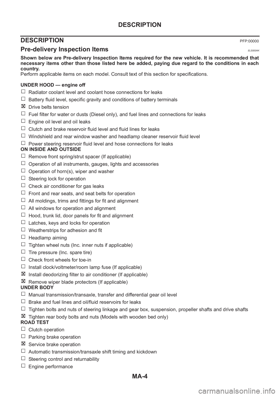
Shown below are Pre-delivery Inspection Items required for the new vehicle. It is recommended that
necessary items other than those listed here be added, paying due regard to the conditions in each
country.
Perform applicable items on each model. Consult text of this section for specifications.
UNDER HOOD — engine off
Radiator coolant level and coolant hose connections for leaks
Battery fluid level, specific gravity and conditions of battery terminals
Drive belts tension
Fuel filter for water or dusts (Diesel only), and fuel lines and connections for leaks
Engine oil level and oil leaks
Clutch and brake reservoir fluid level and fluid lines for leaks
Windshield and rear window washer and headlamp cleaner reservoir fluid level
Power steering reservoir fluid level and hose connections for leaks
ON INSIDE AND OUTSIDE
Remove front spring/strut spacer (If applicable)
Operation of all instruments, gauges, lights and accessories
Operation of horn(s), wiper and washer
Steering lock for operation
Check air conditioner for gas leaks
Front and rear seats, and seat belts for operation
All moldings, trims and fittings for fit and alignment
All windows for operation and alignment
Hood, trunk lid, door panels for fit and alignment
Latches, keys and locks for operation
Weatherstrips for adhesion and fit
Headlamp aiming
Tighten wheel nuts (Inc. inner nuts if applicable)
Tire pressure (Inc. spare tire)
Check front wheels for toe-in
Install clock/voltmeter/room lamp fuse (If applicable)
Install deodorizing filter to air conditioner (If applicable)
Remove wiper blade protectors (If applicable)
UNDER BODY
Manual transmission/transaxle, transfer and differential gear oil level
Brake and fuel lines and oil/fluid reservoirs for leaks
Tighten bolts and nuts of steering linkage and gear box, suspension, propeller shafts and drive shafts
Tighten rear body bolts and nuts (Models with wooden bed only)
ROAD TEST
Clutch operation
Parking brake operation
Service brake operation
Automatic transmission/transaxle shift timing and kickdown
Steering control and returnability
Engine performance
Page 3827 of 3833
IDX-3
A
C
D
E
F
G
H
I
J
K
L B
IDX
ALPHABETICAL INDEX
MTC-17,MTC-21
Blower resistor ................................................ MTC-22
Blower unit ...................................... ATC-116,MTC-21
Boring/horning cylinder block(QR20DE•QR25DE) .......
EM-93
Brake booster .................................................... BR-17
Brake fluid change ............................................... BR-9
Brake fluid level ................................................. MA-39
Brake fluid level and line check ........................... BR-9
Brake hydraulic line ........................................... BR-11
Brake inspection ................................................ MA-39
Brake lines and cables inspection ..................... MA-39
Brake master cylinder ........................................ BR-13
Brake pedal ......................................................... BR-6
Brake switch .... EC-349,EC-625,EC-1068,EC-1301,
EC-1558
BRK/SW - Wiring diagram EC-351,EC-627,EC-1070,
EC-1303
,EC-1559
Bulb specifications .............................................. LT-67
Bumper, front ......................................................... EI-6
Bumper, rear .......................................................... EI-9
C
Camshaft inspection(QR20DE•QR25DE) .......... EM-51
Camshaft inspection(YD22DDTi) .................... EM-159
Camshaft position sensor (CMPS) ................ EC-1484
Camshaft position sensor (PHASE) . EC-233,EC-557,
EC-962
,EC-1246
Camshaft(QR20DE•QR25DE) ........................... EM-46
Camshaft(YD22DDTi) ...................................... EM-158
CAN - Wiring diagram ......... EC-123,EC-514,EC-855,
EC-1200
,EC-1449,LAN-6,LAN-13
CAN (Controller Area Network) LAN-3,LAN-5,LAN-12
CAN Communication .......................................... TF-53
CAN communication ........... EC-122,EC-513,EC-854,
EC-1199
,EC-1448,AT-109,AT-190,AT-309,AT-403,
BRC-54
,BRC-62,BRC-92,BRC-110,LAN-3,LAN-5,
LAN-12
Canister-See EVAP canister ............ EC-427,EC-748,
EC-1114
,EC-1388
CHARGE - Wiring diagram ................................ SC-13
Charging system ................................................ SC-12
Chassis and body maintenance ........................ MA-35
CHIME - Wiring diagram ..................................... DI-59
CIGAR - Wiring diagram .................................. WW-25
Cigarette lighter ............................................... WW-25
Circuit breaker ................................................... PG-12
CKPS - Wiring diagram ................................. EC-1481
Clearance lamp ........................................ LT-4,LT-40
Clock ................................................................... DI-70
CLOCK - Wiring diagram .................................... DI-70
Closed loop control EC-34,EC-444,EC-766,EC-1130
Clutch cover ....................................................... CL-15
Clutch disc ......................................................... CL-15
Clutch master cylinder ......................................... CL-9
Clutch operating cylinder ................................... CL-11
Clutch pedal ......................................................... CL-5
Clutch release bearing ....................................... CL-13
Clutch release mechanism ................................ CL-13
Clutch withdrawal lever ...................................... CL-13
CMPS - Wiring diagram ................................. EC-1486
Coil spring (rear) ............................................... RSU-8
Collision diagnosis .......................................... SRS-47
Combination meter .................................... DI-4,DI-24
Combination switch ................................. LT-24,LT-44
Common rail fuel pressure sensor ................. EC-1468
Component Location (auto A/C) ......... ATC-34,MTC-4
Compression pressure(QR20DE•QR25DE) ..... EM-59
Compression pressure(YD22DDTi) ................ EM-182
Compressor clutch removal and installation .. ATC-135
Compressor special service tool ...................... ATC-14
Condenser ..................................................... ATC-143
Connecting rod bearing clearance(QR20DE•QR25DE)
EM-91
Connecting rod bearing clearance(YD22DDTi) EM-216
Connecting rod bushing clearance(QR20DE•QR25DE)
EM-91
Connecting rod bushing clearance(YD22DDTi) EM-210
Connecting rod(QR20DE•QR25DE) ................. EM-91
Connecting rod(YD22DDTi) .............. EM-207,EM-212
Console box - See Instrument panel .......... IP-3,IP-10
CONSULT for engine ........... EC-94,EC-486,EC-826,
EC-1173
,EC-1431
CONSULT for VDC ......................................... BRC-80
Control lever (M/T) ............................................. MT-13
Control unit ..................................... ATC-111,MTC-20
Control units (terminal arrangement) ................. PG-71
Controller Area Network (CAN) LAN-3,LAN-5,LAN-12
Converter housing installation ........... AT-419,AT-514
COOL/F - Wiring diagram EC-327,EC-607,EC-1054,
EC-1291
,EC-1510
Coolant replacement(QR20DE•QR25DE) ........ MA-19
Coolant replacement(YD22DDTi) ..................... MA-27
Cooling circuit (engine)(QR20DE•QR25DE) ....... CO-7
Cooling circuit (engine)(YD22DDTi) ................. CO-27
Cooling fan control system(QR20DE•QR25DE) CO-12
Cooling fan motor EC-336,EC-616,EC-1063,EC-1300
Cooling fan relay EC-336,EC-616,EC-1063,EC-1300
Cooling fan(QR20DE•QR25DE) ....................... CO-12
Cooling fan(YD22DDTi) .................................... CO-33
Coupling sleeve (M/T) ........................... MT-18,MT-23
Cowl top .............................................................. EI-12
Cowl top cover .................................................... EI-12
Crankcase ventilation system ........................ EC-1402
Crankcase ventilation system - See Positive crankcase
ventilation .......... EC-428
,EC-749,EC-1115,EC-1389
Crankshaft position sensor (POS) .... EC-227,EC-551,
EC-956
,EC-1240
Crankshaft position sensor (TDC) ................. EC-1479
Crankshaft(QR20DE•QR25DE) ........................ EM-74
CRFPS - Wiring diagram ............................... EC-1469
Cylinder block boring(QR20DE•QR25DE) ........ EM-94
Cylinder block boring(YD22DDTi) ................... EM-214
Cylinder block(QR20DE•QR25DE) ................... EM-73
Cylinder block(YD22DDTi) .............................. EM-197
Cylinder head bolt tightening(QR20DE•QR25DE) ........
EM-61