2001 NISSAN X-TRAIL diagram
[x] Cancel search: diagramPage 2079 of 3833
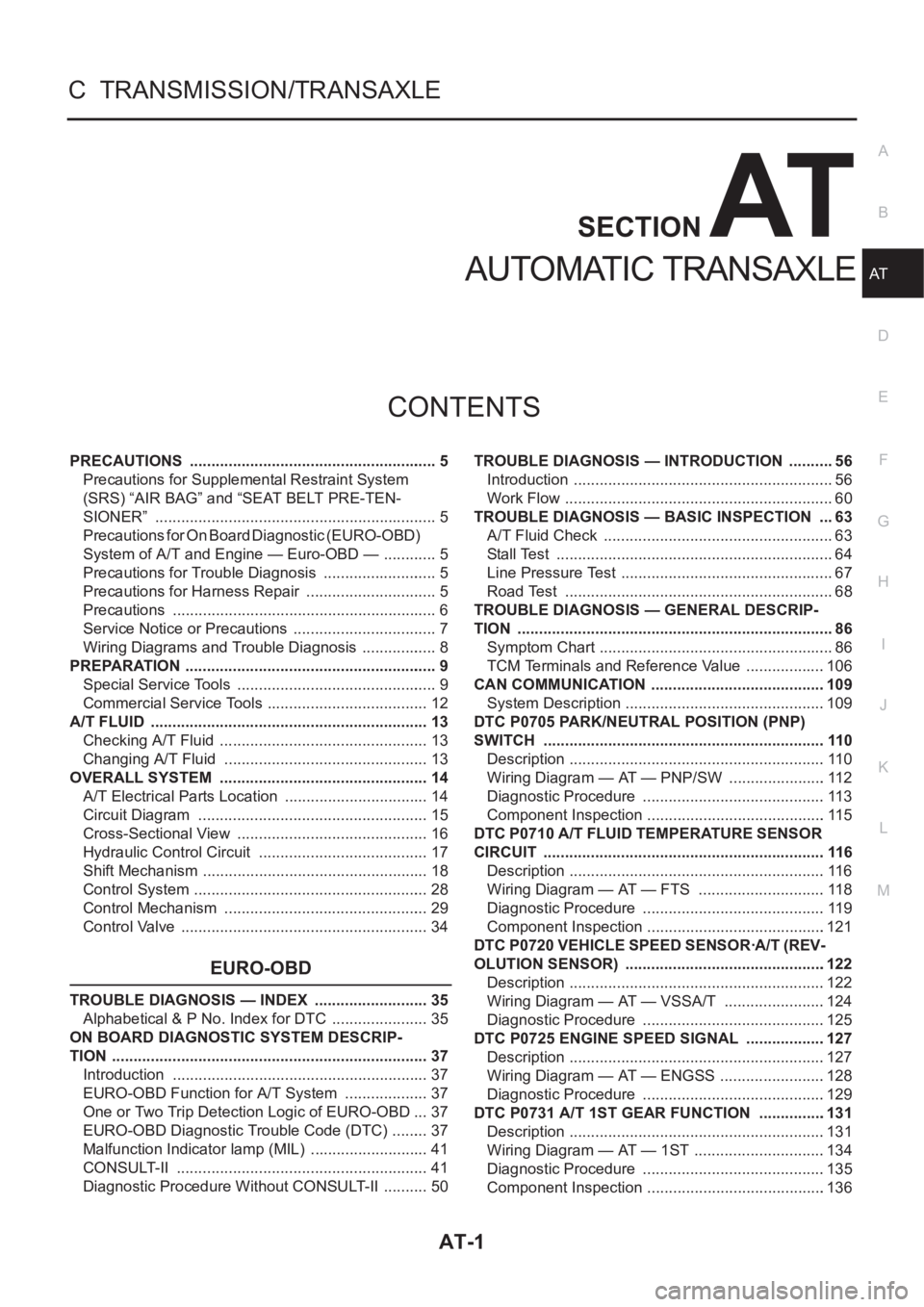
AT-1
AUTOMATIC TRANSAXLE
C TRANSMISSION/TRANSAXLE
CONTENTS
D
E
F
G
H
I
J
K
L
M
SECTION
A
B
AT
AUTOMATIC TRANSAXLE
PRECAUTIONS .......................................................... 5
Precautions for Supplemental Restraint System
(SRS) “AIR BAG” and “SEAT BELT PRE-TEN-
SIONER” .................................................................. 5
Precautions for On Board Diagnostic (EURO-OBD)
System of A/T and Engine — Euro-OBD — ............. 5
Precautions for Trouble Diagnosis ........................... 5
Precautions for Harness Repair ............................... 5
Precautions .............................................................. 6
Service Notice or Precautions .................................. 7
Wiring Diagrams and Trouble Diagnosis .................. 8
PREPARATION ........................................................... 9
Special Service Tools ............................................... 9
Commercial Service Tools ...................................... 12
A/T FLUID ................................................................. 13
Checking A/T Fluid ................................................. 13
Changing A/T Fluid ............................................. ... 13
OVERALL SYSTEM ................................................. 14
A/T Electrical Parts Location .................................. 14
Circuit Diagram ...................................................... 15
Cross-Sectional View ............................................. 16
Hydraulic Control Circuit ........................................ 17
Shift Mechanism ..................................................... 18
Control System ....................................................... 28
Control Mechanism ................................................ 29
Control Valve .......................................................... 34
EURO-OBD
TROUBLE DIAGNOSIS — INDEX ........................... 35
Alphabetical & P No. Index for DTC ....................... 35
ON BOARD DIAGNOSTIC SYSTEM DESCRIP-
TION .......................................................................... 37
Introduction ............................................................ 37
EURO-OBD Function for A/T System .................... 37
One or Two Trip Detection Logic of EURO-OBD ... 37
EURO-OBD Diagnostic Trouble Code (DTC) ......... 37
Malfunction Indicator lamp (MIL) ............................ 41
CONSULT-II ........................................................... 41
Diagnostic Procedure Without CONSULT-II ........... 50TROUBLE DIAGNOSIS — INTRODUCTION ........... 56
Introduction ............................................................. 56
Work Flow ............................................................... 60
TROUBLE DIAGNOSIS — BASIC INSPECTION .... 63
A/T Fluid Check ...................................................... 63
Stall Test ................................................................. 64
Line Pressure Test .................................................. 67
Road Test ............................................................... 68
TROUBLE DIAGNOSIS — GENERAL DESCRIP-
TION .......................................................................... 86
Symptom Chart ....................................................... 86
TCM Terminals and Reference Value ...................106
CAN COMMUNICATION .........................................109
System Description ...............................................109
DTC P0705 PARK/NEUTRAL POSITION (PNP)
SWITCH ..................................................................110
Description ............................................................110
Wiring Diagram — AT — PNP/SW .......................112
Diagnostic Procedure ...........................................113
Component Inspection ..........................................115
DTC P0710 A/T FLUID TEMPERATURE SENSOR
CIRCUIT ..................................................................116
Description ............................................................116
Wiring Diagram — AT — FTS ..............................118
Diagnostic Procedure ...........................................119
Component Inspection ..........................................121
DTC P0720 VEHICLE SPEED SENSOR·A/T (REV-
OLUTION SENSOR) ...............................................122
Description ............................................................122
Wiring Diagram — AT — VSSA/T ........................124
Diagnostic Procedure ...........................................125
DTC P0725 ENGINE SPEED SIGNAL ...................127
Description ............................................................127
Wiring Diagram — AT — ENGSS .........................128
Diagnostic Procedure ...........................................129
DTC P0731 A/T 1ST GEAR FUNCTION ...............
.131
Description ............................................................131
Wiring Diagram — AT — 1ST ...............................134
Diagnostic Procedure ...........................................135
Component Inspection ..........................................136
Page 2080 of 3833
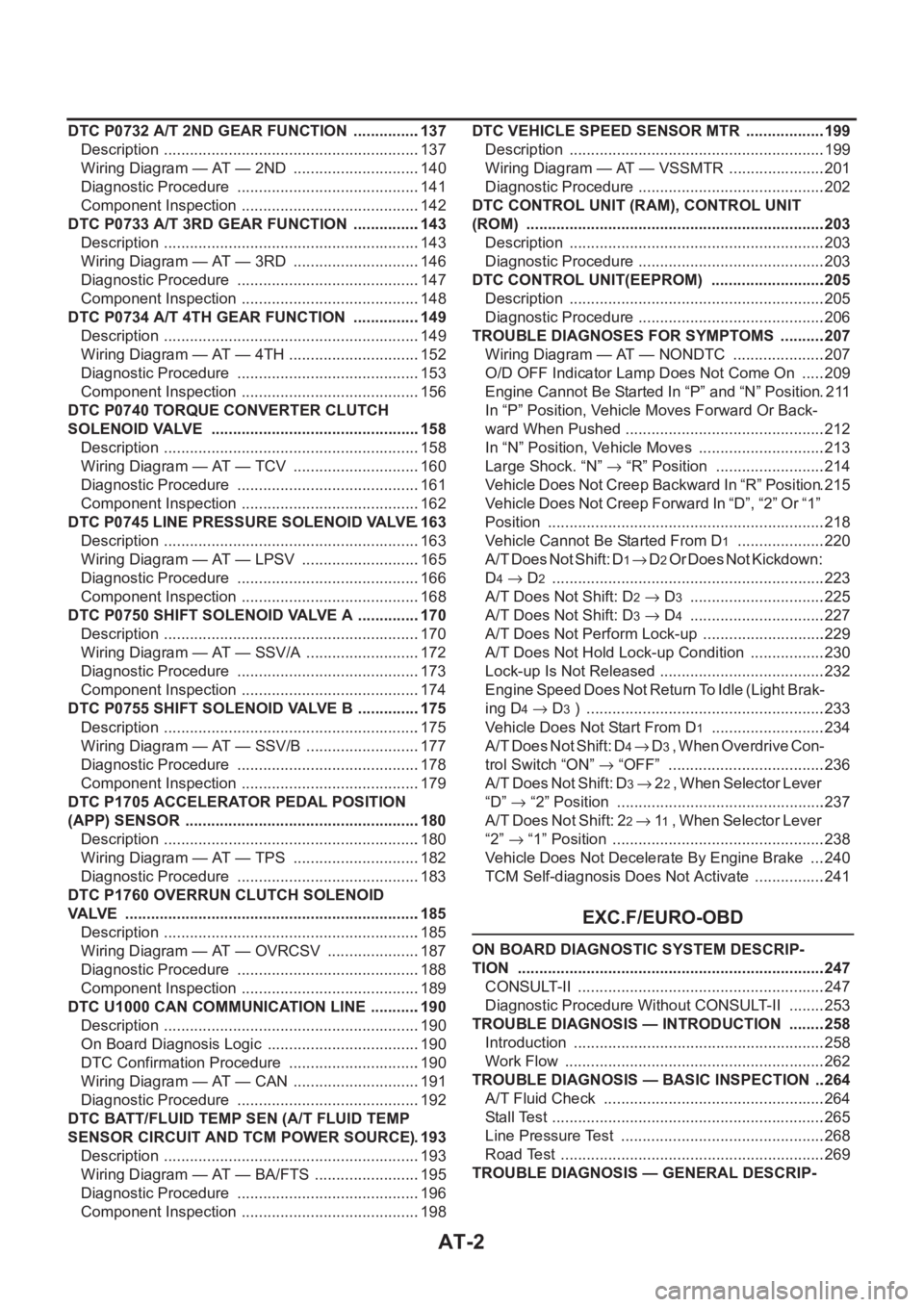
AT-2
DTC P0732 A/T 2ND GEAR FUNCTION ................137
Description ............................................................137
Wiring Diagram — AT — 2ND ..............................140
Diagnostic Procedure ...........................................141
Component Inspection ..........................................142
DTC P0733 A/T 3RD GEAR FUNCTION ................143
Description ............................................................143
Wiring Diagram — AT — 3RD ..............................146
Diagnostic Procedure ...........................................147
Component Inspection ..........................................148
DTC P0734 A/T 4TH GEAR FUNCTION ................149
Description ............................................................149
Wiring Diagram — AT — 4TH ...............................152
Diagnostic Procedure ...........................................153
Component Inspection ..........................................156
DTC P0740 TORQUE CONVERTER CLUTCH
SOLENOID VALVE .................................................158
Description ............................................................158
Wiring Diagram — AT — TCV ..............................160
Diagnostic Procedure ...........................................161
Component Inspection ..........................................162
DTC P0745 LINE PRESSURE SOLENOID VALVE .163
Description ............................................................163
Wiring Diagram — AT — LPSV ............................165
Diagnostic Procedure ...........................................166
Component Inspection ..........................................168
DTC P0750 SHIFT SOLENOID VALVE A ...............170
Description ............................................................170
Wiring Diagram — AT — SSV/A ...........................172
Diagnostic Procedure ...........................................173
Component Inspection ..........................................174
DTC P0755 SHIFT SOLENOID VALVE B ...............175
Description ............................................................175
Wiring Diagram — AT — SSV/B ...........................177
Diagnostic Procedure ...........................................178
Component Inspection ..........................................179
DTC P1705 ACCELERATOR PEDAL POSITION
(APP) SENSOR .......................................................180
Description ............................................................180
Wiring Diagram — AT — TPS ..............................182
Diagnostic Procedure ...........................................183
DTC P1760 OVERRUN CLUTCH SOLENOID
VALVE .....................................................................185
Description ............................................................185
Wiring Diagram — AT — OVRCSV ......................187
Diagnostic Procedure ...........................................188
Component Inspection ..........................................189
DTC U1000 CAN COMMUNICATION LINE ...........
.190
Description ............................................................190
On Board Diagnosis Logic ....................................190
DTC Confirmation Procedure ...............................190
Wiring Diagram — AT — CAN ..............................191
Diagnostic Procedure ...........................................192
DTC BATT/FLUID TEMP SEN (A/T FLUID TEMP
SENSOR CIRCUIT AND TCM POWER SOURCE) .193
Description ............................................................193
Wiring Diagram — AT — BA/FTS .........................195
Diagnostic Procedure ...........................................196
Component Inspection ..........................................198DTC VEHICLE SPEED SENSOR MTR ...................199
Description ............................................................199
Wiring Diagram — AT — VSSMTR .......................201
Diagnostic Procedure ............................................202
DTC CONTROL UNIT (RAM), CONTROL UNIT
(ROM) ......................................................................203
Description ............................................................203
Diagnostic Procedure ............................................203
DTC CONTROL UNIT(EEPROM) ...........................205
Description ............................................................205
Diagnostic Procedure ............................................206
TROUBLE DIAGNOSES FOR SYMPTOMS ...........207
Wiring Diagram — AT — NONDTC ......................207
O/D OFF Indicator Lamp Does Not Come On ......209
Engine Cannot Be Started In “P” and “N” Position .211
In “P” Position, Vehicle Moves Forward Or Back-
ward When Pushed ...............................................212
In “N” Position, Vehicle Moves ..............................213
Large Shock. “N” → “R” Position ..........................214
Vehicle Does Not Creep Backward In “R” Position .215
Vehicle Does Not Creep Forward In “D”, “2” Or “1”
Position .................................................................218
Vehicle Cannot Be Started From D
1 .....................220
A/T Does Not Shift: D
1→ D2 Or Does Not Kickdown:
D
4→ D2 ...............................................................
.223
A/T Does Not Shift: D
2→ D3 ................................225
A/T Does Not Shift: D
3→ D4 ................................227
A/T Does Not Perform Lock-up .............................229
A/T Does Not Hold Lock-up Condition ..................230
Lock-up Is Not Released .......................................232
Engine Speed Does Not Return To Idle (Light Brak-
ing D
4→ D3 ) ........................................................233
Vehicle Does Not Start From D
1 ...........................234
A / T D o e s N o t S h i f t : D
4→ D3 , W h e n O v e r d r i v e C o n -
trol Switch “ON” → “OFF” .....................................236
A/T Does Not Shift: D
3→ 22 , W h e n S e l e c t o r L e v e r
“D” → “2” Position .................................................237
A/T Does Not Shift: 2
2→ 11 , When Selector Lever
“2” → “1” Position ..................................................238
Vehicle Does Not Decelerate By Engine Brake ....240
TCM Self-diagnosis Does Not Activate .................241
EXC.F/EURO-OBD
ON BOARD DIAGNOSTIC SYSTEM DESCRIP-
TION ........................................................................247
CONSULT-II ..........................................................247
Diagnostic Procedure Without CONSULT-II .........253
TROUBLE DIAGNOSIS — INTRODUCTION .........258
Introduction ...........................................................258
Work Flow .............................................................262
TROUBLE DIAGNOSIS — BASIC INSPECTION ...264
A/T Fluid Check ....................................................264
Stall Test ................................................................265
Line Pressure Test ................................................268
Road Test ..............................................................269
TROUBLE DIAGNOSIS — GENERAL DESCRIP-
Page 2081 of 3833
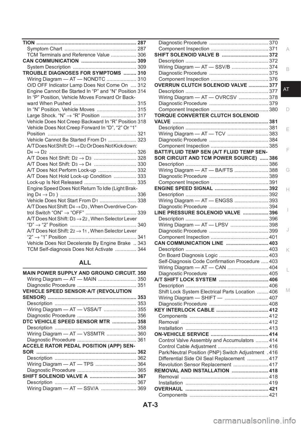
AT-3
D
E
F
G
H
I
J
K
L
MA
B
AT TION ........................................................................ 287
Symptom Chart .................................................... 287
TCM Terminals and Reference Value ................... 306
CAN COMMUNICATION ........................................ 309
System Description .............................................. 309
TROUBLE DIAGNOSES FOR SYMPTOMS .......... 310
Wiring Diagram — AT — NONDTC ...................... 310
O/D OFF Indicator Lamp Does Not Come On ..... 312
Engine Cannot Be Started In “P” and “N” Position . 314
In “P” Position, Vehicle Moves Forward Or Back-
ward When Pushed .............................................. 315
In “N” Position, Vehicle Moves ............................. 315
Large Shock. “N” → “R” Position .......................... 317
Vehicle Does Not Creep Backward In “R” Position . 318
Vehicle Does Not Creep Forward In “D”, “2” Or “1”
Position ................................................................ 321
Vehicle Cannot Be Started From D
1 ..................... 323
A/T Does Not Shift: D
1→ D2 Or Does Not Kick down:
D
4→ D2 ............................................................... 326
A/T Does Not Shift: D
2→ D3 ............................... 328
A/T Does Not Shift: D
3→ D4 ............................... 330
A/T Does Not Perform Lock-up ............................ 332
A/T Does Not Hold Lock-up Condition ................. 333
Lock-up Is Not Released ...................................... 335
Engine Speed Does Not Return To Idle (Light Brak-
ing D
4→ D3 ) ....................................................... 336
Vehicle Does Not Start From D
1 ........................... 338
A/T Does Not Shift: D
4→ D3 , When Overdrive Con-
trol Switch “ON” → “OFF” ..................................... 339
A/T Does Not Shift: D
3→ 22 , W h e n S e l e c t o r L e v e r
“D”→ “2” Position ................................................ 340
A/T Does Not Shift: 2
2→ 11 , W h e n S e l e c t o r L e v e r
“2” → “1” Position ................................................. 341
Vehicle Does Not Decelerate By Engine Brake ... 343
TCM Self-diagnosis Does Not Activate ................ 344
ALL
MAIN POWER SUPPLY AND GROUND CIRCUIT . 350
Wiring Diagram — AT — MAIN ............................ 350
Diagnostic Procedure ........................................... 351
VEHICLE SPEED SENSOR·A/T (REVOLUTION
SENSOR) ................................................................ 353
Description ........................................................... 353
Wiring Diagram — AT — VSSA/T ........................ 355
Diagnostic Procedure ........................................... 356
DTC VEHICLE SPEED SENSOR MTR .................. 358
Description ........................................................... 358
Wiring Diagram — AT — VSSMTR ...................... 360
Diagnostic Procedure ........................................... 361
ACCELE RATOR PEDAL POSITION (APP) SEN-
SOR ........................................................................ 362
Description ........................................................... 362
Wiring Diagram — AT — TPS .............................. 364
Diagnostic Procedure ........................................... 365
SHIFT SOLENOID VALVE A .................................. 367
Description ........................................................... 367
Wiring Diagram — AT — SSV/A .......................... 369Diagnostic Procedure ...........................................370
Component Inspection ..........................................371
SHIFT SOLENOID VALVE B ..................................372
Description ............................................................372
Wiring Diagram — AT — SSV/B ...........................374
Diagnostic Procedure ...........................................375
Component Inspection ..........................................376
OVERRUN CLUTCH SOLENOID VALVE ...............377
Description ............................................................377
Wiring Diagram — AT — OVRCSV ......................378
Diagnostic Procedure ...........................................379
Component Inspection ..........................................380
TORQUE CONVERTER CLUTCH SOLENOID
VALVE .....................................................................381
Description ............................................................381
Wiring Diagram — AT — TCV ..............................383
Diagnostic Procedure ...........................................384
Component Inspection ..........................................385
BATT/FLUID TEMP SEN (A/T FLUID TEMP SEN-
SOR CIRCUIT AND TCM POWER SOURCE) .......386
Description ............................................................386
Wiring Diagram — AT — BA/FTS .........................388
Diagnostic Procedure ...........................................389
Component Inspection ..........................................391
ENGINE SPEED SIGNAL .......................................392
Description ............................................................392
Wiring Diagram — AT — ENGSS .........................393
Diagnostic Procedure ...........................................394
LINE PRESSURE SOLENOID VALVE ..................
.396
Description ............................................................396
Wiring Diagram — AT — LPSV ............................398
Diagnostic Procedure ...........................................399
Component Inspection ..........................................401
CAN COMMUNICATION LINE ...............................403
Description ............................................................403
On Board Diagnosis Logic ....................................403
Self-Diagnosis Code Confirmation Procedure ......403
Wiring Diagram — AT — CAN ..............................404
Diagnostic Procedure ...........................................405
A/T SHIFT LOCK SYSTEM ....................................406
Description ............................................................406
Shift Lock System Electrical Parts Location .........406
Wiring Diagram — SHIFT — ................................407
Diagnostic Procedure ...........................................408
KEY INTERLOCK CABLE ......................................412
Components .........................................................412
Removal ...............................................................412
Installation ............................................................413
ON-VEHICLE SERVICE ..........................................414
Control Valve Assembly and Accumulators ..........414
Control Cable Adjustment .....................................416
Park/Neutral Position (PNP) Switch Adjustment ..416
Differential Side Oil Seal Replacement ................417
Revolution Sensor Replacement ..........................417
REMOVAL AND INSTALLATION ...........................418
Removal ...............................................................418
Installation ............................................................419
OVERHAUL ............................................................421
Components .........................................................421
Page 2086 of 3833
AT-8
PRECAUTIONS
●Converter is contaminated with engine coolant containing antifreeze.
●Internal failure of stator roller clutch.
●Heavy clutch debris due to overheating (blue converter).
●Steel particles or clutch lining material found in fluid filter or on magnet when no internal parts in unit are
worn or damaged — indicates that lining material came from converter.
The torque converter should not be replaced if:
●The fluid has an odor, is discolored, and there is no evidence of metal or clutch facing particles.
●The threads in one or more of the converter bolt holes are damaged.
●Transaxle failure did not display evidence of damaged or worn internal parts, steel particles or clutch plate
lining material in unit and inside the fluid filter.
●Vehicle has been exposed to high mileage (only). The exception may be where the torque converter
clutch dampener plate lining has seen excess wear by vehicles operated in heavy and/or constant traffic,
such as taxi, delivery or police use.
EURO-OBD SELF-DIAGNOSIS — EURO-OBD —
●A/T self-diagnosis is performed by the TCM in combination with the ECM. The results can be read through
the blinking pattern of the O/D OFF indicator lamp or the malfunction indicator lamp (MIL). Refer to the
table on AT- 4 2 , "
SELF-DIAGNOSTIC RESULT TEST MODE" for the indicator used to display each self-
diagnostic result.
●The self-diagnostic results indicated by the MIL are automatically stored in both the ECM and TCM mem-
ories.
Always perform the procedure “HOW TO ERASE DTC” on AT- 3 9 , "
HOW TO ERASE DTC" to com-
plete the repair and avoid unnecessary blinking of the MIL.
●The following self-diagnostic items can be detected using ECM self-diagnostic results mode* only when
the O/D OFF indicator lamp does not indicate any malfunctions.
–PNP switch
–A/T 1st, 2nd, 3rd, or 4th gear function
*: For details of EURO-OBD, refer to EC-44, "
ON BOARD DIAGNOSTIC (OBD) SYSTEM" (QR25DE) or EC-
777, "ON BOARD DIAGNOSTIC (OBD) SYSTEM" (QR20DE).
●Certain systems and components, especially those related to EURO-OBD, may use a new style
slide-locking type harness connector.
For description and how to disconnect, refer to PG-68, "
HARNESS CONNECTOR" .
Wiring Diagrams and Trouble DiagnosisECS004Q4
When you read wiring diagrams, refer to the following:
●GI-13, "How to Read Wiring Diagrams"
●PG-2, "POWER SUPPLY ROUTING"
When you perform trouble diagnosis, refer to the following:
●GI-10, "HOW TO FOLLOW TEST GROUPS IN TROUBLE DIAGNOSES"
●GI-23, "How to Perform Efficient Diagnosis for an Electrical Incident"
Page 2093 of 3833
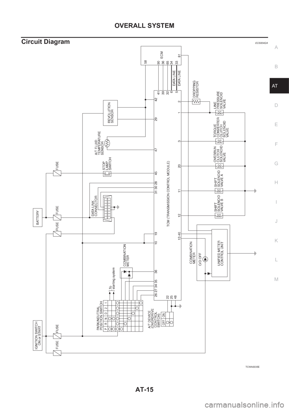
OVERALL SYSTEM
AT-15
D
E
F
G
H
I
J
K
L
MA
B
AT
Circuit DiagramECS004QA
TCWA0035E
Page 2187 of 3833
![NISSAN X-TRAIL 2001 Service Repair Manual CAN COMMUNICATION
AT-109
[EURO-OBD]
D
E
F
G
H
I
J
K
L
MA
B
AT
CAN COMMUNICATIONPFP:23710
System DescriptionECS004VP
CAN (Controller Area Network) is a serial communication line for real time applicati NISSAN X-TRAIL 2001 Service Repair Manual CAN COMMUNICATION
AT-109
[EURO-OBD]
D
E
F
G
H
I
J
K
L
MA
B
AT
CAN COMMUNICATIONPFP:23710
System DescriptionECS004VP
CAN (Controller Area Network) is a serial communication line for real time applicati](/manual-img/5/57405/w960_57405-2186.png)
CAN COMMUNICATION
AT-109
[EURO-OBD]
D
E
F
G
H
I
J
K
L
MA
B
AT
CAN COMMUNICATIONPFP:23710
System DescriptionECS004VP
CAN (Controller Area Network) is a serial communication line for real time application. It is an on-vehicle mul-
tiplex communication line with high data communication speed and excellent error detection ability. Many elec-
tronic control units are equipped onto a vehicle, and each control unit shares information and links with other
control units during operation (not independent). In CAN communication, control units are connected with 2
communication lines (CAN H line, CAN L line) allowing a high rate of information transmission with less wiring.
Each control unit transmits/receives data but selectively reads required data only.
FOR A/T MODELS
System diagram
Input/output signal chart
T: Transmit R: Receive
SKIA0884E
Signals ECM TCM
Engine coolant temperature signal T R
Accelerator pedal position signal T R
A/T self-diagnosis signal R T
Page 2190 of 3833
![NISSAN X-TRAIL 2001 Service Repair Manual AT-112
[EURO-OBD]
DTC P0705 PARK/NEUTRAL POSITION (PNP) SWITCH
Wiring Diagram — AT — PNP/SW
ECS004QX
TCWA0047E NISSAN X-TRAIL 2001 Service Repair Manual AT-112
[EURO-OBD]
DTC P0705 PARK/NEUTRAL POSITION (PNP) SWITCH
Wiring Diagram — AT — PNP/SW
ECS004QX
TCWA0047E](/manual-img/5/57405/w960_57405-2189.png)
AT-112
[EURO-OBD]
DTC P0705 PARK/NEUTRAL POSITION (PNP) SWITCH
Wiring Diagram — AT — PNP/SW
ECS004QX
TCWA0047E
Page 2196 of 3833
![NISSAN X-TRAIL 2001 Service Repair Manual AT-118
[EURO-OBD]
DTC P0710 A/T FLUID TEMPERATURE SENSOR CIRCUIT
Wiring Diagram — AT — FTS
ECS004R1
TCWA0048E NISSAN X-TRAIL 2001 Service Repair Manual AT-118
[EURO-OBD]
DTC P0710 A/T FLUID TEMPERATURE SENSOR CIRCUIT
Wiring Diagram — AT — FTS
ECS004R1
TCWA0048E](/manual-img/5/57405/w960_57405-2195.png)
AT-118
[EURO-OBD]
DTC P0710 A/T FLUID TEMPERATURE SENSOR CIRCUIT
Wiring Diagram — AT — FTS
ECS004R1
TCWA0048E