2001 NISSAN X-TRAIL warning
[x] Cancel search: warningPage 338 of 3833
CO-32
[YD22DDTi]
RADIATOR
RADIATOR
PFP:21400
Removal and InstallationEBS00BB0
WARNING:
Never remove the radiator cap when the engine is hot. Serious burns could occur from high pressure
engine coolant escaping from the radiator. Wrap a thick cloth around the cap. Slowly turn it a quarter
turn to allow built-up pressure to escape. Carefully remove the cap by turning it all the way.
REMOVAL
1. Drain engine coolant. Refer to CO-29, "DRAINING ENGINE COOLANT" .
2. Remove undercover.
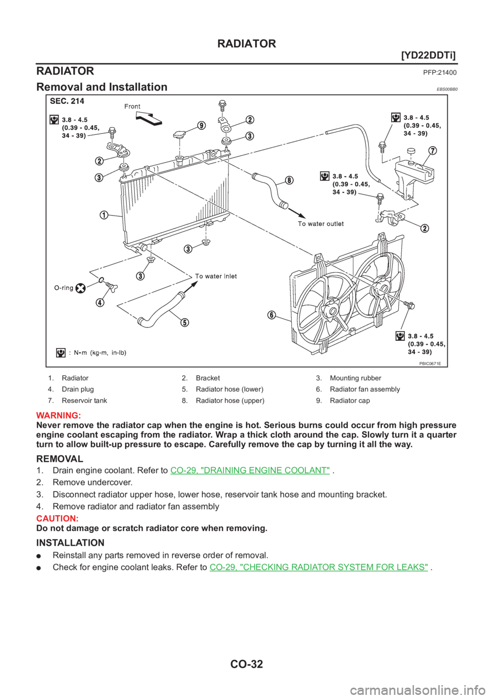
3. Disconnect radiator upper hose, lower hose, reservoir tank hose and mounting bracket.
4. Remove radiator and radiator fan assembly
CAUTION:
Do not damage or scratch radiator core when removing.
INSTALLATION
●Reinstall any parts removed in reverse order of removal.
●Check for engine coolant leaks. Refer to CO-29, "CHECKING RADIATOR SYSTEM FOR LEAKS" .
PBIC0671E
1. Radiator 2. Bracket 3. Mounting rubber
4. Drain plug 5. Radiator hose (lower) 6. Radiator fan assembly
7. Reservoir tank 8. Radiator hose (upper) 9. Radiator cap
Page 344 of 3833
CO-38
[YD22DDTi]
RADIATOR (ALUMINUM TYPE)
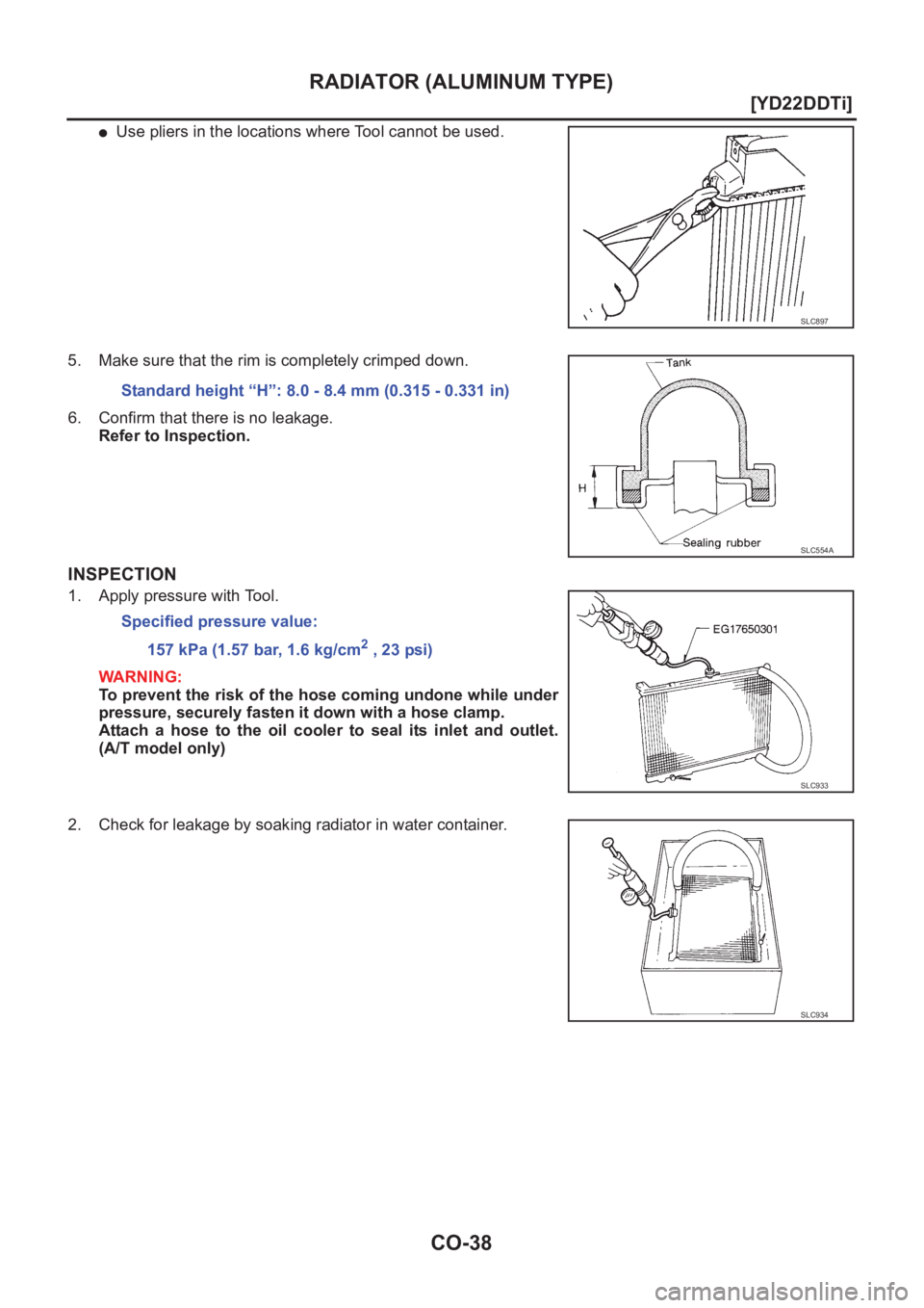
●Use pliers in the locations where Tool cannot be used.
5. Make sure that the rim is completely crimped down.
6. Confirm that there is no leakage.
Refer to Inspection.
INSPECTION
1. Apply pressure with Tool.
WARNING:
To prevent the risk of the hose coming undone while under
pressure, securely fasten it down with a hose clamp.
Attach a hose to the oil cooler to seal its inlet and outlet.
(A/T model only)
2. Check for leakage by soaking radiator in water container.
SLC897
Standard height “H”: 8.0 - 8.4 mm (0.315 - 0.331 in)
SLC554A
Specified pressure value:
157 kPa (1.57 bar, 1.6 kg/cm
2 , 23 psi)
SLC933
SLC934
Page 345 of 3833
WATER PUMP
CO-39
[YD22DDTi]
C
D
E
F
G
H
I
J
K
L
MA
CO
WAT E R P U MPPFP:21020
Removal and InstallationEBS00BB4
WARNING:
Never remove the radiator cap when the engine is hot. Serious burns could occur from high pressure
engine coolant escaping from the radiator.
REMOVAL
1. Remove the under cover, splash cover (right), and drive belt.
2. Drain engine coolant. Refer to CO-29, "
DRAINING ENGINE COOLANT" .
CAUTION:
Perform when the engine is cold.
3. Support the bottom of the oil pan with a floor jack etc, and remove the right engine mount bracket (front
side of the engine).
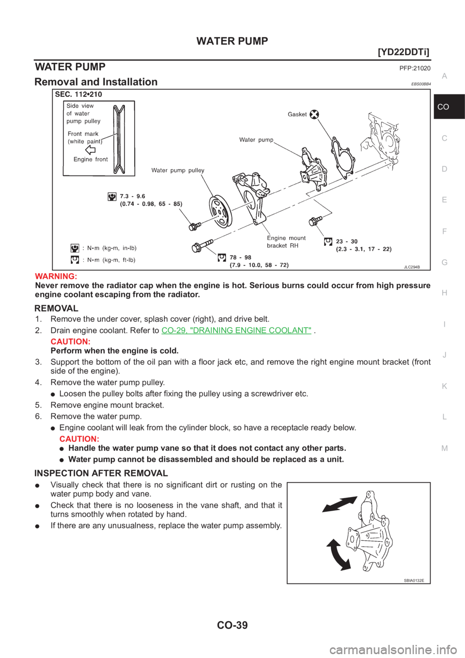
4. Remove the water pump pulley.
●Loosen the pulley bolts after fixing the pulley using a screwdriver etc.
5. Remove engine mount bracket.
6. Remove the water pump.
●Engine coolant will leak from the cylinder block, so have a receptacle ready below.
CAUTION:
●Handle the water pump vane so that it does not contact any other parts.
●Water pump cannot be disassembled and should be replaced as a unit.
INSPECTION AFTER REMOVAL
●Visually check that there is no significant dirt or rusting on the
water pump body and vane.
●Check that there is no looseness in the vane shaft, and that it
turns smoothly when rotated by hand.
●If there are any unusualness, replace the water pump assembly.
JLC294B
SBIA0132E
Page 347 of 3833
THERMOSTAT AND WATER PIPING
CO-41
[YD22DDTi]
C
D
E
F
G
H
I
J
K
L
MA
CO
THERMOSTAT AND WATER PIPINGPFP:21200
Removal and InstallationEBS00BK9
WARNING:
Never remove the radiator cap when the engine is hot. Serious burns could occur from high pressure
engine coolant escaping from the radiator.
REMOVAL
1. Remove the engine undercover and splash cover (right and left).
2. Drain engine coolant. Refer to CO-29, "
DRAINING ENGINE COOLANT" .
CAUTION:
Perform when the engine cold.
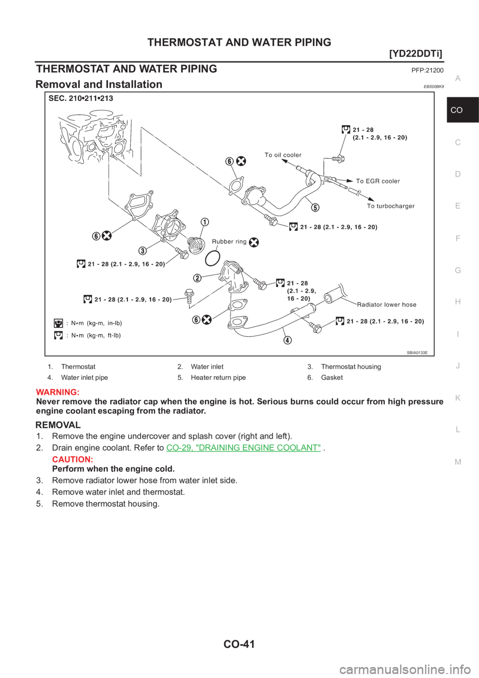
3. Remove radiator lower hose from water inlet side.
4. Remove water inlet and thermostat.
5. Remove thermostat housing.
SBIA0133E
1. Thermostat 2. Water inlet 3. Thermostat housing
4. Water inlet pipe 5. Heater return pipe 6. Gasket
Page 375 of 3833
PRECAUTIONS
EC-25
[QR25(WITH EURO-OBD)]
C
D
E
F
G
H
I
J
K
L
MA
EC
PRECAUTIONSPFP:00001
Precautions for Supplemental Restraint System (SRS) “AIR BAG” and “SEAT
BELT PRE-TENSIONER”
EBS00NBQ
The Supplemental Restraint System such as “AIR BAG” and “SEAT BELT PRE-TENSIONER”, used along
with a front seat belt, helps to reduce the risk or severity of injury to the driver and front passenger for certain
types of collision. Information necessary to service the system safely is included in the SRS and SB section of
this Service Manual.
WARNING:
●To avoid rendering the SRS inoperative, which could increase the risk of personal injury or death
in the event of a collision which would result in air bag inflation, all maintenance must be per-
formed by an authorized NISSAN/INFINITI dealer.
●Improper maintenance, including incorrect removal and installation of the SRS, can lead to per-
sonal injury caused by unintentional activation of the system. For removal of Spiral Cable and Air
Bag Module, see the SRS section.
●Do not use electrical test equipment on any circuit related to the SRS unless instructed to in this
Service Manual. SRS wiring harnesses can be identified by yellow and/or orange harness connec-
tors.
On Board Diagnostic (OBD) System of Engine and A/TEBS00M04
The ECM has an on board diagnostic system. It will light up the malfunction indicator (MI) to warn the driver of
a malfunction causing emission deterioration.
CAUTION:
●Be sure to turn the ignition switch OFF and disconnect the negative battery terminal before any
repair or inspection work. The open/short circuit of related switches, sensors, solenoid valves,
etc. will cause the MI to light up.
●Be sure to connect and lock the connectors securely after work. A loose (unlocked) connector will
cause the MI to light up due to the open circuit. (Be sure the connector is free from water, grease,
dirt, bent terminals, etc.)
●Certain systems and components, especially those related to OBD, may use a new style slide-
locking type harness connector. For description and how to disconnect, refer to PG-68, "
HAR-
NESS CONNECTOR" .
●Be sure to route and secure the harnesses properly after work. The interference of the harness
with a bracket, etc. may cause the MI to light up due to the short circuit.
●Be sure to connect rubber tubes properly after work. A misconnected or disconnected rubber tube
may cause the MI to light up due to the malfunction of the fuel injection system, etc.
●Be sure to erase the unnecessary malfunction information (repairs completed) from the ECM and
TCM (Transmission control module) before returning the vehicle to the customer.
PrecautionEBS00M05
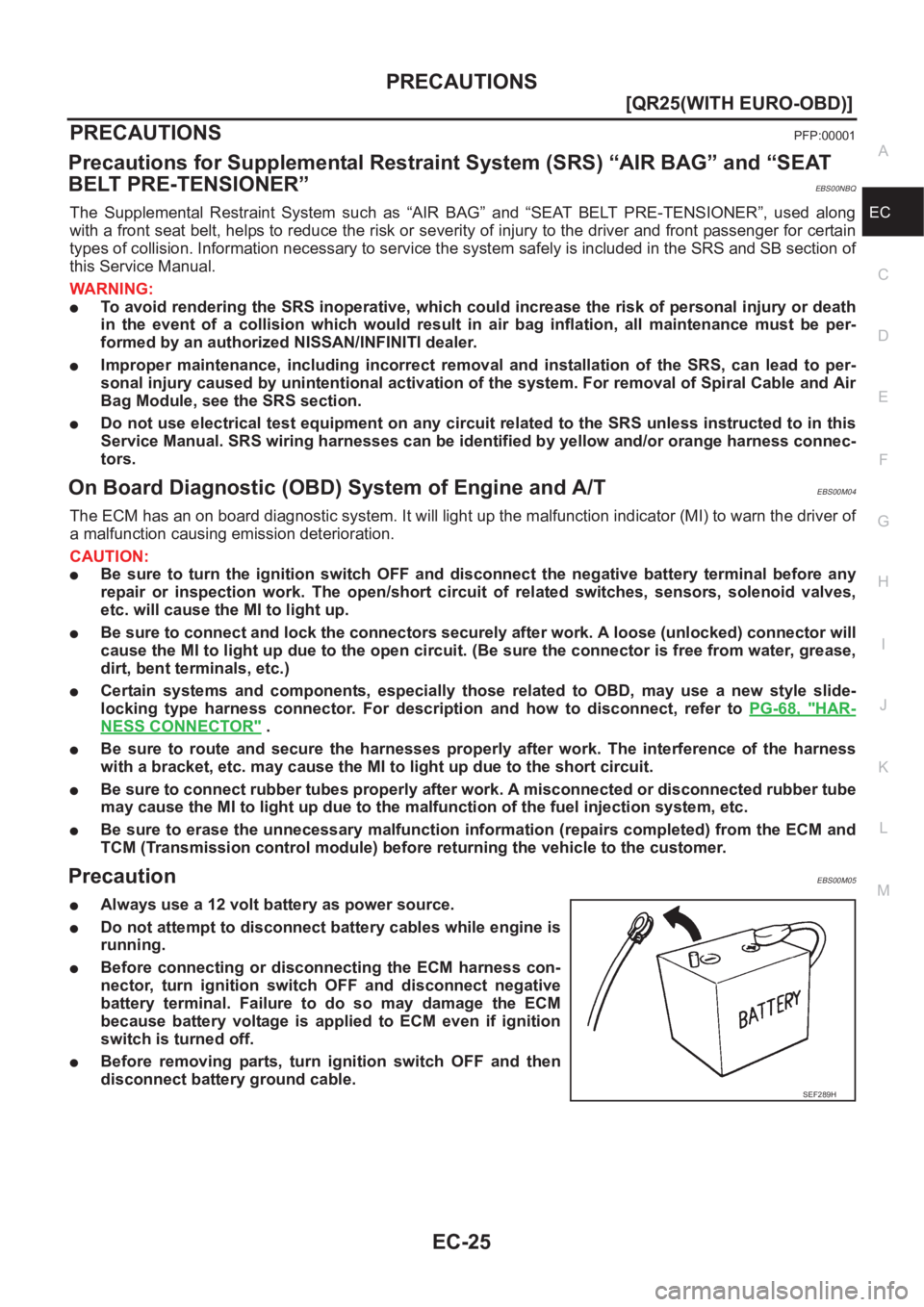
●Always use a 12 volt battery as power source.
●Do not attempt to disconnect battery cables while engine is
running.
●Before connecting or disconnecting the ECM harness con-
nector, turn ignition switch OFF and disconnect negative
battery terminal. Failure to do so may damage the ECM
because battery voltage is applied to ECM even if ignition
switch is turned off.
●Before removing parts, turn ignition switch OFF and then
disconnect battery ground cable.
SEF289H
Page 408 of 3833
EC-58
[QR25(WITH EURO-OBD)]
ON BOARD DIAGNOSTIC (OBD) SYSTEM
5. System readiness test (SRT) codes
6. Test values
7. Others
Actual work procedures are explained using a DTC as an example. Be careful so that not only the DTC, but all
of the data listed above, are cleared from the ECM memory during work procedures.
NATS (Nissan Anti-theft System)EBS00M0P
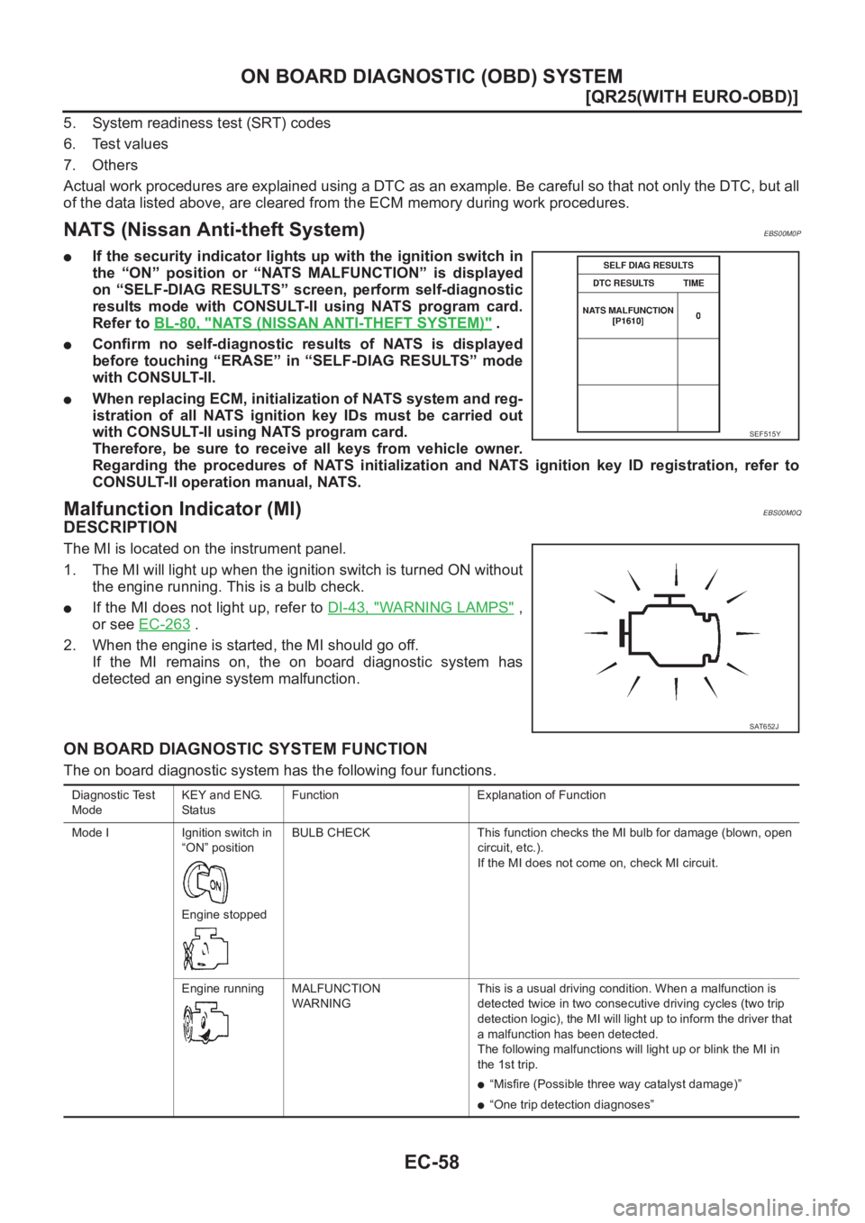
●If the security indicator lights up with the ignition switch in
the “ON” position or “NATS MALFUNCTION” is displayed
on “SELF-DIAG RESULTS” screen, perform self-diagnostic
results mode with CONSULT-II using NATS program card.
Refer to BL-80, "
NATS (NISSAN ANTI-THEFT SYSTEM)" .
●Confirm no self-diagnostic results of NATS is displayed
before touching “ERASE” in “SELF-DIAG RESULTS” mode
with CONSULT-II.
●When replacing ECM, initialization of NATS system and reg-
istration of all NATS ignition key IDs must be carried out
with CONSULT-II using NATS program card.
Therefore, be sure to receive all keys from vehicle owner.
Regarding the procedures of NATS initialization and NATS ignition key ID registration, refer to
CONSULT-II operation manual, NATS.
Malfunction Indicator (MI)EBS00M0Q
DESCRIPTION
The MI is located on the instrument panel.
1. The MI will light up when the ignition switch is turned ON without
the engine running. This is a bulb check.
●If the MI does not light up, refer to DI-43, "WARNING LAMPS" ,
or see EC-263
.
2. When the engine is started, the MI should go off.
If the MI remains on, the on board diagnostic system has
detected an engine system malfunction.
ON BOARD DIAGNOSTIC SYSTEM FUNCTION
The on board diagnostic system has the following four functions.
SEF515Y
SAT652J
Diagnostic Test
ModeKEY and ENG.
Sta tusFunction Explanation of Function
Mode I Ignition switch in
“ON” position
Engine stoppedBULB CHECK This function checks the MI bulb for damage (blown, open
circuit, etc.).
If the MI does not come on, check MI circuit.
Engine running MALFUNCTION
WARNINGThis is a usual driving condition. When a malfunction is
detected twice in two consecutive driving cycles (two trip
detection logic), the MI will light up to inform the driver that
a malfunction has been detected.
The following malfunctions will light up or blink the MI in
the 1st trip.
●“Misfire (Possible three way catalyst damage)”
●“One trip detection diagnoses”
Page 410 of 3833

EC-60
[QR25(WITH EURO-OBD)]
ON BOARD DIAGNOSTIC (OBD) SYSTEM
ECM has entered to Diagnostic Test Mode II (Self-diagnostic results).
How to Set Diagnostic Test Mode II (Heated Oxygen Sensor 1 Monitor)
1. Set the ECM in Diagnostic Test Mode II (Self-diagnostic results). Refer to EC-59, "How to Set Diagnostic
Test Mode II (Self-diagnostic Results)" .
2. Start Engine.
ECM has entered to Diagnostic Test Mode II (Heated oxygen sensor 1 monitor).
How to Erase Diagnostic Test Mode II (Self-diagnostic Results)
1. Set ECM in Diagnostic Test Mode II (Self-diagnostic results). Refer to EC-59, "How to Set Diagnostic Test
Mode II (Self-diagnostic Results)" .
2. Fully depress the accelerator pedal and keep it for more than 10 seconds.
The emission-related diagnostic information has been erased from the backup memory in the ECM.
3. Fully release the accelerator pedal, and confirm the DTC 0000 is displayed.
DIAGNOSTIC TEST MODE I — BULB CHECK
In this mode, the MI on the instrument panel should stay ON. If it remains OFF, check the bulb. Refer to DI-43,
"WARNING LAMPS" or see EC-263 .
DIAGNOSTIC TEST MODE I — MALFUNCTION WARNING
●These DTC numbers are clarified in Diagnostic Test Mode II (SELF-DIAGNOSTIC RESULTS)
DIAGNOSTIC TEST MODE II — SELF-DIAGNOSTIC RESULTS
In this mode, the DTC and 1st trip DTC are indicated by the number of blinks of the MI as shown below.
The DTC and 1st trip DTC are displayed at the same time. If the MI does not illuminate in diagnostic test mode
I (Malfunction warning), all displayed items are 1st trip DTCs. If only one code is displayed when the MI illumi-
nates in diagnostic test mode II (SELF-DIAGNOSTIC RESULTS), it is a DTC; if two or more codes are dis-
played, they may be either DTCs or 1st trip DTCs. DTC No. is same as that of 1st trip DTC. These unidentified
PBIB0092E
MI Condition
ON When the malfunction is detected or the ECM's CPU is malfunctioning.
OFF No malfunction.
Page 675 of 3833
DTC P1217 ENGINE OVER TEMPERATURE
EC-325
[QR25(WITH EURO-OBD)]
C
D
E
F
G
H
I
J
K
L
MA
EC
Overall Function CheckEBS00M93
Use this procedure to check the overall function of the cooling fan. During this check, a DTC might not be con-
firmed.
WARNING:
Never remove the radiator cap when the engine is hot. Serious burns could be caused by high pres-
sure fluid escaping from the radiator.
Wrap a thick cloth around cap. Carefully remove the cap by turning it a quarter turn to allow built-up
pressure to escape. Then turn the cap all the way off.
WITH CONSULT-II
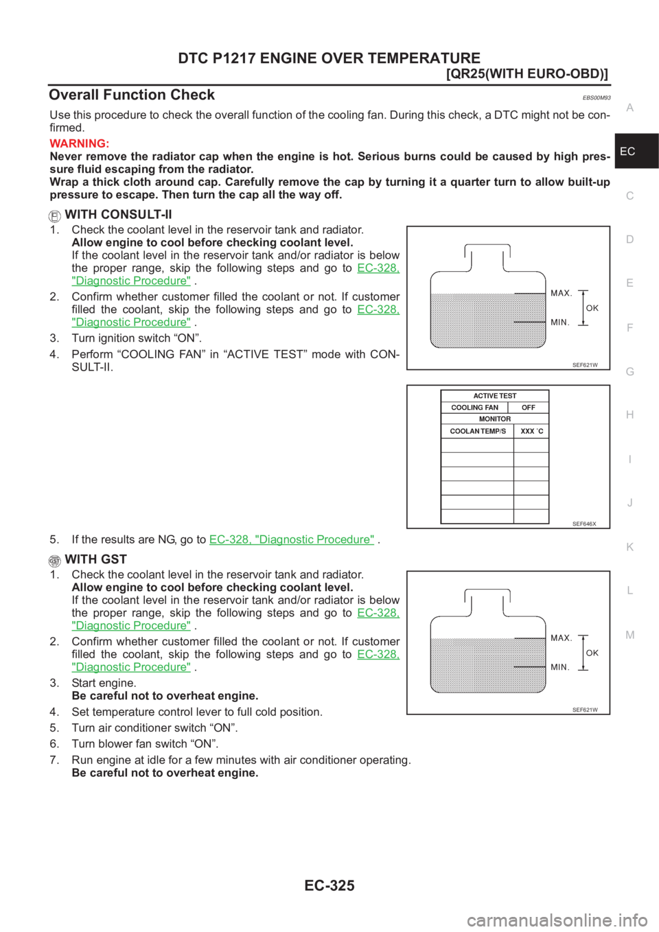
1. Check the coolant level in the reservoir tank and radiator.
Allow engine to cool before checking coolant level.
If the coolant level in the reservoir tank and/or radiator is below
the proper range, skip the following steps and go to EC-328,
"Diagnostic Procedure" .
2. Confirm whether customer filled the coolant or not. If customer
filled the coolant, skip the following steps and go to EC-328,
"Diagnostic Procedure" .
3. Turn ignition switch “ON”.
4. Perform “COOLING FAN” in “ACTIVE TEST” mode with CON-
SULT-II.
5. If the results are NG, go to EC-328, "
Diagnostic Procedure" .
WITH GST
1. Check the coolant level in the reservoir tank and radiator.
Allow engine to cool before checking coolant level.
If the coolant level in the reservoir tank and/or radiator is below
the proper range, skip the following steps and go to EC-328,
"Diagnostic Procedure" .
2. Confirm whether customer filled the coolant or not. If customer
filled the coolant, skip the following steps and go to EC-328,
"Diagnostic Procedure" .
3. Start engine.
Be careful not to overheat engine.
4. Set temperature control lever to full cold position.
5. Turn air conditioner switch “ON”.
6. Turn blower fan switch “ON”.
7. Run engine at idle for a few minutes with air conditioner operating.
Be careful not to overheat engine.
SEF621W
SEF646X
SEF621W