2001 NISSAN X-TRAIL oil temperature
[x] Cancel search: oil temperaturePage 280 of 3833
![NISSAN X-TRAIL 2001 Service Repair Manual EM-230
[YD22DDTi]
SERVICE DATA AND SPECIFICATIONS (SDS)
Common rail51.0 - 64.0 (5.2 - 6.5, 38 - 47)
Fuel supply pump51.0 - 56.0 (5.2 - 5.7, 38 - 41)
Fuel supply pump sprocket 37.0 - 41.0 (3.8 - 4.2, 2](/manual-img/5/57405/w960_57405-279.png "NISSAN X-TRAIL 2001 Service Repair Manual EM-230
[YD22DDTi]
SERVICE DATA AND SPECIFICATIONS (SDS)
Common rail51.0 - 64.0 (5.2 - 6.5, 38 - 47)
Fuel supply pump51.0 - 56.0 (5.2 - 5.7, 38 - 41)
Fuel supply pump sprocket 37.0 - 41.0 (3.8 - 4.2, 2")
EM-230
[YD22DDTi]
SERVICE DATA AND SPECIFICATIONS (SDS)
Common rail51.0 - 64.0 (5.2 - 6.5, 38 - 47)
Fuel supply pump51.0 - 56.0 (5.2 - 5.7, 38 - 41)
Fuel supply pump sprocket 37.0 - 41.0 (3.8 - 4.2, 28 - 30)
Fuel supply pump rear bracket 27.0 - 37.0 (2.8 - 3.8, 20 - 27)
Front chain case
6.9 - 8.8 (0.7 - 0.9, 61 - 78)*
2
Chain tensioner
8.5 - 10.7 (0.86 - 1.1, 75 - 95)*2
Tension guide21.0 - 26.0 (2.1 - 2.7, 16 - 19)
Slack guide21.0 - 26.0 (2.1 - 2.7, 16 - 19)
Camshaft sprocket 138 - 147 (14.0 - 15.0, 102 - 108)
Fuel supply pump sprocket 38.0 - 41.0 (3.8 - 4.2, 28 - 30)
Oil pump12.0 - 13.0 (1.3 - 1.4, 9 - 10)
Power steering pump51.0 - 56.0 (5.2 - 5.8, 38 - 41)
Rear chain case12.0 - 13.0 (1.2 - 1.4, 19 - 10)
Engine coolant temperature sensor 12.0 - 15.0 (1.2 - 1.6, 9 - 11)
*1 Cylinder head 1) 29 - 38 (2.9 - 3.9, 21 - 28)
2) 180° to 185°
3) 0 (0, 0)
4) 35 to 44 (3.5 - 4.5, 26 - 32)
5) 90° to 95°(angle tightening)
6) 90° to 95° (angle tightening)
Water outlet21 - 28 (2.1 - 2.9, 16 - 20)
Glow plug18.0 - 21.0 (1.8 - 2.2, 13 - 15)
*1 Flywheel103 - 112 (10.5 - 11.5, 76 - 83)
Oil pressure switch13.0 - 17.0 (1.25 - 1.75, 9 - 12)
Oil jet6.1 - 10.7(0.62 - 1.1, 54 - 95)
Oil jet relief valve40 - 58 (4.0 - 6.0, 29 - 43)
Rear oil seal retainer12.0 - 13.0 (1.2 - 1.4, 9 - 10)
Page 287 of 3833
![NISSAN X-TRAIL 2001 Service Repair Manual ENGINE OIL
LU-7
[QR]
C
D
E
F
G
H
I
J
K
L
MA
LU
ENGINE OILPFP:KLA92
InspectionEBS00KO3
ENGINE OIL LEVEL
●Before starting the engine, put vehicle horizontally then check
the engine oil leve](/manual-img/5/57405/w960_57405-286.png "NISSAN X-TRAIL 2001 Service Repair Manual ENGINE OIL
LU-7
[QR]
C
D
E
F
G
H
I
J
K
L
MA
LU
ENGINE OILPFP:KLA92
InspectionEBS00KO3
ENGINE OIL LEVEL
●Before starting the engine, put vehicle horizontally then check
the engine oil leve")
ENGINE OIL
LU-7
[QR]
C
D
E
F
G
H
I
J
K
L
MA
LU
ENGINE OILPFP:KLA92
InspectionEBS00KO3
ENGINE OIL LEVEL
●Before starting the engine, put vehicle horizontally then check
the engine oil level. If the engine is already started, stop it and
allow 10 minutes before checking.
●Check that the engine oil level is within the range shown in the
figure.
●If it is out of range, adjust it.
ENGINE OIL APPEARANCE
●Check the engine oil for white turbidity or remarkable contamination.
●If the engine oil becomes turbid and white, it is highly probable that it is contaminated with engine coolant.
Find the cause and repair.
ENGINE OIL LEAKAGE
Check for engine oil leakage around the following area.
●Oil pan
●Oil pan drain plug
●Oil pressure switch
●Oil filter
●Oil cooler
●Intake valve timing control cover and intake valve timing control solenoid valve
●Front cover
●Mating surface between cylinder block and cylinder head
●Mating surface between cylinder head and rocker cover
●Crankshaft oil seal.
OIL PRESSURE CHECK
WARNING:
●Be careful not to burn yourself, as the engine oil is hot.
●Engine oil pressure check should be done in “ Parking
position” (A/T model) or “Neutral position” (M/T model).
1. Check engine oil level. Refer to LU-7, "
ENGINE OIL LEVEL" .
2. Remove the undercover.
3. Remove the oil pressure switch to connect the oil pressure
gauge.
4. After warming up the engine, check that oil pressure corre-
sponding to the engine speed is produced.
Engine oil pressure [Engine oil temperature at 80 °C (176 °F)]
5. After checking, install the oil pressure switch as follows.
a. Remove old sealant adhering to the switch and engine.
b. Apply thread sealant.
Use Genuine Liquid Gasket or equivalent.
PBIC0249E
KBIA0275E
Engine speed (rpm) Idle speed 2,000 6,000
Engine pressure
kPa (bar, kg/cm
2 , psi)Approx. 98 (0.98, 1.0, 14) or more Approx. 294 (2.9, 3.0, 43) or more Approx. 392 (3.9, 4.0, 57) or more
Page 288 of 3833
![NISSAN X-TRAIL 2001 Service Repair Manual LU-8
[QR]
ENGINE OIL
c. After warming up the engine, check for engine oil leakage with running engine.
Changing Engine OilEBS00KO4
WARNING:
●Be careful not to burn yourself, as the engine oil is hot](/manual-img/5/57405/w960_57405-287.png "NISSAN X-TRAIL 2001 Service Repair Manual LU-8
[QR]
ENGINE OIL
c. After warming up the engine, check for engine oil leakage with running engine.
Changing Engine OilEBS00KO4
WARNING:
●Be careful not to burn yourself, as the engine oil is hot")
LU-8
[QR]
ENGINE OIL
c. After warming up the engine, check for engine oil leakage with running engine.
Changing Engine OilEBS00KO4
WARNING:
●Be careful not to burn yourself, as the engine oil is hot.
●Prolonged and repeated contact with used engine oil may
cause skin cancer. Try to avoid direct skin contact with
used engine oil. If skin contact is made, wash thoroughly
with soap or hand cleaner as soon as possible.
1. Warm up engine, put vehicle horizontally and check for engine
oil leakage from engine components.
2. Stop engine and wait for 10 minutes.
3. Remove drain plug and oil filler cap.
4. Drain engine oil.
●Install drain plug and refill with new engine oil.
Engine oil specifications and viscosity:
●API grade SG, SH, SJ or SL.
●ILSAC grade GF-I, GF-II or GF-III
●ACEA 96-A2
●Refer to MA-16, "RECOMMENDED FLUIDS AND LUBRICANTS" for further detail.
Engine oil capacity (Approximate):
Unit: (lmp qt)
CAUTION:
●Be sure to clean drain plug and install with new washer.
●The refill capacity depends on the engine oil temperature and drain time. Use these specifica-
tions for reference only.
●Always use the dipstick to the determine when the proper amount of engine oil is in the engine.
5. Warm up engine and check area around drain plug and oil filter for engine oil leakage.
6. Stop engine and wait for 10 minutes.
7. Check engine oil level. Refer to LU-7, "
ENGINE OIL LEVEL" . Oil pressure switch:
: 12.3 - 17.2 N·m (1.25 - 1.75 kg-m, 9 - 12 ft-lb)
PBIC0250E
Drain and refillWith oil filter change Approximately 3.9 (3-3/8)
Without oil filter change Approximately 3.5 (3-1/8)
Dry engine (engine overhaul)Approximately 4.5 (4)
Oil pan drain plug:
: 29.4 - 39.2 N·m (3.0 - 4.0 kg-m, 22 - 28 ft-lb)
Page 294 of 3833
![NISSAN X-TRAIL 2001 Service Repair Manual LU-14
[QR]
SERVICE DATA AND SPECIFICATIONS (SDS)
SERVICE DATA AND SPECIFICATIONS (SDS)
PFP:00030
Standard and LimitEBS00KO9
OIL PRESSURE
*:Engine oil temperature at 80°C (176°C)
OIL PUMP
Unit: mm (i](/manual-img/5/57405/w960_57405-293.png "NISSAN X-TRAIL 2001 Service Repair Manual LU-14
[QR]
SERVICE DATA AND SPECIFICATIONS (SDS)
SERVICE DATA AND SPECIFICATIONS (SDS)
PFP:00030
Standard and LimitEBS00KO9
OIL PRESSURE
*:Engine oil temperature at 80°C (176°C)
OIL PUMP
Unit: mm (i")
LU-14
[QR]
SERVICE DATA AND SPECIFICATIONS (SDS)
SERVICE DATA AND SPECIFICATIONS (SDS)
PFP:00030
Standard and LimitEBS00KO9
OIL PRESSURE
*:Engine oil temperature at 80°C (176°C)
OIL PUMP
Unit: mm (in)
REGULATOR VALVE
Unit: mm (in)
ENGINE OIL CAPACITY
Unit: (Imp qt)
Tightening TorqueEBS00KOA
Unit: N·m (kg-m, ft-lb)
Unit: N·m (kg-m, in-lb)* Engine speed (rpm)
Approximate discharge pressure kPa (bar, kg/cm
2 , psi)*
Idle speed
2,000
6,000 More than 98 (0.98, 1.0, 14)
294 (2.9, 3.0, 43)
392 (3.9, 4.0, 57)
Body to outer rotor radial clearance 0.114 - 0.179 (0.0045 - 0.0070)
Inner rotor to outer rotor tip clearance Below 0.220 (0.0087)
Body to inner rotor axial clearance 0.030 - 0.070 (0.0012 - 0.0028)
Body to outer rotor axial clearance 0.060 - 0.110 (0.0024 - 0.0043)
Inner rotor to brazed portion of housing clearance 0.035 - 0.070 (0.0014 - 0.0028)
Regulator valve to oil pump cover clearance 0.040 - 0.097 (0.0016 - 0.0038)
With oil filter change Approximately 3.9 (3-3/8)
Without oil filter change Approximately 3.5 (3-1/8)
Dry engine (engine overhaul) Approximately 4.5 (4)
Oil pressure switch 12.3 - 17.2 (1.25 - 1.75, 9 - 12)
Oil pan drain plug 29.4 - 39.2 (3.0 - 4.0, 22 - 28)
Oil filter14.7 - 20.5 (1.5 - 2.1, 11 - 15)
Oil pump assembly 6.4 - 7.5 (0.66 - 0.76, 57 - 66)*
Oil pump cover 5.9 - 7.9 (0.60 - 0.81, 52 - 70)*
Regulator plug 39.2 - 68.6 (4.0 - 6.9, 29 - 50)
Oil cooler34.3 - 44.1 (3.5 - 4.4, 26 - 32)
Oil cooler bracket 19.6 - 23.5 (2.0 - 2.3, 15 - 17)
Page 298 of 3833
![NISSAN X-TRAIL 2001 Service Repair Manual LU-18
[YD22DDTi]
ENGINE OIL
ENGINE OIL
PFP:KLA92
InspectionEBS00B03
ENGINE OIL LEVEL AND MUDDINESS
●Before starting the engine, put vehicle horizontally then check
the engine oil level. If t](/manual-img/5/57405/w960_57405-297.png "NISSAN X-TRAIL 2001 Service Repair Manual LU-18
[YD22DDTi]
ENGINE OIL
ENGINE OIL
PFP:KLA92
InspectionEBS00B03
ENGINE OIL LEVEL AND MUDDINESS
●Before starting the engine, put vehicle horizontally then check
the engine oil level. If t")
LU-18
[YD22DDTi]
ENGINE OIL
ENGINE OIL
PFP:KLA92
InspectionEBS00B03
ENGINE OIL LEVEL AND MUDDINESS
●Before starting the engine, put vehicle horizontally then check
the engine oil level. If the engine is already started, stop it and
allow 10 minutes before checking.
●Check that the engine oil level is within the range shown in the
figure.
●If it is out of range, adjust it.
●Check the engine oil for white turbidity or remarkable contamina-
tion.
●If the engine oil becomes turbid and white, it is highly probable
that it is contaminated with engine coolant. Find the cause and
repair.
ENGINE OIL LEAKAGE
Check for engine oil leakage around the following area.
●Oil pan
●Oil pan drain plug
●Oil pressure switch
●Oil filter bracket
●Oil cooler.
●Oil pump housing
●Vacuum pump
●Cylinder head rear cover assembly
●Chain case
●Mating surface between cylinder block and cylinder head
●Mating surface between cylinder head and rocker cover
●Crankshaft oil seal. Refer to LU-18, "ENGINE OIL LEVEL AND MUDDINESS" .
ENGINE OIL PRESSURE CHECK
WARNING:
●Be careful not to burn yourself, as the engine oil is hot.
●Oil pressure check should be done in “ Neutral position”.
1. Check the engine oil level. Refer to LU-18, "
ENGINE OIL LEVEL
AND MUDDINESS" .
2. Remove the undercover.
3. Remove the oil pressure switch to connect the oil pressure
gauge.
4. After warming up the engine, check that oil pressure corre-
sponding to the engine speed is produced.
Engine oil pressure [Engine oil temperature at 80 °C (176 °F)]
5. After checking, install the oil pressure switch as follows.
a. Remove old sealant adhering to the switch and engine.
b. Apply thread sealant.
Use Genuine Liquid Gasket or equivalent.
SBIA0122E
SBIA0123E
Engine speed (rpm) Idle speed 2,000 4,000
Engine pressure
kPa (bar, kg/cm
2 , psi)Approx. 140 (1.40, 1.43, 20.3) or
moreApprox. 270 (2.69, 2.75, 39.1) or
moreApprox. 430 (4.29, 4.38, 62.3) or
more
Page 299 of 3833
![NISSAN X-TRAIL 2001 Service Repair Manual ENGINE OIL
LU-19
[YD22DDTi]
C
D
E
F
G
H
I
J
K
L
MA
LUc. After warming up the engine, check for oil leakage with running engine.
Changing Engine OilEBS00B04
WARNING:
●Be careful not to burn yourself,](/manual-img/5/57405/w960_57405-298.png "NISSAN X-TRAIL 2001 Service Repair Manual ENGINE OIL
LU-19
[YD22DDTi]
C
D
E
F
G
H
I
J
K
L
MA
LUc. After warming up the engine, check for oil leakage with running engine.
Changing Engine OilEBS00B04
WARNING:
●Be careful not to burn yourself,")
ENGINE OIL
LU-19
[YD22DDTi]
C
D
E
F
G
H
I
J
K
L
MA
LUc. After warming up the engine, check for oil leakage with running engine.
Changing Engine OilEBS00B04
WARNING:
●Be careful not to burn yourself, as the engine oil is hot.
●Prolonged and repeated contact with used engine oil may
cause skin cancer: try to avoid direct skin contact with
used engine oil. If skin contact is made, wash thoroughly
with soap or hand cleaner as soon as possible.
1. Warm up engine, put vehicle horizontally and check for engine
oil leakage from engine components.
2. Stop engine and wait for 10 minutes.
3. Remove drain plug and oil filler cap.
4. Drain engine oil.
●Install drain plug and refill with new engine oil.
Engine oil specification and viscosity:
●API grade CF-4.
●ACEA B1, B3, B4, B5
●Refer to MA-16, "RECOMMENDED FLUIDS AND LUBRI-
CANTS" .
Engine oil capacity (Approximate):
●The refill capacity depends on the engine oil temperature and drain time. Use these specifications for
reference only.
Always use the dipstick to the determine when the proper amount of engine oil is in the engine.
CAUTION:
●Be sure to clean drain plug and install with new washer.
●The refill capacity depends on the engine oil temperature and drain time. Use these specifica-
tions for reference only.
Always use the dipstick to the determine when the proper amount of engine oil is in the
engine.
5. Warm up engine and check area around drain plug and oil filter for engine oil leakage.
6. Stop engine and wait for 10 minutes.
7. Check engine oil level. Refer to LU-18, "
ENGINE OIL LEVEL AND MUDDINESS" . Oil pressure switch:
: 13.0 - 17.0 N·m (1.4 - 1.7 kg-m, 10 - 12 ft-lb)
PBIC0527E
Drain and refillWith oil filter change
5.2 (4-5/8 Imp qt)
Without oil filter change
4.9 (4-3/8 Imp qt)
Dry engine (engine overhaul)6.3 (5-1/2 Imp qt)
Oil pan drain plug:
: 29 - 39 N·m (3.0 - 4.0 kg-m, 22 - 29 ft-lb)
SBIA0122E
Page 369 of 3833
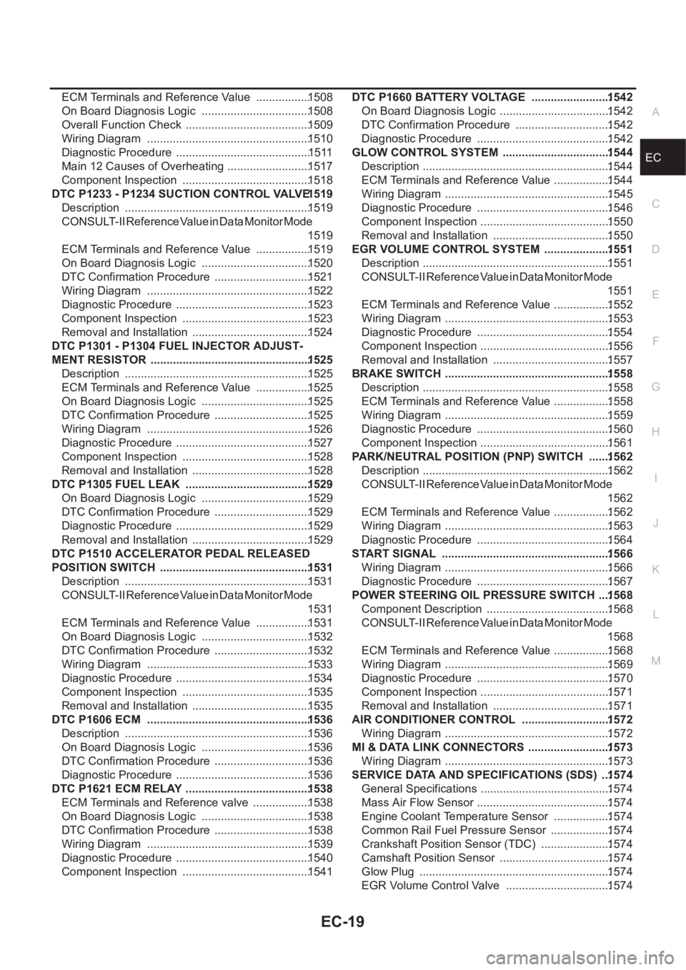
EC-19
C
D
E
F
G
H
I
J
K
L
M
ECA ECM Terminals and Reference Value .................1508
On Board Diagnosis Logic ..................................1508
Overall Function Check .......................................1509
Wiring Diagram ...................................................1510
Diagnostic Procedure ..........................................1511
Main 12 Causes of Overheating ..........................1517
Component Inspection ........................................1518
DTC P1233 - P1234 SUCTION CONTROL VALVE 1519
Description ..........................................................1519
CONSULT-II Reference Value in Data Monitor Mode
1519
ECM Terminals and Reference Value .................1519
On Board Diagnosis Logic ..................................1520
DTC Confirmation Procedure ..............................1521
Wiring Diagram ...................................................1522
Diagnostic Procedure ..........................................1523
Component Inspection ........................................1523
Removal and Installation .....................................1524
DTC P1301 - P1304 FUEL INJECTOR ADJUST-
MENT RESISTOR .................................................. 1525
Description ..........................................................1525
ECM Terminals and Reference Value .................1525
On Board Diagnosis Logic ..................................1525
DTC Confirmation Procedure ..............................1525
Wiring Diagram ...................................................1526
Diagnostic Procedure ..........................................1527
Component Inspection ........................................1528
Removal and Installation .....................................1528
DTC P1305 FUEL LEAK .......................................1529
On Board Diagnosis Logic ..................................1529
DTC Confirmation Procedure ..............................1529
Diagnostic Procedure ..........................................1529
Removal and Installation .....................................1529
DTC P1510 ACCELERATOR PEDAL RELEASED
POSITION SWITCH ...............................................1531
Description ..........................................................1531
CONSULT-II Reference Value in Data Monitor Mode
1531
ECM Terminals and Reference Value .................1531
On Board Diagnosis Logic ..................................1532
DTC Confirmation Procedure ..............................1532
Wiring Diagram ...................................................1533
Diagnostic Procedure ..........................................1534
Component Inspection ........................................1535
Removal and Installation .....................................1535
DTC P1606 ECM ...................................................1536
Description ..........................................................1536
On Board Diagnosis Logic ..................................1536
DTC Confirmation Procedure ..............................
1536
Diagnostic Procedure ..........................................1536
DTC P1621 ECM RELAY .......................................1538
ECM Terminals and Reference valve ..................1538
On Board Diagnosis Logic ..................................1538
DTC Confirmation Procedure ..............................1538
Wiring Diagram ...................................................1539
Diagnostic Procedure ..........................................1540
Component Inspection ........................................1541DTC P1660 BATTERY VOLTAGE .........................1542
On Board Diagnosis Logic ...................................1542
DTC Confirmation Procedure ..............................1542
Diagnostic Procedure ..........................................1542
GLOW CONTROL SYSTEM ..................................1544
Description ...........................................................1544
ECM Terminals and Reference Value ..................1544
Wiring Diagram ....................................................1545
Diagnostic Procedure ..........................................1546
Component Inspection .........................................1550
Removal and Installation .....................................1550
EGR VOLUME CONTROL SYSTEM .....................1551
Description ...........................................................1551
CONSULT-II Reference Value in Data Monitor Mode
1551
ECM Terminals and Reference Value ..................1552
Wiring Diagram ....................................................1553
Diagnostic Procedure ..........................................1554
Component Inspection .........................................1556
Removal and Installation .....................................1557
BRAKE SWITCH ....................................................1558
Description ...........................................................1558
ECM Terminals and Reference Value ..................1558
Wiring Diagram ....................................................1559
Diagnostic Procedure ..........................................1560
Component Inspection .........................................1561
PARK/NEUTRAL POSITION (PNP) SWITCH .......1562
Description ...........................................................1562
CONSULT-II Reference Value in Data Monitor Mode
1562
ECM Terminals and Reference Value ..................1562
Wiring Diagram ....................................................1563
Diagnostic Procedure ..........................................1564
START SIGNAL .....................................................1566
Wiring Diagram ....................................................1566
Diagnostic Procedure ..........................................1567
POWER STEERING OIL PRESSURE SWITCH ....1568
Component Description .......................................1568
CONSULT-II Reference Value in Data Monitor Mode
1568
ECM Terminals and Reference Value ..................1568
Wiring Diagram ....................................................1569
Diagnostic Procedure ..........................................1570
Component Inspection .........................................1571
Removal and Installation .....................................1571
AIR CONDITIONER CONTROL ............................1572
Wiring Diagram ....................................................1572
MI & DATA LINK CONNECTORS ..........................1573
Wiring Diagram ....................................................1573
SERVICE DATA AND SPECIFICATIONS (SDS) ...1574
General Specifications ......................................... 1574
Mass Air Flow Sensor ..........................................1574
Engine Coolant Temperature Sensor ..................1574
Common Rail Fuel Pressure Sensor ...................1574
Crankshaft Position Sensor (TDC) ......................1574
Camshaft Position Sensor ...................................1574
Glow Plug ............................................................1574
EGR Volume Control Valve .................................1574
Page 427 of 3833
![NISSAN X-TRAIL 2001 Service Repair Manual TROUBLE DIAGNOSIS
EC-77
[QR25(WITH EURO-OBD)]
C
D
E
F
G
H
I
J
K
L
MA
EC
16.CHECK TIMING CHAIN INSTALLATION
Check timing chain installation. Refer to EM-37, "
TIMING CHAIN" .
OK or NG
OK >> GO](/manual-img/5/57405/w960_57405-426.png "NISSAN X-TRAIL 2001 Service Repair Manual TROUBLE DIAGNOSIS
EC-77
[QR25(WITH EURO-OBD)]
C
D
E
F
G
H
I
J
K
L
MA
EC
16.CHECK TIMING CHAIN INSTALLATION
Check timing chain installation. Refer to EM-37, \"
TIMING CHAIN\" .
OK or NG
OK >> GO")
TROUBLE DIAGNOSIS
EC-77
[QR25(WITH EURO-OBD)]
C
D
E
F
G
H
I
J
K
L
MA
EC
16.CHECK TIMING CHAIN INSTALLATION
Check timing chain installation. Refer to EM-37, "
TIMING CHAIN" .
OK or NG
OK >> GO TO 17.
NG >> 1. Repair the timing chain installation.
2. GO TO 4.
17.DETECT MALFUNCTIONING PART
Check the following.
●Check camshaft position sensor (PHASE) and circuit. Refer to EC-233 .
●Check crankshaft position sensor (POS) and circuit. Refer to EC-227 .
OK or NG
OK >> GO TO 18.
NG >> 1. Repair or replace.
2. GO TO 4.
18.CHECK ECM FUNCTION
1. Substitute another known-good ECM to check ECM function. (ECM may be the cause of an incident, but
this is the rarely the case.)
2. Perform initialization of NATS system and registration of NATS ignition key IDs. Refer to EC-58, "
NATS
(Nissan Anti-theft System)" .
>> GO TO 4.
Symptom Matrix ChartEBS00M0W
SYSTEM — BASIC ENGINE CONTROL SYSTEM
SYMPTOM
Reference
page
HARD/NO START/RESTART (EXCP. HA)
ENGINE STALL
HESITATION/SURGING/FLAT SPOT
SPARK KNOCK/DETONATION
LACK OF POWER/POOR ACCELERATION
HIGH IDLE/LOW IDLE
ROUGH IDLE/HUNTING
IDLING VIBRATION
SLOW/NO RETURN TO IDLE
OVERHEATS/WATER TEMPERATURE HIGH
EXCESSIVE FUEL CONSUMPTION
EXCESSIVE OIL CONSUMPTION
BATTERY DEAD (UNDER CHARGE)
Warranty symptom code AA AB AC AD AE AF AG AH AJ AK AL AM HA
Fuel Fuel pump circuit 11232 22 3 2EC-405
Fuel pressure regulator system334444444 4EC-42
Injector circuit 11232 22 2EC-388
Evaporative emission system334444444 4EC-425