2001 NISSAN X-TRAIL gas type
[x] Cancel search: gas typePage 3277 of 3833

ATC-1
AUTOMATIC AIR CONDITIONER
J AIR CONDITIONER
CONTENTS
C
D
E
F
G
H
I
K
L
M
SECTION
A
B
AT C
AUTOMATIC AIR CONDITIONER
PRECAUTIONS .......................................................... 4
Precautions for Supplemental Restraint System
(SRS) “AIR BAG” and “SEAT BELT PRE-TEN-
SIONER” .................................................................. 4
Precautions for Working with HFC-134a (R-134a) ..... 4
General Refrigerant Precautions .............................. 5
Lubricant Precautions .............................................. 5
Precautions for Refrigerant Connection ................... 5
FEATURES OF NEW TYPE REFRIGERANT
CONNECTION ...................................................... 6
O-RING AND REFRIGERANT CONNECTION ..... 7
Precautions for Servicing Compressor ..................... 9
Precautions for Service Equipment ........................ 10
RECOVERY/RECYCLING EQUIPMENT ............ 10
ELECTRONIC LEAK DETECTOR ...................... 10
VACUUM PUMP ................................................. 10
MANIFOLD GAUGE SET .................................... 10
SERVICE HOSES ................................................ 11
SERVICE COUPLERS ......................................... 11
REFRIGERANT WEIGHT SCALE ....................... 11
CALIBRATING ACR4 WEIGHT SCALE ............... 11
CHARGING CYLINDER ...................................... 12
Precautions for Leak Detection Dye ....................... 12
IDENTIFICATION ................................................ 12
IDENTIFICATION LABEL FOR VEHICLE ........... 13
Wiring Diagrams and Trouble Diagnosis ................ 13
PREPARATION ......................................................... 14
Special Service Tools ............................................. 14
WITH GASOLINE ENGINE (CWV-615M COM-
PRESSOR) ......................................................... 14
WITH DIESEL ENGINE (DKV-11G COMPRES-
SOR) ................................................................... 14
HFC-134a (R-134a) Service Tools and Equipment ... 15
REFRIGERATION SYSTEM ..................................... 18
Refrigerant Cycle ................................................... 18
REFRIGERANT FLOW ....................................... 18
FREEZE PROTECTION (WITH GASOLINE
ENGINE: CWV-615M COMPRESSOR) .............. 18
Refrigerant System Protection ............................... 18
REFRIGERANT PRESSURE SENSOR (WITH GASOLINE ENGINE: CWV-615M COMPRES-
SOR) ................................................................... 18
DUAL-PRESSURE SWITCH (WITH DIESEL
ENGINE: DKV-11G COMPRESSOR) .................. 18
PRESSURE RELIEF VALVE (WITH GASOLINE
ENGINE: CWV-615M COMPRESSOR) .............. 18
V-6 Variable Displacement Compressor (With Gas-
oline Engine: CWV-615M Compressor) .................. 19
GENERAL INFORMATION ................................. 19
DESCRIPTION .................................................... 20
Component Layout ................................................. 23
LUBRICANT .............................................................. 24
Maintenance of Lubricant Quantity in Compressor ... 24
LUBRICANT ........................................................ 24
LUBRICANT RETURN OPERATION .................. 24
LUBRICANT ADJUSTING PROCEDURE FOR
COMPONENTS REPLACEMENT EXCEPT
COMPRESSOR .................................................. 25
LUBRICANT ADJUSTING PROCEDURE FOR
COMPRESSOR REPLACEMENT ....................... 25
AIR CONDITIONER CONTROL ............................... 27
Overview Air Conditioner LAN Control System ...... 27
System Construction .............................................. 27
OPERATION ........................................................ 27
TRANSMISSION DATA AND TRANSMISSION
ORDER ............................................................... 28
AIR MIX DOOR CONTROL (AUTOMATIC TEM-
PERATURE CONTROL) ..................................... 28
FAN SPEED CONTROL ...................................... 29
INTAKE DOOR CONTROL ................................. 29
OUTLET DOOR CONTROL ................................ 29
MAGNET CLUTCH CONTROL ........................... 29
SELF-DIAGNOSTIC SYSTEM ............................ 29
Overview of Control system .................................... 29
Control Operation ................................................... 30
DISPLAY SCREEN .............................................. 30
AUTO SWITCH ................................................... 30
TEMPERATURE DIAL (POTENTIO TEMPERA-
TURE CONTROL) ............................................... 30
A/C SWITCH ....................................................... 30
Page 3281 of 3833

PRECAUTIONS
ATC-5
C
D
E
F
G
H
I
K
L
MA
B
AT C
General Refrigerant PrecautionsEJS000T2
WARNING:
●Do not release refrigerant into the air. Use approved recovery/recycling equipment to capture the
refrigerant every time an air conditioning system is discharged.
●Always wear eye and hand protection (goggles and gloves) when working with any refrigerant or
air conditioning system.
●Do not store or heat refrigerant containers above 52°C (125°F).
●Do not heat a refrigerant container with an open flame; if container warming is required, place the
bottom of the container in a warm pail of water.
●Do not intentionally drop, puncture, or incinerate refrigerant containers.
●Keep refrigerant away from open flames: poisonous gas will be produced if refrigerant burns.
●Refrigerant will displace oxygen, therefore be certain to work in well ventilated areas to prevent
suffocation.
●Do not pressure test or leak test HFC-134a (R-134a) service equipment and/or vehicle air condi-
tioning systems with compressed air during repair. Some mixtures of air and HFC-134a (R-134a)
have been shown to be combustible at elevated pressures. These mixtures, if ignited, may cause
injury or property damage. Additional health and safety information may be obtained from refriger-
ant manufacturers.
Lubricant PrecautionsEJS0027Y
●Use only specified lubricant for the HFC-134a (R-134a) A/C system and HFC-134a (R-134a) components.
If lubricant other than that specified is used, compressor malfunction is likely to occur.
●The specified HFC-134a (R-134a) lubricant rapidly absorbs moisture from the atmosphere. The following
handling precautions must be observed:
●When removing refrigerant components from a vehicle, immediately cap (seal) the component to minimize
the entry of moisture from the atmosphere.
●When installing refrigerant components to a vehicle, do not remove the caps (unseal) until just before con-
necting the components. Connect all refrigerant loop components as quickly as possible to minimize the
entry of moisture into system.
●Only use the specified lubricant from a sealed container. Immediately reseal containers of lubricant. With-
out proper sealing, lubricant will become moisture saturated and should not be used.
●Avoid breathing A/C refrigerant and lubricant vapor or mist. Exposure may irritate eyes, nose and throat.
Remove HFC-134a (R-134a) from the A/C system, using certified service equipment meeting require-
ments of SAE J2210 HFC-134a (R-134a) recycling equipment, or J2209 HFC-134a (R-134a) recovery
equipment. If accidental system discharge occurs, ventilate work area before resuming service. Additional
health and safety information may be obtained from refrigerant and lubricant manufacturers.
●Do not allow lubricant (Nissan A/C System Oil Type S or R) to come in contact with styrofoam parts. Dam-
age may result.
Precautions for Refrigerant ConnectionEJS000T4
A new type refrigerant connection has been introduced to all refrigerant lines except the following location.
●Expansion valve to cooling unit
●Refrigerant pressure sensor to liquid tank
Page 3285 of 3833

PRECAUTIONS
ATC-9
C
D
E
F
G
H
I
K
L
MA
B
AT C
CAUTION:
When replacing or cleaning refrigerant cycle components, observe the following.
●When the compressor is removed, store it in the same position as it is when mounted on the car.
Malfunction to do so will cause lubricant to enter the low pressure chamber.
●When connecting tubes, always use a torque wrench and a back-up wrench.
●After disconnecting tubes, immediately plug all openings to prevent entry of dirt and moisture.
●When installing an air conditioner in the vehicle, connect the pipes as the final stage of the opera-
tion. Do not remove the seal caps of pipes and other components until just before required for
connection.
●Allow components stored in cool areas to warm to working area temperature before removing seal
caps. This prevents condensation from forming inside A/C components.
●Thoroughly remove moisture from the refrigeration system before charging the refrigerant.
●Always replace used O-rings.
●When connecting tube, apply lubricant to circle of the O-rings shown in illustration. Be careful not
to apply lubricant to threaded portion.
●O-ring must be closely attached to dented portion of tube.
●When replacing the O-ring, be careful not to damage O-ring and tube.
●Connect tube until you hear it click, then tighten the nut or bolt by hand until snug. Make sure that
the O-ring is installed to tube correctly.
●After connecting line, conduct leak test and make sure that there is no leakage from connections.
When the gas leaking point is found, disconnect that line and replace the O-ring. Then tighten con-
nections of seal seat to the specified torque.
Precautions for Servicing CompressorEJS000T5
●Plug all openings to prevent moisture and foreign matter from entering.
●When the compressor is removed, store it in the same position as it is when mounted on the car.
●When replacing or repairing compressor, follow “Maintenance of Lubricant Quantity in Compres-
sor” exactly. Refer to ATC-24, "
Maintenance of Lubricant Quantity in Compressor" .
●Keep friction surfaces between clutch and pulley clean. If the surface is contaminated, with lubri-
cant, wipe it off by using a clean waste cloth moistened with thinner. With gasoline engine
(CWV-615M compressor)With diesel engine
(DKV-11G compressor)
Lubricant name: Nissan A/C System Oil Type S Nissan A/C System Oil Type R
Part number: KLH00-PAGS0 KLH00-PAGR0
RHA861F
Page 3291 of 3833
 Service Tools and EquipmentEJS00286
Never mix HFC-134a (R-134a) refrigerant and/or its specified lubricant with CFC-12 (R-12) refrigera")
PREPARATION
ATC-15
C
D
E
F
G
H
I
K
L
MA
B
AT C
HFC-134a (R-134a) Service Tools and EquipmentEJS00286
Never mix HFC-134a (R-134a) refrigerant and/or its specified lubricant with CFC-12 (R-12) refrigerant and/or
its lubricant.
Separate and non-interchangeable service equipment must be used for handling each type of refrigerant/lubri-
cant.
Refrigerant container fittings, service hose fittings and service equipment fittings (equipment which handles
refrigerant and/or lubricant) are different between CFC-12 (R-12) and HFC-134a (R-134a). This is to avoid
mixed use of the refrigerants/lubricant.
Adapters that convert one size fitting to another must never be used: refrigerant/lubricant contamination will
occur and compressor malfunction will result.
KV992T0002
Pulley installerInstalling pulley
KV99233130
Pulley pullerRemoving pulley Tool number
Tool nameDescription
RJIA0477E
RJIA0478E
Tool number
To o l n a m eDescription
HFC-134a (R-134a) refrigerantContainer color: Light blue
Container marking: HFC-134a (R-
134a)
Fitting size: Thread size
●large container 1/2″ -16 ACME
Gasoline engine (CWV-615M):
KLH00-PAGS0
Nissan A/C System Oil Type S
Diesel engine (DKV-11G):
KLH00-PAGR0
Nissan A/C System Oil Type RGasoline engine (CWV-615M):
Type: Poly alkylene glycol oil (PAG),
type S
Application: HFC-134a (R-134a)
swash plate compressors (Nissan
only)
Diesel engine (DKV-11G):
Type: Poly alkylene glycol oil (PAG),
type R
Application: HFC-134a (R-134a) vane
rotary compressors (Nissan only)
Lubricity: 40 m (1.4 Imp fl oz)
S-NT196
S-NT197
Page 3300 of 3833

ATC-24
LUBRICANT
LUBRICANT
PFP:KLG00
Maintenance of Lubricant Quantity in CompressorEJS000TH
The lubricant in the compressor circulates through the system with the refrigerant. Add lubricant to compres-
sor when replacing any component or after a large gas leakage occurred. It is important to maintain the speci-
fied amount.
If lubricant quantity is not maintained properly, the following malfunctions may result:
●Lack of lubricant: May lead to a seized compressor
●Excessive lubricant: Inadequate cooling (thermal exchange interference)
LUBRICANT
LUBRICANT RETURN OPERATION
Adjust the lubricant quantity according to the test group shown below.
1. CHECK LUBRICANT RETURN OPERATION
Can lubricant return operation be performed?
●A/C system works properly.
●There is no evidence of a large amount of lubricant leakage.
YES or NO
YES >> GO TO 2.
NO >> GO TO 3.
2. PERFORM LUBRICANT RETURN OPERATION, PROCEEDING AS FOLLOWS:
1. Start engine, and set the following conditions:
–Test condition
Engine speed: Idling to 1,200 rpm
A/C or AUTO switch: ON
Blower speed: Max. position
Temp. control: Optional [Set so that intake air temperature is 25 to 30°C (77 to 86°F).]
Intake position: Recirculation (REC)
2. Perform lubricant return operation for about 10 minutes.
3. Stop engine.
CAUTION:
If excessive lubricant leakage is noted, do not perform the lubricant return operation.
>> GO TO 3.
3. CHECK COMPRESSOR
Should the compressor be replaced?
YES or NO
YES >> Go to AT C - 2 5 , "LUBRICANT ADJUSTING PROCEDURE FOR COMPRESSOR REPLACE-
MENT" .
NO >> GO TO 4.With gasoline engine
(CWV-615M Compressor)With diesel engine
(DKV-11G Compressor)
Name Nissan A/C System Oil Type S Nissan A/C System Oil Type R
Part number KLH00-PAGS0 KLH00-PAGR0
Page 3426 of 3833
ATC-150
SERVICE DATA AND SPECIFICATIONS (SDS)
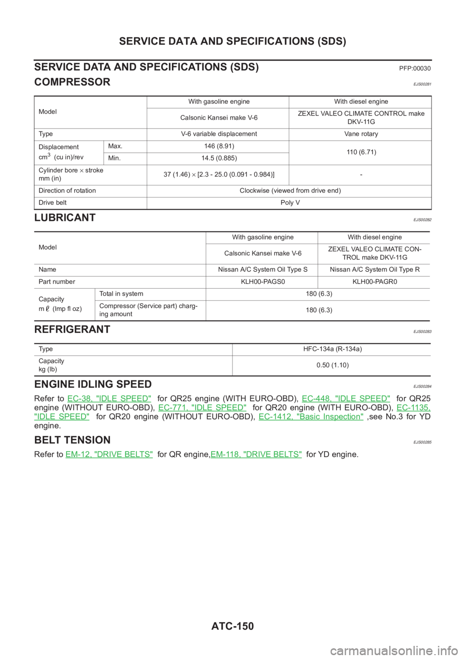
SERVICE DATA AND SPECIFICATIONS (SDS)
PFP:00030
COMPRESSOREJS00281
LUBRICANTEJS00282
REFRIGERANTEJS00283
ENGINE IDLING SPEEDEJS00284
Refer to EC-38, "IDLE SPEED" for QR25 engine (WITH EURO-OBD), EC-448, "IDLE SPEED" for QR25
engine (WITHOUT EURO-OBD), EC-771, "
IDLE SPEED" for QR20 engine (WITH EURO-OBD), EC-1135,
"IDLE SPEED" for QR20 engine (WITHOUT EURO-OBD), EC-1412, "Basic Inspection" ,see No.3 for YD
engine.
BELT TENSIONEJS00285
Refer to EM-12, "DRIVE BELTS" for QR engine,EM-118, "DRIVE BELTS" for YD engine.
ModelWith gasoline engine With diesel engine
Calsonic Kansei make V-6ZEXEL VALEO CLIMATE CONTROL make
DKV-11G
Type V-6 variable displacement Vane rotary
Displacement
cm
3 (cu in)/revMax. 146 (8.91)
110 (6.71)
Min. 14.5 (0.885)
Cylinder bore × stroke
mm (in)37 (1.46) × [2.3 - 25.0 (0.091 - 0.984)] -
Direction of rotation Clockwise (viewed from drive end)
Drive beltPoly V
ModelWith gasoline engine With diesel engine
Calsonic Kansei make V-6ZEXEL VALEO CLIMATE CON-
TROL make DKV-11G
Name Nissan A/C System Oil Type S Nissan A/C System Oil Type R
Part number KLH00-PAGS0 KLH00-PAGR0
Capacity
m (lmp fl oz)Total in system 180 (6.3)
Compressor (Service part) charg-
ing amount180 (6.3)
Ty p eHFC-134a (R-134a)
Capacity
kg (lb)0.50 (1.10)
Page 3493 of 3833
 “AIR BAG” and “SEAT
BELT PRE-TENSIONER”
EKS0079M
The Supplemental Restrain")
PRECAUTION
LT-3
C
D
E
F
G
H
I
J
L
MA
B
LT
PRECAUTION PFP:00011
Precautions for Supplemental Restraint System (SRS) “AIR BAG” and “SEAT
BELT PRE-TENSIONER”
EKS0079M
The Supplemental Restraint System such as “AIR BAG” and “SEAT BELT PRE-TENSIONER”, used along
with a front seat belt, helps to reduce the risk or severity of injury to the driver and front passenger for certain
types of collision. Information necessary to service the system safely is included in the SRS and SB section of
this Service Manual.
WARNING:
●To avoid rendering the SRS inoperative, which could increase the risk of personal injury or death
in the event of a collision which would result in air bag inflation, all maintenance must be per-
formed by an authorized NISSAN/INFINITI dealer.
●Improper maintenance, including incorrect removal and installation of the SRS, can lead to per-
sonal injury caused by unintentional activation of the system. For removal of Spiral Cable and Air
Bag Module, see the SRS section.
●Do not use electrical test equipment on any circuit related to the SRS unless instructed to in this
Service Manual. SRS wiring harnesses can be identified by yellow and/or orange harness connec-
tors.
Precaution EKS003KS
●Do not touch the glass of bulb directly by hand. Keep grease and other oily matters away from it. Do not
touch bulb by hand while it is lit or right after being turned off. Burning may result.
●Do not leave bulb out of headlamp reflector for a long time because dust, moisture smoke, etc. may affect
the performance of the headlamp. When replacing the bulb, be sure to replace it with a new one.
●Adjust aiming by tightening aiming screw. (To adjust it toward loosening side, first loosen adjusting screw,
and then make adjustment by tightening.)
●To remove soil or sealant of bulbs, do not use organic solvent (thinner, gasoline, etc.)
●When replacing bulb, be sure to hold bulb socket and pull it out straight. If wiring harness of the bulb is
pulled at an angle, the bulb may be caught in the lamp, making it difficult to take out.
Wiring Diagrams and Trouble Diagnosis EKS003KT
When you read wiring diagrams, refer to the followings:
●Refer to GI-13, "How to Read Wiring Diagrams" in GI section
●Refer to PG-2, "POWER SUPPLY ROUTING" for power distribution circuit in PG section
When you perform trouble diagnosis, refer to the followings:
●Refer to GI-10, "HOW TO FOLLOW TEST GROUPS IN TROUBLE DIAGNOSES" in GI section
●Refer toGI-23, "How to Perform Efficient Diagnosis for an Electrical Incident" in GI section
Page 3781 of 3833

MA-1
MAINTENANCE
L MAINTENANCE
CONTENTS
C
D
E
F
G
H
I
J
K
M
SECTION
A
B
MA
MAINTENANCE
PREPARATION ........................................................... 3
Special Service Tools ............................................... 3
Commercial Service Tools ........................................ 3
DESCRIPTION ............................................................ 4
Pre-delivery Inspection Items ................................... 4
GENERAL MAINTENANCE ....................................... 6
General Maintenance ............................................... 6
PERIODIC MAINTENANCE ....................................... 7
Periodic Maintenance ............................................... 7
ENGINE AND EMISSION CONTROL MAINTE-
NANCE (QR20DE AND QR25DE PETROL
ENGINE) ............................................................... 7
CHASSIS AND BODY MAINTENANCE
(QR20DE AND QR25DE PETROL ENGINE) ....... 7
ENGINE AND EMISSION CONTROL MAINTE-
NANCE (YD22DDTI DIESEL ENGINE) ................ 8
CHASSIS AND BODY MAINTENANCE
(YD22DDTI DIESEL ENGINE) .............................. 9
MAINTENANCE UNDER SEVERE DRIVING
CONDITIONS ...................................................... 10
ENGINE AND EMISSION CONTROL MAINTE-
NANCE (QR20DE AND QR25DE PETROL
ENGINE) .............................................................. 11
CHASSIS AND BODY MAINTENANCE
(QR20DE AND QR25DE PETROL ENGINE) ..... 12
ENGINE AND EMISSION CONTROL MAINTE-
NANCE (YD22DDTI DIESEL ENGINE) .............. 13
CHASSIS AND BODY MAINTENANCE
(YD22DDTI DIESEL ENGINE) ............................ 14
MAINTENANCE UNDER SEVERE DRIVING
CONDITIONS ...................................................... 14
RECOMMENDED FLUIDS AND LUBRICANTS ...... 16
Fluids and Lubricants ............................................. 16
SAE Viscosity Number ........................................... 17
GASOLINE ENGINE ........................................... 17
DIESEL ENGINE ................................................. 17
Engine Coolant Mixture Ratio ................................ 18
ENGINE MAINTENANCE (QR20DE·QR25DE) ........ 19
Checking Drive Belts .............................................. 19
Tension Adjustment ................................................ 19Changing Engine Coolant ....................................... 19
DRAINING ENGINE COOLANT .......................... 19
REFILLING ENGINE COOLANT ......................... 20
FLUSHING COOLING SYSTEM ......................... 21
Checking Cooling System ...................................... 21
CHECKING COOLING SYSTEM HOSES ........... 21
CHECKING RADIATOR ...................................... 21
CHECKING RADIATOR CAP .............................. 21
CHECKING RADIATOR SYSTEM FOR LEAKS ... 22
Checking Fuel Lines ............................................ ... 22
Changing Air Cleaner Filter .................................... 22
VISCOUS PAPER TYPE ..................................... 22
DRY PAPER TYPE .............................................. 22
Changing Engine Oil ............................................ ... 23
Changing Oil Filter .................................................. 23
Checking and Changing Spark Plugs ..................... 24
REMOVAL ........................................................... 24
INSPECTION AFTER REMOVAL ....................... 24
INSTALLATION ................................................... 25
Checking EVAP Vapor Lines .................................. 25
ENGINE MAINTENANCE (YD22DDTI) .................... 26
Checking Drive Belts .............................................. 26
Tension Adjustment ............................................. ... 26
AIR CONDITIONER COMPRESSOR BELT ........ 27
ALTERNATOR AND WATER PUMP BELT .......... 27
Changing Engine Coolant ....................................... 27
DRAINING ENGINE COOLANT .......................... 27
REFILLING ENGINE COOLANT ......................... 28
FLUSHING COOLING SYSTEM ......................... 29
Checking Cooling System ...................................... 29
CHECKING COOLING SYSTEM HOSES ........... 29
CHECKING RADIATOR ...................................... 29
CHECKING RADIATOR CAP .............................. 30
CHECKING RADIATOR SYSTEM FOR LEAKS ... 30
Checking Fuel Lines ............................................ ... 30
Changing Fuel Filter ............................................... 31
REMOVAL ........................................................... 31
INSTALLATION ................................................... 31
Changing Air Cleaner Filter .................................... 32
VISCOUS PAPER TYPE ..................................... 32