2001 NISSAN X-TRAIL App sensor
[x] Cancel search: App sensorPage 233 of 3833
![NISSAN X-TRAIL 2001 Service Repair Manual CYLINDER HEAD
EM-183
[YD22DDTi]
C
D
E
F
G
H
I
J
K
L
MA
EM
a. Turn the ignition switch to “OFF”.
b. Disconnect battery negative terminal.
c. Install glow plug and install all the parts removed in NISSAN X-TRAIL 2001 Service Repair Manual CYLINDER HEAD
EM-183
[YD22DDTi]
C
D
E
F
G
H
I
J
K
L
MA
EM
a. Turn the ignition switch to “OFF”.
b. Disconnect battery negative terminal.
c. Install glow plug and install all the parts removed in](/manual-img/5/57405/w960_57405-232.png)
CYLINDER HEAD
EM-183
[YD22DDTi]
C
D
E
F
G
H
I
J
K
L
MA
EM
a. Turn the ignition switch to “OFF”.
b. Disconnect battery negative terminal.
c. Install glow plug and install all the parts removed in step 4.
d. Install fuel supply pump fuse [ENG CONT (20A)].
e. Connect battery negative terminal.
f. Using CONSULT-II make sure no error code is indicated for items of self-diagnosis.
Removal and InstallationEBS00LRW
CAUTION:
Apply new engine oil to parts marked in illustration before installation.
REMOVAL
1. Drain engine coolant. Refer to CO-29, "Changing Engine Coolant" .
2. Remove the following parts:
●Charge air cooler (Refer to EM-122, "Removal and Installation" .)
●Rocker cover (Refer to EM-156, "Removal and Installation" .)
●Air cleaner and air duct (Refer to EM-120, "Removal and Installation" .)
●Vacuum pump (Refer to EM-139, "Removal and Installation" .)
●Injection tube, spill tube and fuel injector (Refer to EM-144, "Removal and Installation" .)
●Intake manifold (Refer to EM-123, "Removal and Installation" .)
●Exhaust manifold and Turbocharger (Refer to EM-127, "Removal and Installation" .)
●Secondary timing chain (Refer to EM-167, "Removal and Installation" .)
●Camshaft (Refer to EM-158, "Removal and Installation" .)
SBIA0193E
1. Glow plug 2. Cylinder head assembly 3. Cylinder head bolt
4. Thermal transmitter 5. Engine coolant temperature sensor 6. Gasket
7. Water outlet 8. Glow plate
Page 236 of 3833
![NISSAN X-TRAIL 2001 Service Repair Manual EM-186
[YD22DDTi]
CYLINDER HEAD
*: Measured with head bolts tightened
2. Apply a continuous bead of Genuine Liquid Gasket or equivalent
on the surface shown in the figure.
A: Apply bead so that it doe NISSAN X-TRAIL 2001 Service Repair Manual EM-186
[YD22DDTi]
CYLINDER HEAD
*: Measured with head bolts tightened
2. Apply a continuous bead of Genuine Liquid Gasket or equivalent
on the surface shown in the figure.
A: Apply bead so that it doe](/manual-img/5/57405/w960_57405-235.png)
EM-186
[YD22DDTi]
CYLINDER HEAD
*: Measured with head bolts tightened
2. Apply a continuous bead of Genuine Liquid Gasket or equivalent
on the surface shown in the figure.
A: Apply bead so that it does not protrude into oil passage. Refer
to E M - 111 , "
Precautions For Liquid Gasket" .
B: Minimize the overlapping area of the bead, with start and end
areas of bead as shown in the figure.
Apply so that the portion marked * comes at an external loca-
tion but cannot be viewed externally after engine is assembled.
3. Install cylinder head assembly.
●Tighten bolts in numerical order as shown in the figure
according to the following procedure:
a. Apply engine oil to bolt threads and seat surfaces.
b. Tighten bolts to 29 to 38 N·m (2.9 to 3.9 kg-m, 21 to 28 ft-lb).
c. Tighten 180° to 185° [target: 180°] (angular tightening).
d. Loosen completely to 0 N·m (0 kg-m, 0 in-lb) in the reverse order
of that shown in the figure.
e. Tighten bolts to 35 to 44 N·m (3.5 to 4.5 kg-m, 26 to 32 ft-lb).
f. Tighten 90° to 95° [target: 90°] (angular tightening)
g. Tighten another 90° to 95° [target: 90°] (angular tightening).
●When an angle wrench is not used, paint an alignment
mark on the head of cylinder head bolt and cylinder head
surface before tightening. Check the angle with a protrac-
tor.
4. Install glow plug.
●To avoid damage, glow plugs should be removed only
when required.
●Handle with care to avoid applying shock. When dropped
from approx. 100 mm (3.94 in) or higher, always replace
with a new one.
●Before installing, remove carbon depositing on mounting hole of glow plug with a reamer.
5. Install engine coolant temperature sensor and thermal transmitter.
PBIC1256E
JEM149G
JEM166G
Page 327 of 3833
![NISSAN X-TRAIL 2001 Service Repair Manual THERMOSTAT AND WATER CONTROL VALVE
CO-21
[QR]
C
D
E
F
G
H
I
J
K
L
MA
CO
INSPECTION AFTER REMOVAL
●Place a string so that it is caught in the valves of the thermostat
and water control valve. Imm NISSAN X-TRAIL 2001 Service Repair Manual THERMOSTAT AND WATER CONTROL VALVE
CO-21
[QR]
C
D
E
F
G
H
I
J
K
L
MA
CO
INSPECTION AFTER REMOVAL
●Place a string so that it is caught in the valves of the thermostat
and water control valve. Imm](/manual-img/5/57405/w960_57405-326.png)
THERMOSTAT AND WATER CONTROL VALVE
CO-21
[QR]
C
D
E
F
G
H
I
J
K
L
MA
CO
INSPECTION AFTER REMOVAL
●Place a string so that it is caught in the valves of the thermostat
and water control valve. Immerse fully in a container filled with
water. Heat while stirring. (The example in the figure shows the
thermostat.)
●The valve opening temperature is the temperature at which the
valve opens and the falls from the thread.
●Continue heating. Check the full-open lift amount.
NOTE:
The full-open lift amount standard temperature for the water
control valve is the reference value.
● After checking the full-open lift amount, lower the water temper-
ature and check the valve closing temperature.
Standard values
INSTALLATION
Install in the reverse order of removal paying attention to the following.
●Install the engine coolant temperature sensor.
Use Genuine Liquid Gasket or equivalent.
Installation of Thermostat and Water Control Valve
●Install the thermostat and water control valve with the whole cir-
cumference of each flange part fit securely inside the rubber
ring. (The example in the figure shows the thermostat.)
●Install the thermostat with the jiggle valve facing upwards. (The
position deviation may be within the range of ±10°)
●Install the water control valve with the up-mark facing up and the
frame center part facing upwards. (The position deviation may
be within the range of ±10°)
Heater Pipe Installation
First apply a neutral detergent to the O-ring, then quickly insert the insertion parts of the heater pipe into the
installation holes.
SLC252B
Thermostat Water control valve
Valve opening temperature 80.5 - 83.5°C (177 - 182° F) 93.5 - 96.5°C (200 - 206°F)
Full-open lift amountMore than 8 mm/ 95°C
(0.315 in/ 203 °F)More than 8 mm/ 108°C
(0.315 in/ 226 ° F)
Valve closing temperature 77°C (171°F) 90°C (194° F)
PBIC0157E
PBIC0158E
Page 328 of 3833
![NISSAN X-TRAIL 2001 Service Repair Manual CO-22
[QR]
SERVICE DATA AND SPECIFICATIONS (SDS)
SERVICE DATA AND SPECIFICATIONS (SDS)
PFP:00030
Standard and LimitEBS00KOP
CAPACITY
Unit: (lmp qt)
THERMOSTAT
WATER CONTROL VALVE
RADIATOR
Unit: kPa NISSAN X-TRAIL 2001 Service Repair Manual CO-22
[QR]
SERVICE DATA AND SPECIFICATIONS (SDS)
SERVICE DATA AND SPECIFICATIONS (SDS)
PFP:00030
Standard and LimitEBS00KOP
CAPACITY
Unit: (lmp qt)
THERMOSTAT
WATER CONTROL VALVE
RADIATOR
Unit: kPa](/manual-img/5/57405/w960_57405-327.png)
CO-22
[QR]
SERVICE DATA AND SPECIFICATIONS (SDS)
SERVICE DATA AND SPECIFICATIONS (SDS)
PFP:00030
Standard and LimitEBS00KOP
CAPACITY
Unit: (lmp qt)
THERMOSTAT
WATER CONTROL VALVE
RADIATOR
Unit: kPa (bar, kg/cm2 , psi)
Tightening TorqueEBS00KOQ
Unit: N·m (kg-m, ft-lb)
Unit: N·m (kg-m, in-lb)*
Engine coolant capacity [With reservoir tank (MAX level)] Approximately 7.1 (6-1/4)
Reservoir tank0.6 (1/2)
Valve opening temperature 80.5 - 83.5°C (177 - 182°F)
Valve liftMore than 8 mm/ 95°C (0.315 in/203°F)
Valve closing temperature 77°C (171°F)
Valve opening temperature 93.5 - 96.5°C (200 - 206°F)
Valve liftMore than 8 mm/108°C (0.315 in/226°F)
Valve closing temperature 90°C (194° F)
Cap relief pressureStandard 78 - 98 (0.78 - 0.98, 0.8 - 1.0, 11- 14)
Limit 59 (0.59, 0.6, 9)
Leakage test pressure 157 (1.57, 1.6, 23)
Cylinder block drain plug 7.8 - 11.8 (0.8 - 1.2, 69 - 104)*
Radiator mounting bracket 3.8 - 4.5 (0.39 - 0.46, 34 - 39)*
Radiator fan assembly 3.8 - 4.5 (0.39 - 0.46, 34 - 39)*
Radiator fan2.9 - 3.9 (0.30 - 0.40, 26 - 34)*
Radiator fan motor 3.9 - 4.9 (0.40 - 0.50, 35 - 43)*
Water pump20.8 - 28.2 (2.1 - 2.9, 16 - 20)
Water pump housing 20.8 - 28.2 (2.1 - 2.9, 16 - 20)
Water inlet20.8 - 28.2 (2.1 - 2.9, 16 - 20)
Water outlet20.8 - 28.2 (2.1 - 2.9, 16 - 20)
Water pipe20.8 - 28.2 (2.1 - 2.9, 16 - 20)
Hater pipe20.8 - 28.2 (2.1 - 2.9, 16 - 20)
Engine coolant temperature sensor 19.6 - 29.4 (2.0 - 3.0, 15 - 21)
Page 355 of 3833

EC-5
C
D
E
F
G
H
I
J
K
L
M
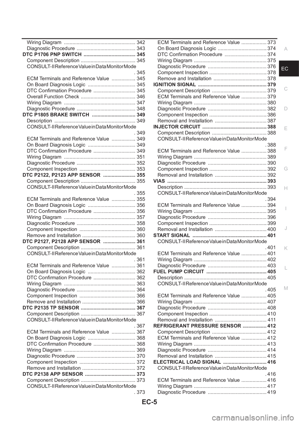
ECA Wiring Diagram .................................................... 342
Diagnostic Procedure ........................................... 343
DTC P1706 PNP SWITCH ...................................... 345
Component Description ........................................ 345
CONSULT-II Reference Value in Data Monitor Mode
. 345
ECM Terminals and Reference Value .................. 345
On Board Diagnosis Logic ................................... 345
DTC Confirmation Procedure ............................... 345
Overall Function Check ........................................ 346
Wiring Diagram .................................................... 347
Diagnostic Procedure ........................................... 348
DTC P1805 BRAKE SWITCH ................................ 349
Description ........................................................... 349
CONSULT-II Reference Value in Data Monitor Mode
. 349
ECM Terminals and Reference Value .................. 349
On Board Diagnosis Logic ................................... 349
DTC Confirmation Procedure ............................... 349
Wiring Diagram .................................................... 351
Diagnostic Procedure ........................................... 352
Component Inspection ......................................... 353
DTC P2122, P2123 APP SENSOR ........................ 355
Component Description ........................................ 355
CONSULT-II Reference Value in Data Monitor Mode
. 355
ECM Terminals and Reference Value .................. 355
On Board Diagnosis Logic ................................... 356
DTC Confirmation Procedure ............................... 356
Wiring Diagram .................................................... 357
Diagnostic Procedure ........................................... 358
Component Inspection ......................................... 360
Remove and Installation ....................................... 360
DTC P2127, P2128 APP SENSOR ........................ 361
Component Description ........................................ 361
CONSULT-II Reference Value in Data Monitor Mode
. 361
ECM Terminals and Reference Value .................. 361
On Board Diagnosis Logic ................................... 362
DTC Confirmation Procedure ............................... 362
Wiring Diagram .................................................... 363
Diagnostic Procedure ........................................... 364
Component Inspection ......................................... 366
Remove and Installation ....................................... 366
DTC P2135 TP SENSOR ........................................ 367
Component Description ........................................ 367
CONSULT-II Reference Value in Data Monitor Mode
. 367
ECM Terminals and Reference Value .................. 367
On Board Diagnosis Logic ................................... 368
DTC Confirmation Procedure ............................... 368
Wiring Diagram ................................................
.... 369
Diagnostic Procedure ........................................... 370
Component Inspection ......................................... 372
Remove and Installation ....................................... 372
DTC P2138 APP SENSOR ..................................... 373
Component Description ........................................ 373
CONSULT-II Reference Value in Data Monitor Mode
. 373ECM Terminals and Reference Value ...................373
On Board Diagnosis Logic ....................................374
DTC Confirmation Procedure ...............................374
Wiring Diagram .....................................................375
Diagnostic Procedure ...........................................376
Component Inspection ..........................................378
Remove and Installation .......................................378
IGNITION SIGNAL ..................................................379
Component Description ........................................379
ECM Terminals and Reference Value ...................379
Wiring Diagram .....................................................380
Diagnostic Procedure ...........................................382
Component Inspection ..........................................386
Removal and Installation ......................................387
INJECTOR CIRCUIT ...............................................388
Component Description ........................................388
CONSULT-II Reference Value in Data Monitor Mode
.388
ECM Terminals and Reference Value ...................388
Wiring Diagram .....................................................389
Diagnostic Procedure ...........................................390
Component Inspection ..........................................392
Removal and Installation ......................................392
VIAS ........................................................................393
Description ............................................................393
CONSULT-II Reference Value in Data Monitor Mode
.394
ECM Terminals and Reference Value ...................394
Wiring Diagram .....................................................395
Diagnostic Procedure ...........................................396
Component Inspection ..........................................399
Removal and Installation ......................................400
START SIGNAL ......................................................401
CONSULT-II Reference Value in Data Monitor Mode
.401
ECM Terminals and Reference Value ...................401
Wiring Diagram .....................................................402
Diagnostic Procedure ...........................................403
FUEL PUMP CIRCUIT ............................................405
Description ............................................................405
CONSULT-II Reference Value in Data Monitor Mode
.405
ECM Terminals and Reference Value ..................
.405
Wiring Diagram .....................................................407
Diagnostic Procedure ...........................................408
Component Inspection ..........................................410
Removal and Installation ......................................411
REFRIGERANT PRESSURE SENSOR ..................412
Component Description ........................................412
ECM Terminals and Reference Value ...................412
Wiring Diagram .....................................................413
Diagnostic Procedure ...........................................414
Removal and Installation ......................................415
ELECTRICAL LOAD SIGNAL ................................416
CONSULT-II Reference Value in Data Monitor Mode
.416
ECM Terminals and Reference Value ...................416
Wiring Diagram .....................................................417
Diagnostic Procedure ...........................................419
Page 358 of 3833

EC-8
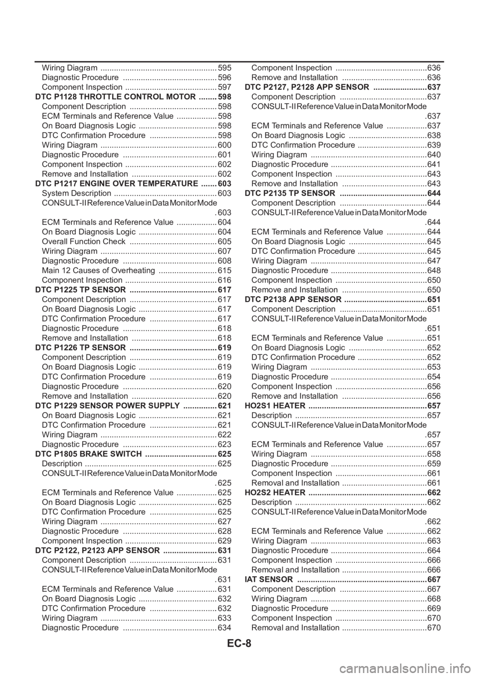
Wiring Diagram .....................................................595
Diagnostic Procedure ...........................................596
Component Inspection ..........................................597
DTC P1128 THROTTLE CONTROL MOTOR .........598
Component Description ........................................598
ECM Terminals and Reference Value ...................598
On Board Diagnosis Logic ....................................598
DTC Confirmation Procedure ...............................598
Wiring Diagram .....................................................600
Diagnostic Procedure ...........................................601
Component Inspection ..........................................602
Remove and Installation .......................................602
DTC P1217 ENGINE OVER TEMPERATURE ........603
System Description ...............................................603
CONSULT-II Reference Value in Data Monitor Mode
.603
ECM Terminals and Reference Value ...................604
On Board Diagnosis Logic ....................................604
Overall Function Check ........................................605
Wiring Diagram .....................................................607
Diagnostic Procedure ...........................................608
Main 12 Causes of Overheating ...........................615
Component Inspection ..........................................616
DTC P1225 TP SENSOR ........................................617
Component Description ........................................617
On Board Diagnosis Logic ....................................617
DTC Confirmation Procedure ...............................617
Diagnostic Procedure ...........................................618
Remove and Installation .......................................618
DTC P1226 TP SENSOR ........................................619
Component Description ........................................619
On Board Diagnosis Logic ....................................619
DTC Confirmation Procedure ...............................619
Diagnostic Procedure ...........................................620
Remove and Installation .......................................620
DTC P1229 SENSOR POWER SUPPLY ................621
On Board Diagnosis Logic ....................................621
DTC Confirmation Procedure ...............................621
Wiring Diagram .....................................................622
Diagnostic Procedure ...........................................623
DTC P1805 BRAKE SWITCH .................................625
Description ............................................................625
CONSULT-II Reference Value in Data Monitor Mode
.625
ECM Terminals and Reference Value ...................625
On Board Diagnosis Logic ....................................625
DTC Confirmation Procedure ...............................625
Wiring Diagram .....................................................627
Diagnostic Procedure ...........................................628
Component Inspection ..........................................629
DTC P2122, P2123 APP SENSOR .........................631
Component Description ........................................631
CONSULT-II Reference Value in Data Monitor Mode
.631
ECM Terminals and Reference Value ...................631
On Board Diagnosis Logic ....................................632
DTC Confirmation Procedure ...............................632
Wiring Diagram .....................................................633
Diagnostic Procedure ...........................................634Component Inspection ..........................................636
Remove and Installation .......................................636
DTC P2127, P2128 APP SENSOR .........................637
Component Description ........................................637
CONSULT-II Reference Value in Data Monitor Mode
.637
ECM Terminals and Reference Value ...................637
On Board Diagnosis Logic ....................................638
DTC Confirmation Procedure ................................639
Wiring Diagram .....................................................640
Diagnostic Procedure ............................................641
Component Inspection ..........................................643
Remove and Installation .......................................643
DTC P2135 TP SENSOR ........................................644
Component Description ........................................644
CONSULT-II Reference Value in Data Monitor Mode
.644
ECM Terminals and Reference Value ...................644
On Board Diagnosis Logic ....................................645
DTC Confirmation Procedure ................................645
Wiring Diagram .....................................................647
Diagnostic Procedure ............................................648
Component Inspection ..........................................650
Remove and Installation .......................................650
DTC P2138 APP SENSOR ......................................651
Component Description ........................................651
CONSULT-II Reference Value in Data Monitor Mode
.651
ECM Terminals and Reference Value ...................651
On Board Diagnosis Logic ....................................652
DTC Confirmation Procedure ................................652
Wiring Diagram .....................................................653
Diagnostic Procedure ............................................654
Component Inspection ..........................................656
Remove and Installation .......................................656
HO2S1 HEATER ......................................................657
Description ............................................................657
CONSULT-II Reference Value in Data Monitor Mode
.657
ECM Terminals and Reference Value ...................657
Wiring Diagram ....................................................
.658
Diagnostic Procedure ............................................659
Component Inspection ..........................................661
Removal and Installation .......................................661
HO2S2 HEATER ......................................................662
Description ............................................................662
CONSULT-II Reference Value in Data Monitor Mode
.662
ECM Terminals and Reference Value ...................662
Wiring Diagram .....................................................663
Diagnostic Procedure ............................................664
Component Inspection ..........................................666
Removal and Installation .......................................666
IAT SENSOR ...........................................................667
Component Description ........................................667
Wiring Diagram .....................................................668
Diagnostic Procedure ............................................669
Component Inspection ..........................................670
Removal and Installation .......................................670
Page 361 of 3833

EC-11
C
D
E
F
G
H
I
J
K
L
M
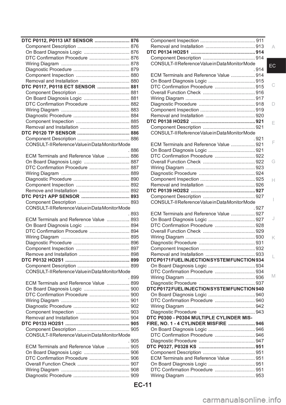
ECA DTC P0112, P0113 IAT SENSOR ........................... 876
Component Description ........................................ 876
On Board Diagnosis Logic ................................... 876
DTC Confirmation Procedure ............................... 876
Wiring Diagram .................................................... 878
Diagnostic Procedure ........................................... 879
Component Inspection ......................................... 880
Removal and Installation ...................................... 880
DTC P0117, P0118 ECT SENSOR ......................... 881
Component Description ........................................ 881
On Board Diagnosis Logic ................................... 881
DTC Confirmation Procedure ............................... 882
Wiring Diagram .................................................... 883
Diagnostic Procedure ........................................... 884
Component Inspection ......................................... 885
Removal and Installation ...................................... 885
DTC P0120 TP SENSOR ........................................ 886
Component Description ........................................ 886
CONSULT-II Reference Value in Data Monitor Mode
. 886
ECM Terminals and Reference Value .................. 886
On Board Diagnosis Logic ................................... 887
DTC Confirmation Procedure ............................... 887
Wiring Diagram .................................................... 889
Diagnostic Procedure ........................................... 890
Component Inspection ......................................... 892
Remove and Installation ....................................... 892
DTC P0121 APP SENSOR ..................................... 893
Component Description ........................................ 893
CONSULT-II Reference Value in Data Monitor Mode
. 893
ECM Terminals and Reference Value .................. 893
On Board Diagnosis Logic ................................... 894
DTC Confirmation Procedure ............................... 894
Wiring Diagram .................................................... 895
Diagnostic Procedure ........................................... 896
Component Inspection ......................................... 897
Remove and Installation ....................................... 898
DTC P0132 HO2S1 ................................................. 899
Component Description ........................................ 899
CONSULT-II Reference Value in Data Monitor Mode
. 899
ECM Terminals and Reference Value .................. 899
On Board Diagnosis Logic ................................... 900
DTC Confirmation Procedure ............................... 900
Wiring Diagram .................................................... 901
Diagnostic Procedure ........................................... 902
Component Inspection ......................................... 903
Removal and Installation ...................................... 904
DTC P0133 HO2S1 ...............................................
.. 905
Component Description ........................................ 905
CONSULT-II Reference Value in Data Monitor Mode
. 905
ECM Terminals and Reference Value .................. 905
On Board Diagnosis Logic ................................... 906
DTC Confirmation Procedure ............................... 906
Overall Function Check ........................................ 907
Wiring Diagram .................................................... 908
Diagnostic Procedure ........................................... 909Component Inspection ..........................................911
Removal and Installation ......................................913
DTC P0134 HO2S1 ................................................ .914
Component Description ........................................914
CONSULT-II Reference Value in Data Monitor Mode
.914
ECM Terminals and Reference Value ...................914
On Board Diagnosis Logic ....................................915
DTC Confirmation Procedure ...............................915
Overall Function Check ........................................916
Wiring Diagram .....................................................917
Diagnostic Procedure ...........................................918
Component Inspection ..........................................919
Removal and Installation ......................................920
DTC P0138 HO2S2 ................................................ .921
Component Description ........................................921
CONSULT-II Reference Value in Data Monitor Mode
.921
ECM Terminals and Reference Value ...................921
On Board Diagnosis Logic ....................................921
DTC Confirmation Procedure ...............................922
Overall Function Check ........................................922
Wiring Diagram .....................................................923
Diagnostic Procedure ...........................................924
Component Inspection ..........................................925
Removal and Installation ......................................926
DTC P0139 HO2S2 ................................................ .927
Component Description ........................................927
CONSULT-II Reference Value in Data Monitor Mode
.927
ECM Terminals and Reference Value ...................927
On Board Diagnosis Logic ....................................927
DTC Confirmation Procedure ...............................928
Overall Function Check ........................................929
Wiring Diagram .....................................................930
Diagnostic Procedure ...........................................931
Component Inspection ..........................................932
Removal and Installation ......................................933
DTC P0171 FUEL INJECTION SYSTEM FUNCTION .934
On Board Diagnosis Logic ....................................934
DTC Confirmation Procedure ...............................934
Wiring Diagram .....................................................936
Diagnostic Procedure ...........................................937
DTC P0172 FUEL INJECTION SYSTEM FUNCTION .940
On Board Diagnosis Logic ....................................940
DTC Confirmation Procedure ...............................940
Wiring Diagram .....................................................942
Diagnostic Procedure ...........................................943
DTC P0300 - P0304 MULTIPLE CYLINDER MIS-
FIRE, NO. 1 - 4 CYLINDER MISFIRE .....................946
On Board Diagnosis Logic ....................................946
DTC Confirmation Procedure ...............................946
Diagnostic Procedure ...........................................947
DTC P0327, P0328 KS ...........................................951
Component Description ........................................951
ECM Terminals and Reference Value ...................951
On Board Diagnosis Logic ....................................951
DTC Confirmation Procedure ...............................951
Wiring Diagram .....................................................953
Page 365 of 3833

EC-15
C
D
E
F
G
H
I
J
K
L
M
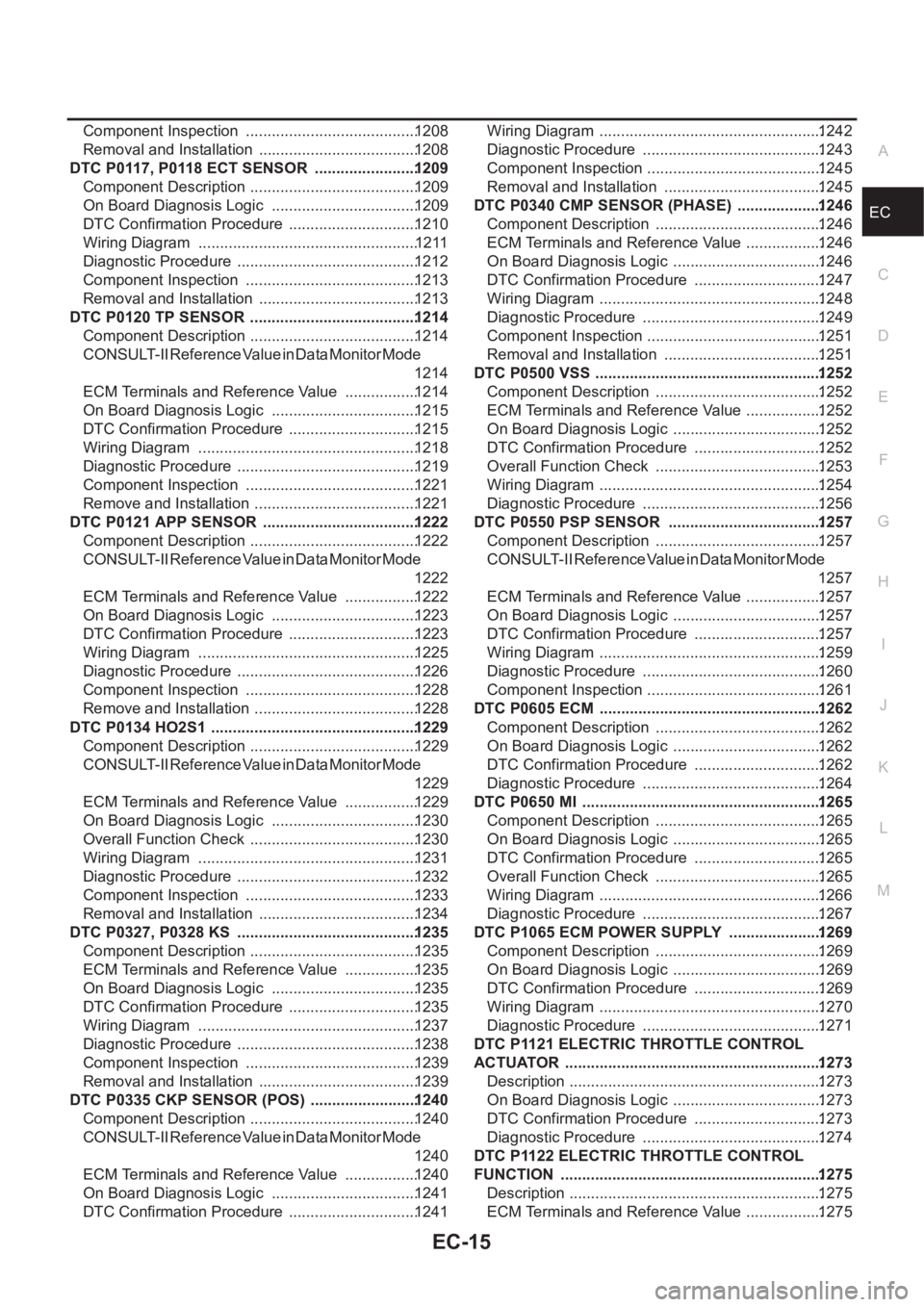
ECA Component Inspection ........................................1208
Removal and Installation .....................................1208
DTC P0117, P0118 ECT SENSOR ........................1209
Component Description .......................................1209
On Board Diagnosis Logic ..................................1209
DTC Confirmation Procedure ..............................1210
Wiring Diagram ...................................................1211
Diagnostic Procedure ..........................................1212
Component Inspection ........................................1213
Removal and Installation .....................................1213
DTC P0120 TP SENSOR .......................................1214
Component Description .......................................1214
CONSULT-II Reference Value in Data Monitor Mode
1214
ECM Terminals and Reference Value .................1214
On Board Diagnosis Logic ..................................1215
DTC Confirmation Procedure ..............................1215
Wiring Diagram ...................................................1218
Diagnostic Procedure ..........................................1219
Component Inspection ........................................1221
Remove and Installation ......................................1221
DTC P0121 APP SENSOR ....................................1222
Component Description .......................................1222
CONSULT-II Reference Value in Data Monitor Mode
1222
ECM Terminals and Reference Value .................1222
On Board Diagnosis Logic ..................................1223
DTC Confirmation Procedure ..............................1223
Wiring Diagram ...................................................1225
Diagnostic Procedure ..........................................1226
Component Inspection ........................................1228
Remove and Installation ......................................1228
DTC P0134 HO2S1 ................................................1229
Component Description .......................................1229
CONSULT-II Reference Value in Data Monitor Mode
1229
ECM Terminals and Reference Value .................1229
On Board Diagnosis Logic ..................................1230
Overall Function Check .......................................1230
Wiring Diagram ...................................................1231
Diagnostic Procedure ..........................................1232
Component Inspection ........................................1233
Removal and Installation .....................................1234
DTC P0327, P0328 KS ..........................................1235
Component Description .......................................1235
ECM Terminals and Reference Value .................1235
On Board Diagnosis Logic ..................................1235
DTC Confirmation Procedure ..............................1235
Wiring Diagram ...................................................1237
Diagnostic Procedure ..........................................1238
Component Inspection ........................................1239
Removal and Installation .....................................1239
DTC P0335 CKP SENSOR (POS) .........................1240
Component Description .......................................1240
CONSULT-II Reference Value in Data Monitor Mode
1240
ECM Terminals and Reference Value .................1240
On Board Diagnosis Logic ..................................1241
DTC Confirmation Procedure ..............................1241Wiring Diagram ....................................................1242
Diagnostic Procedure ..........................................1243
Component Inspection .........................................1245
Removal and Installation .....................................1245
DTC P0340 CMP SENSOR (PHASE) ....................1246
Component Description .......................................1246
ECM Terminals and Reference Value ..................1246
On Board Diagnosis Logic ...................................1246
DTC Confirmation Procedure ..............................1247
Wiring Diagram ....................................................1248
Diagnostic Procedure ..........................................1249
Component Inspection .........................................1251
Removal and Installation .....................................1251
DTC P0500 VSS .....................................................1252
Component Description .......................................1252
ECM Terminals and Reference Value ..................1252
On Board Diagnosis Logic ...................................1252
DTC Confirmation Procedure ..............................1252
Overall Function Check .......................................1253
Wiring Diagram ....................................................1254
Diagnostic Procedure ..........................................1256
DTC P0550 PSP SENSOR ....................................1257
Component Description .......................................1257
CONSULT-II Reference Value in Data Monitor Mode
1257
ECM Terminals and Reference Value ..................1257
On Board Diagnosis Logic ...................................1257
DTC Confirmation Procedure ..............................1257
Wiring Diagram ....................................................1259
Diagnostic Procedure ..........................................1260
Component Inspection .........................................1261
DTC P0605 ECM ....................................................1262
Component Description .......................................1262
On Board Diagnosis Logic ...................................1262
DTC Confirmation Procedure ..............................1262
Diagnostic Procedure ..........................................1264
DTC P0650 MI ........................................................1265
Component Description .......................................1265
On Board Diagnosis Logic ...................................1265
DTC Confirmation Procedure ..............................1265
Overall Function Check .......................................1265
Wiring Diagram ....................................................1266
Diagnostic Procedure ..........................................1267
DTC P1065 ECM POWER SUPPLY ......................1269
Component Description .......................................1269
On Board Diagnosis Logic ...................................1269
DTC Confirmation Procedure ..............................1269
Wiring Diagram ....................................................1270
Diagnostic Procedure ..........................................1271
DTC P1121 ELECTRIC THROTTLE CONTROL
ACTUATOR ............................................................1273
Description ...........................................................1273
On Board Diagnosis Logic ...................................1273
DTC Confirmation Procedure ..............................1273
Diagnostic Procedure ..........................................1274
DTC P1122 ELECTRIC THROTTLE CONTROL
FUNCTION .............................................................1275
Description ...........................................................1275
ECM Terminals and Reference Value ..................1275