Page 2940 of 3833
PS-30
POWER STEERING OIL PUMP
Disassembly and Assembly (YD22DDTi engine model)
EGS000AJ
INSPECTION BEFORE DISASSEMBLY
Disassemble power steering oil pump only when any of following
cases meets.
●If oil leak is found on oil pump.
●Oil pump pulley is deformed or damaged.
●Performance of oil pump is low.
1. Rear bracket 2. Rear body 3. Dowel pin
4. Side plate seal 5. Cam ring 6. Vane
7. Rotor 8. Side plate 9. O-ring (Outer)
10. O-ring (Inner) 11. Front body 12. Drive shaft rear oil sear
13. Drive shaft front oil seal 14. Drive shaft 15. Snap ring
16. O-ring 17. Outlet connector 18. Connector seal
19. Flow control valve 20. Flow control valve spring 21. Inlet connector
22. O-ring 23. Copper washer
SST882CA
SST883C
Page 2941 of 3833
POWER STEERING OIL PUMP
PS-31
C
D
E
F
H
I
J
K
L
MA
B
PS
DISASSEMBLY
CAUTION:
●Parts which can be disassembled are strictly limited. Never disassemble parts other than those
specified.
●Disassemble in as clean a place as possible.
●Clean your hands before disassembly.
●Do not use rags; use nylon cloths or paper towels.
●Follow the procedure and cautions in the Service Manual.
●When disassembling and reassembling, do not let foreign matter enter or contact the parts.
1. Remove rear bracket and rear body.
2. Remove side plate seal, cam ring, vane, rotor and side plate.
3. Remove out connector and then remove connector seal, flow
control valve and flow control valve spring.
CAUTION:
●Be careful not to drop the flow control valve.
●Do not disassemble the flow control valve.
4. Remove oil seal
5. Remove snap ring, then draw drive shaft.
CAUTION:
Be careful not to drop drive shaft.
6. Remove inlet connector.
SST887C
SST036A
SST888C
SST889C
Page 2942 of 3833
PS-32
POWER STEERING OIL PUMP
INSPECTION AFTER DISASSEMBLY
●If pulley is cracked or deformed, replace it.
●If an oil leak is found around pulley shaft oil seal, replace the seal.
●If serration on pulley or pulley shaft is deformed or worn, replace it.
ASSEMBLY
1. Assemble oil pump, noting the following instructions.
●Make sure O-rings and oil seal are properly installed.
●Always install new O-rings and oil seal.
●Be careful of oil seal direction.
●Cam ring, rotor and vanes must be replaced as a set if neces-
sary.
●Coat each part with DEXRONTM III or equivalent when
assembling.
2. Pay attention to the direction of rotor.
3. When assembling vanes to rotor, rounded surfaces of vanes
must face cam ring side.
SST036A
SST289A
SST843A
Page 2943 of 3833
POWER STEERING OIL PUMP
PS-33
C
D
E
F
H
I
J
K
L
MA
B
PS
4. Insert pin 2 into pin groove 1 of front housing and front side
plate. Then install cam ring 3 as shown at left.
Cam ring : D
1 is less than D2
SST472C
Page 2947 of 3833

SERVICE DATA AND SPECIFICATIONS (SDS)
PS-37
C
D
E
F
H
I
J
K
L
MA
B
PS
Steering GearEGS0004T
Oil PumpEGS0004U
Steering FluidEGS0004V
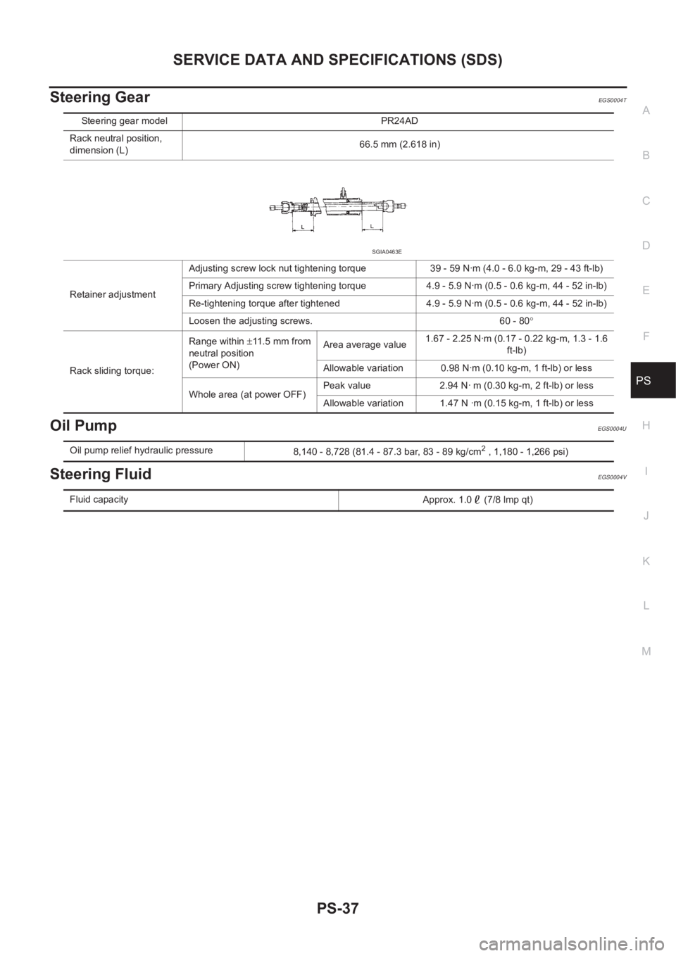
Steering gear model PR24AD
Rack neutral position,
dimension (L)66.5 mm (2.618 in)
Retainer adjustmentAdjusting screw lock nut tightening torque 39 - 59 N·m (4.0 - 6.0 kg-m, 29 - 43 ft-lb)
Primary Adjusting screw tightening torque 4.9 - 5.9 N·m (0.5 - 0.6 kg-m, 44 - 52 in-lb)
Re-tightening torque after tightened 4.9 - 5.9 N·m (0.5 - 0.6 kg-m, 44 - 52 in-lb)
Loosen the adjusting screws. 60 - 80°
Rack sliding torque:Range within ±11.5 mm from
neutral position
(Power ON)Area average value1.67 - 2.25 N·m (0.17 - 0.22 kg-m, 1.3 - 1.6
ft-lb)
Allowable variation 0.98 N·m (0.10 kg-m, 1 ft-lb) or less
Whole area (at power OFF)Peak value 2.94 N· m (0.30 kg-m, 2 ft-lb) or less
Allowable variation 1.47 N ·m (0.15 kg-m, 1 ft-lb) or less
SGIA0463E
Oil pump relief hydraulic pressure
8,140 - 8,728 (81.4 - 87.3 bar, 83 - 89 kg/cm2 , 1,180 - 1,266 psi)
Fluid capacity
Approx. 1.0 (7/8 lmp qt)
Page 3005 of 3833

PRECAUTIONS
SRS-3
C
D
E
F
G
I
J
K
L
MA
B
SRS
PRECAUTIONSPFP:00001
Precautions for Supplemental Restraint System (SRS) “AIR BAG” and “SEAT
BELT PRE-TENSIONER”
EHS000QI
The Supplemental Restraint System such as “AIR BAG” and “SEAT BELT PRE-TENSIONER”, used along
with a front seat belt, helps to reduce the risk or severity of injury to the driver and front passenger for certain
types of collision. Information necessary to service the system safely is included in the SRS and SB section of
this Service Manual.
WARNING:
●To avoid rendering the SRS inoperative, which could increase the risk of personal injury or death
in the event of a collision which would result in air bag inflation, all maintenance must be per-
formed by an authorized NISSAN/INFINITI dealer.
●Improper maintenance, including incorrect removal and installation of the SRS, can lead to per-
sonal injury caused by unintentional activation of the system. For removal of Spiral Cable and Air
Bag Module, see the SRS section.
●Do not use electrical test equipment on any circuit related to the SRS unless instructed to in this
Service Manual. SRS wiring harnesses can be identified by yellow and/or orange harness connec-
tors.
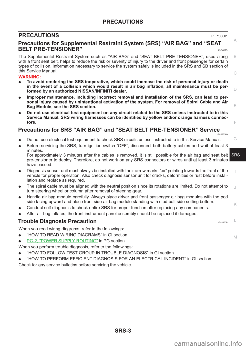
Precautions for SRS “AIR BAG” and “SEAT BELT PRE-TENSIONER” ServiceEHS000BH
●Do not use electrical test equipment to check SRS circuits unless instructed to in this Service Manual.
●Before servicing the SRS, turn ignition switch “OFF”, disconnect both battery cables and wait at least 3
minutes.
For approximately 3 minutes after the cables is removed, it is still possible for the air bag and seat belt
pre-tensioner to deploy. Therefore, do not work on any SRS connectors or wires until at least 3 minutes
have passed.
●Diagnosis sensor unit must always be installed with their arrow marks “⇐” pointing towards the front of the
vehicle for proper operation. Also check diagnosis sensor unit for cracks, deformities or rust before instal-
lation and replace as required.
●The spiral cable must be aligned with the neutral position since its rotations are limited. Do not attempt to
turn steering wheel or column after removal of steering gear.
●Handle air bag module carefully. Always place driver and front passenger air bag modules with the pad
side facing upward and place front side air bag module standing with stud bolt side setting bottom.
●Conduct self-diagnosis to check entire SRS for proper function after replacing any components.
●After air bag inflates, the front instrument panel assembly should be replaced if damaged.
Trouble Diagnosis PrecautionEHS000BI
When you read wiring diagrams, refer to the followings:
●“HOW TO READ WIRING DIAGRAMS” in GI section
●PG-2, "POWER SUPPLY ROUTING" in PG section
When you perform trouble diagnosis, refer to the followings:
●“HOW TO FOLLOW TEST GROUP IN TROUBLE DIAGNOSIS” in GI section
●“HOW TO PERFORM EFFICIENT DIAGNOSIS FOR AN ELECTRICAL INCIDENT” in GI section
Check for any service bulletins before servicing the vehicle.
Page 3514 of 3833
LT-24
LIGHTING AND TURN SIGNAL SWITCH
LIGHTING AND TURN SIGNAL SWITCH
PFP:25540
Removal and InstallationEKS0034F
1. Remove the steering column cover. Refer to PS-9, "STEERING
COLUMN" in “POWER STEERING SYSTEM (PS)” section.
2. Remove lighting and turn signal switch fixing pawls and remove
the lighting and turn signal switch from the spiral cable.
3. Disconnect the lighting and turn signal switch connector.
Switch Circuit InspectionEKS0034G
Using circuit tester, check continuity between the lighting and turn signal switch connector terminals in each
operation status of the switch.
Lighting switch is refer toLT- 5 , "
Wiring Diagram — H/LAMP —"
Turn signal lamp switch is refer toLT-19, "Wiring Diagram — TURN —"
Front fog lamp switch is refer toLT-34, "Wiring Diagram — F/FOG —"
Rear fog lamp switch is refer toLT- 3 7 , "Wiring Diagram -R/FOG-/Without Front Fog Lamp" ,LT-38, "Wiring Dia-
gram -R/FOG-/With Front Fog Lamp"
SKIA4168E
Page 3765 of 3833

HARNESS
PG-61
C
D
E
F
G
H
I
J
L
MA
B
PG
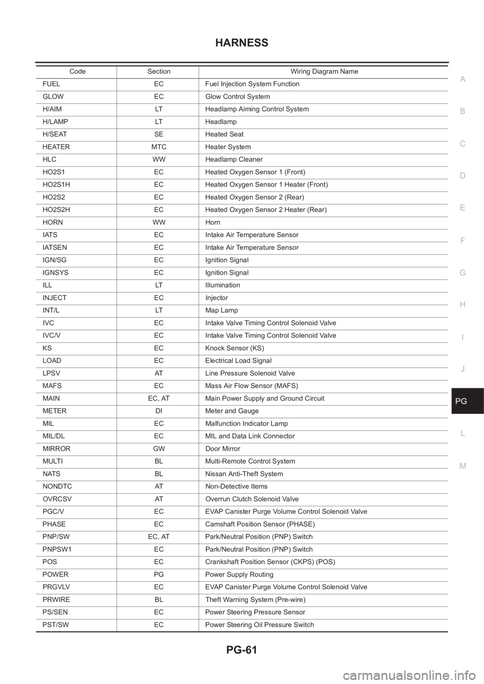
FUEL EC Fuel Injection System Function
GLOW EC Glow Control System
H/AIM LT Headlamp Aiming Control System
H/LAMP LT Headlamp
H/SEAT SE Heated Seat
HEATER MTC Heater System
HLC WW Headlamp Cleaner
HO2S1 EC Heated Oxygen Sensor 1 (Front)
HO2S1H EC Heated Oxygen Sensor 1 Heater (Front)
HO2S2 EC Heated Oxygen Sensor 2 (Rear)
HO2S2H EC Heated Oxygen Sensor 2 Heater (Rear)
HORN WW Horn
IATS EC Intake Air Temperature Sensor
IATSEN EC Intake Air Temperature Sensor
IGN/SG EC Ignition Signal
IGNSYS EC Ignition Signal
ILL LT Illumination
INJECT EC Injector
INT/L LT Map Lamp
IVC EC Intake Valve Timing Control Solenoid Valve
IVC/V EC Intake Valve Timing Control Solenoid Valve
KS EC Knock Sensor (KS)
LOAD EC Electrical Load Signal
LPSV AT Line Pressure Solenoid Valve
MAFS EC Mass Air Flow Sensor (MAFS)
MAIN EC, AT Main Power Supply and Ground Circuit
METER DI Meter and Gauge
MIL EC Malfunction Indicator Lamp
MIL/DL EC MIL and Data Link Connector
MIRROR GW Door Mirror
MULTI BL Multi-Remote Control System
NATS BL Nissan Anti-Theft System
NONDTC AT Non-Detective Items
OVRCSV AT Overrun Clutch Solenoid Valve
PGC/V EC EVAP Canister Purge Volume Control Solenoid Valve
PHASE EC Camshaft Position Sensor (PHASE)
PNP/SW EC, AT Park/Neutral Position (PNP) Switch
PNPSW1 EC Park/Neutral Position (PNP) Switch
POS EC Crankshaft Position Sensor (CKPS) (POS)
POWER PG Power Supply Routing
PRGVLV EC EVAP Canister Purge Volume Control Solenoid Valve
PRWIRE BL Theft Warning System (Pre-wire)
PS/SEN EC Power Steering Pressure Sensor
PST/SW EC Power Steering Oil Pressure SwitchCode Section Wiring Diagram Name