2001 NISSAN X-TRAIL key
[x] Cancel search: keyPage 3692 of 3833
AV-4
AUDIO
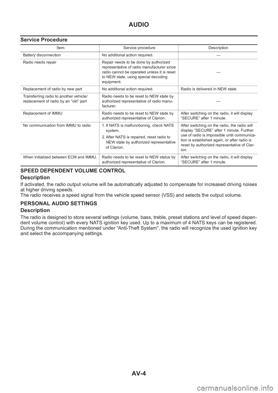
Service Procedure
SPEED DEPENDENT VOLUME CONTROL
Description
If activated, the radio output volume will be automatically adjusted to compensate for increased driving noises
at higher driving speeds.
The radio receives a speed signal from the vehicle speed sensor (VSS) and selects the output volume.
PERSONAL AUDIO SETTINGS
Description
The radio is designed to store several settings (volume, bass, treble, preset stations and level of speed depen-
dent volume control) with every NATS ignition key used. Up to a maximum of 4 NATS keys can be registered.
During the communication mentioned under “Anti-Theft System”, the radio will recognize the used ignition key
and select the accompanying settings.
Item Service procedure Description
Battery disconnection No additional action required. —
Radio needs repair Repair needs to be done by authorized
representative of radio manufacturer since
radio cannot be operated unless it is reset
to NEW state, using special decoding
equipment.—
Replacement of radio by new part No additional action required. Radio is delivered in NEW state.
Transferring radio to another vehicle/
replacement of radio by an “old” partRadio needs to be reset to NEW state by
authorized representative of radio manu-
facturer.—
Replacement of IMMU Radio needs to be reset to NEW state by
authorized representative of Clarion.After switching on the radio, it will display
“SECURE” after 1 minute.
No communication from IMMU to radio 1. If NATS is malfunctioning, check NATS
system.
2. After NATS is repaired, reset radio to
NEW state by authorized representative
of Clarion.After switching on the radio, the radio will
display “SECURE” after 1 minute. Further
use of radio is impossible until communica-
tion is established again, or after radio is
reset by authorized representative of Clar-
ion.
When initialized between ECM and IMMU. Radio needs to be reset to NEW status by
authorized representative of Clarion.After switching on the radio, it will display
“SECURE” after 1 minute.
Page 3784 of 3833
MA-4
DESCRIPTION
DESCRIPTION
PFP:00000
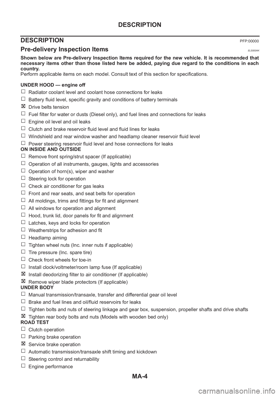
Pre-delivery Inspection ItemsELS000AK
Shown below are Pre-delivery Inspection Items required for the new vehicle. It is recommended that
necessary items other than those listed here be added, paying due regard to the conditions in each
country.
Perform applicable items on each model. Consult text of this section for specifications.
UNDER HOOD — engine off
Radiator coolant level and coolant hose connections for leaks
Battery fluid level, specific gravity and conditions of battery terminals
Drive belts tension
Fuel filter for water or dusts (Diesel only), and fuel lines and connections for leaks
Engine oil level and oil leaks
Clutch and brake reservoir fluid level and fluid lines for leaks
Windshield and rear window washer and headlamp cleaner reservoir fluid level
Power steering reservoir fluid level and hose connections for leaks
ON INSIDE AND OUTSIDE
Remove front spring/strut spacer (If applicable)
Operation of all instruments, gauges, lights and accessories
Operation of horn(s), wiper and washer
Steering lock for operation
Check air conditioner for gas leaks
Front and rear seats, and seat belts for operation
All moldings, trims and fittings for fit and alignment
All windows for operation and alignment
Hood, trunk lid, door panels for fit and alignment
Latches, keys and locks for operation
Weatherstrips for adhesion and fit
Headlamp aiming
Tighten wheel nuts (Inc. inner nuts if applicable)
Tire pressure (Inc. spare tire)
Check front wheels for toe-in
Install clock/voltmeter/room lamp fuse (If applicable)
Install deodorizing filter to air conditioner (If applicable)
Remove wiper blade protectors (If applicable)
UNDER BODY
Manual transmission/transaxle, transfer and differential gear oil level
Brake and fuel lines and oil/fluid reservoirs for leaks
Tighten bolts and nuts of steering linkage and gear box, suspension, propeller shafts and drive shafts
Tighten rear body bolts and nuts (Models with wooden bed only)
ROAD TEST
Clutch operation
Parking brake operation
Service brake operation
Automatic transmission/transaxle shift timing and kickdown
Steering control and returnability
Engine performance
Page 3830 of 3833
IDX-6
ALPHABETICAL INDEX
EC-181,EC-536,EC-862,EC-901,EC-908,EC-917,
EC-1231
HO2S2 - Wiring diagram .... EC-187,EC-195,EC-310,
EC-318
,EC-923,EC-930,EC-1038,EC-1045
HO2S2H - Wiring diagram ................. EC-135,EC-867
Hood .................................................................... BL-4
Horn ................................................................. WW-23
HORN - Wiring diagram ................................... WW-23
How to erase DTC ......................................... EC-1406
How to erase DTC for OBD system .... EC-56,EC-455,
EC-788
,EC-1142
I
IATS - Wiring diagram ....................... EC-146
,EC-878
IATSEN - Wiring diagram ................ EC-668,EC-1317
Identification ..................................................... ATC-12
Idle air volume learning ........ EC-39,EC-450,EC-772,
EC-1137
Idle speed EC-73,EC-465,EC-805,EC-1152,EC-1412
IGN/SG - Wiring diagram ................. EC-380,EC-1075
Ignition coil ........ EC-379,EC-683,EC-1074,EC-1331
Ignition coil(QR20DE•QR25DE) ....................... EM-29
Ignition control system ..... EC-379,EC-683,EC-1074,
EC-1331
Ignition timing ........ EC-73,EC-465,EC-805,EC-1152
IGNSYS - Wiring diagram ................ EC-684,EC-1332
ILL - Wiring diagram ........................................... LT-45
Illumination .......................................................... LT-45
In vehicle sensor ........... ATC-102,ATC-104,ATC-113
INJECT - Wiring diagram . EC-389,EC-710,EC-1084,
EC-1358
,EC-1475
Injection nozzle(YD22DDTi) ........................... EM-144
Injector .............. EC-388,EC-709,EC-1083,EC-1357
Input shaft (FF M/T) .............................. MT-18,MT-23
Instrument panel ................................................... IP-3
INT/L - Wiring diagram ........................................ LT-65
Intake air temperature sensor ........... EC-144,EC-160,
EC-667
,EC-876,EC-1316
Intake door control linkage adjustment ............ ATC-69
Intake door motor ATC-68,ATC-119,MTC-11,MTC-23
Intake manifold(QR20DE•QR25DE) ................. EM-16
Intake manifold(YD22DDTi) ............................ EM-123
Intake sensor ................................ ATC-108,ATC-115
Intake valve timing control . EC-125,EC-699,EC-857,
EC-1347
Intake valve timing control solenoid valve ...... EC-271,
EC-699
,EC-1005,EC-1347
Interior ....................... EI-23,EI-25,EI-26,EI-28,EI-29
Interior lamp ........................................................ LT-55
Interior lamp on-off control ...................... LT-55,LT-56
ISO 15031-5 Mode 1 - 9 ...................... EC-44,EC-777
IVC - Wiring diagram ....................... EC-273,EC-1007
IVC/V - Wiring diagram .................... EC-701,EC-1349
J
Joint connector (J/C) ............................. PG-70
,PG-74
K
Keyless entry system - See Multi-remote control system
BL-55
Knock sensor (KS) EC-222,EC-546,EC-951,EC-1235
KS - Wiring diagram ........... EC-224,EC-548,EC-953,
EC-1237
L
LAN system circuit .......................................... ATC-59
License lamp ...................................................... LT-30
Line pressure solenoid valve ........................... AT-156
Line pressure test (A/T) ....................... AT-67,AT-268
Liquid gasket application(QR20DE•QR25DE) ... EM-6,
EM-111
,LU-3,LU-15,CO-3,CO-23
LOAD - Wiring diagram .... EC-416,EC-737,EC-1103,
EC-1377
Location of electrical units ................................ PG-63
Lock, door ............................................... BL-65,BL-68
Lubricant (R134a) A/C ........................ ATC-5,ATC-24
Lubrication circuit (engine)(QR20DE•QR25DE) .. LU-5
Lubrication circuit (engine)(YD22DDTi) ............. LU-17
Lubrication oil A/C ......................................... ATC-150
Lubrication-locks, hinges and hood latches ...... MA-41
M
M/T major overhaul ............................... MT-26
,MT-35
M/T oil replacement .......................................... MT-10
M/T removal and installation ............................. MT-15
MAFS - Wiring diagram ..... EC-140,EC-519,EC-872,
EC-1001
,EC-1205,EC-1453
Magnet clutch ................................. ATC-78,ATC-135
MAIN - Wiring diagram ...... EC-116,EC-507,EC-848,
EC-1193
,EC-1443
Mainshaft (M/T) ..................................... MT-18,MT-23
Maintenance (engine)(QR20DE•QR25DE) ....... MA-19
Maintenance (engine)(YD22DDTi) ................... MA-26
Malfunction indicator (MI) .. EC-263,EC-576,EC-991,
EC-1265
,EC-1407
Malfunction indicator lamp (MIL) ........ EC-58,EC-457,
EC-790
,EC-1144
Mass air flow sensor (MAFS) ........... EC-138,EC-516,
EC-870
,EC-999,EC-1202,EC-1451
Master cylinder (brake) ...................................... BR-13
Master cylinder (clutch) ........................................ CL-9
METER - Wiring diagram ........................... DI-8,DI-28
MIL - Wiring diagram ......... EC-264,EC-577,EC-992,
EC-1266
MIL/DL - Wiring diagram ................................ EC-1573
MIRROR - Wiring diagram ............................... GW-50
Mirror defogger ................................................ GW-15
Mirror, door ...................................................... GW-49
Mirror, out side ................................................. GW-49
Misfire ............................................... EC-217,EC-946
Mode door control linkage adjustment ........... ATC-64,
ATC-124
,MTC-9,MTC-27
Mode door motor ............................ ATC-62,ATC-124