2001 NISSAN X-TRAIL sensor
[x] Cancel search: sensorPage 2661 of 3833
TROUBLE DIAGNOSIS
TF-51
C
E
F
G
H
I
J
K
L
MA
B
TF
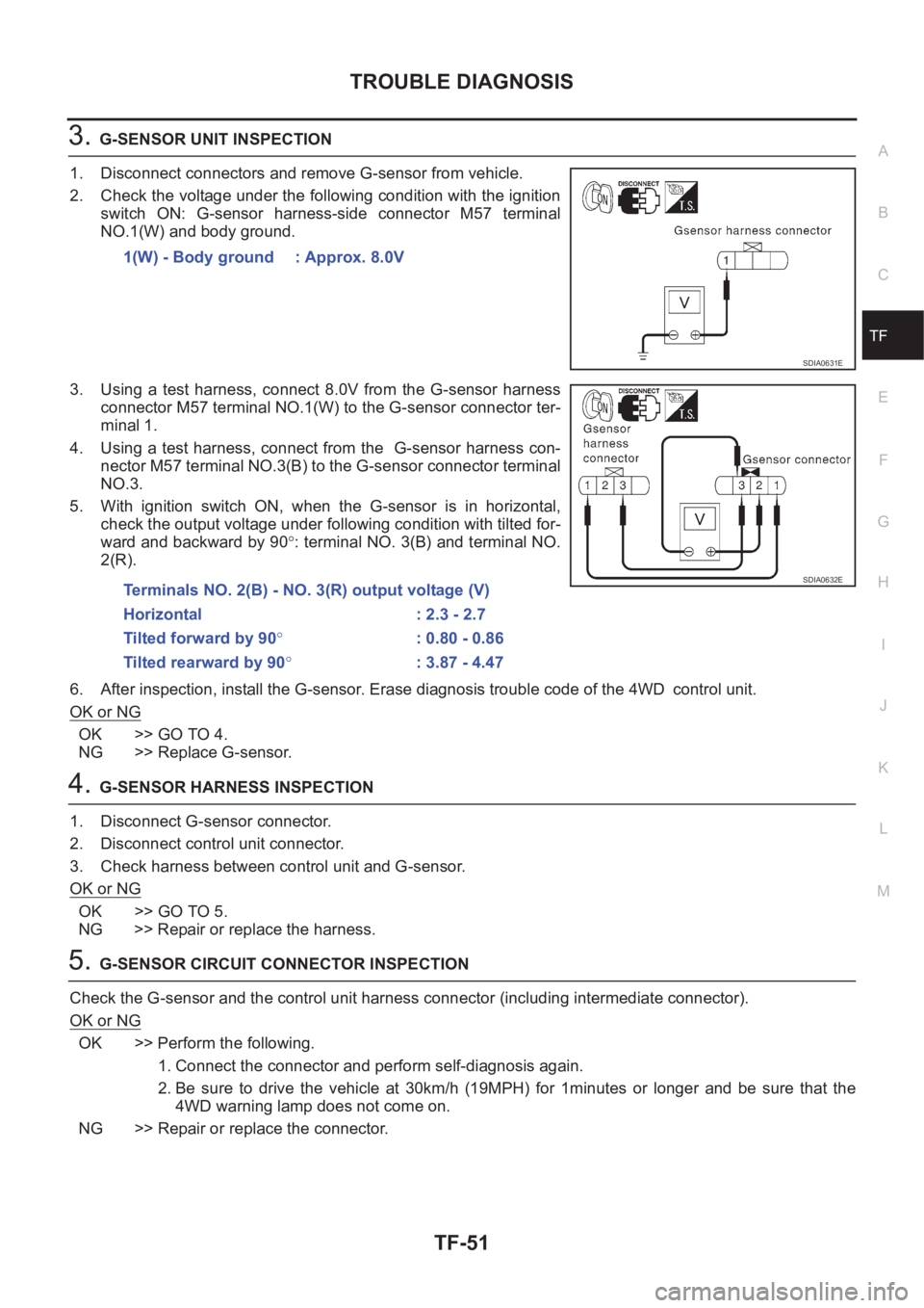
3.G-SENSOR UNIT INSPECTION
1. Disconnect connectors and remove G-sensor from vehicle.
2. Check the voltage under the following condition with the ignition
switch ON: G-sensor harness-side connector M57 terminal
NO.1(W) and body ground.
3. Using a test harness, connect 8.0V from the G-sensor harness
connector M57 terminal NO.1(W) to the G-sensor connector ter-
minal 1.
4. Using a test harness, connect from the G-sensor harness con-
nector M57 terminal NO.3(B) to the G-sensor connector terminal
NO.3.
5. With ignition switch ON, when the G-sensor is in horizontal,
check the output voltage under following condition with tilted for-
ward and backward by 90°: terminal NO. 3(B) and terminal NO.
2(R).
6. After inspection, install the G-sensor. Erase diagnosis trouble code of the 4WD control unit.
OK or NG
OK >> GO TO 4.
NG >> Replace G-sensor.
4.G-SENSOR HARNESS INSPECTION
1. Disconnect G-sensor connector.
2. Disconnect control unit connector.
3. Check harness between control unit and G-sensor.
OK or NG
OK >> GO TO 5.
NG >> Repair or replace the harness.
5.G-SENSOR CIRCUIT CONNECTOR INSPECTION
Check the G-sensor and the control unit harness connector (including intermediate connector).
OK or NG
OK >> Perform the following.
1. Connect the connector and perform self-diagnosis again.
2. Be sure to drive the vehicle at 30km/h (19MPH) for 1minutes or longer and be sure that the
4WD warning lamp does not come on.
NG >> Repair or replace the connector.1(W) - Body ground : Approx. 8.0V
SDIA0631E
Terminals NO. 2(B) - NO. 3(R) output voltage (V)
Horizontal : 2.3 - 2.7
Tilted forward by 90°: 0.80 - 0.86
Tilted rearward by 90°: 3.87 - 4.47SDIA0632E
Page 2668 of 3833
TF-58
TROUBLE DIAGNOSIS
●Perform inspection with the data monitor function of the CONSULT- I I .
●Check if the value of IMPROPER SIZE TIRE MONITOR is 8 mm (0.31 in) or more.
●Stop the engine. Restart the engine and drive the vehicle at 20 km/h (12 MPH) or faster for approxi-
mately 200 seconds. Confirm the 4WD warning lamp flashes slowly.
(Check if the value of IMPROPER SIZE TIRE MONITOR is 8 mm (0.31 in) or more.)
When the tire size is normal, the value of IMPROPER SIZE TIRE MONITOR will change from 8 mm
(0.31 in) or more to 0 to 4 mm (0 to 0.16 in) (normal condition) after the vehicle is driven 20 km/h (12
MPH) or faster for approximately 5 seconds.
2. Tire inspection
●Inspection of tire pressure.
●Wear condition.
●Check size of the front and rear tires. (No excessive difference should be observed.)
VEHICLE DOES NOT ENTER 4WD MODE EVEN THOUGH 4WD WARNING LAMP IS OFF.
1. Check using the data monitor function of the CONSULT-II.
Perform inspection by the data monitor function of the CONSULT-II.
–Check if the vehicle operation changes to 2WD, AUTO, and LOCK modes.
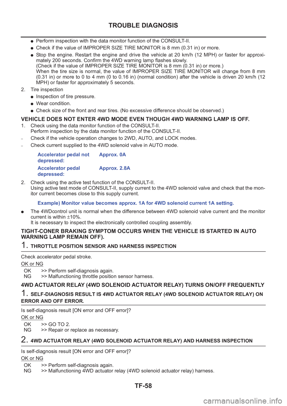
–Check current supplied to the 4WD solenoid valve in AUTO mode.
2. Check using the active test function of the CONSULT-II.
Using active test mode of CONSULT-II, supply current to the 4WD solenoid valve and check that the mon-
itor current becomes close to this supply current.
●The 4WDcontrol unit is normal when the difference between 4WD solenoid valve current and the monitor
current is within ±10%.
It is necessary to inspect the electronically controlled coupling assembly.
TIGHT-CONER BRAKING SYMPTOM OCCURS WHEN THE VEHICLE IS STARTED IN AUTO
WARNING LAMP REMAIN OFF).
1. THROTTLE POSITION SENSOR AND HARNESS INSPECTION
Check accelerator pedal stroke.
OK or NG
OK >> Perform self-diagnosis again.
NG >> Malfunctioning throttle position sensor harness.
4WD ACTUATOR RELAY (4WD SOLENOID ACTUATOR RELAY) TURNS ON/OFF FREQUENTLY
1. SELF-DIAGNOSIS RESULT IS 4WD ACTUATOR RELAY (4WD SOLENOID ACTUATOR RELAY) ON
ERROR AND OFF ERROR.
Is self-diagnosis result [ON error and OFF error]?
OK or NG
OK >> GO TO 2.
NG >> Repair or replace as necessary.
2. 4WD ACTUATOR RELAY (4WD SOLENOID ACTUATOR RELAY) AND HARNESS INSPECTION
Is self-diagnosis result [ON error and OFF error]?
OK or NG
OK >> Perform self-diagnosis again.
NG >> Malfunctioning 4WD actuator relay (4WD solenoid actuator relay) harness. Accelerator pedal not
depressed:Approx. 0A
Accelerator pedal
depressed:Approx. 2.8A
Example) Monitor value becomes approx. 1A for 4WD solenoid current 1A setting.
Page 2714 of 3833
FSU-8
COIL SPRING AND SHOCK ABSORBER
COIL SPRING AND SHOCK ABSORBER
PFP:54302
Removal and InstallationEES00074
REMOVAL
1. Remove tires. Remove brake caliper and hung it aside.
CAUTION:
Avoid depressing brake pedal with brake caliper removed.
2. Remove electrical wires of ABS wheel speed sensor from strut.
3. Remove brake hose lock plate.
4. Remove mounting bolts and nuts securing steering knuckle to strut.
5. Remove mounting nuts on upper mounting plate and remove upper mounting plate and strut from vehicle.
INSTALLATION
●Refer to FSU-5, "Components" in “Front Suspension Assembly” for tightening torque. Tighten in the
reverse order of removal.
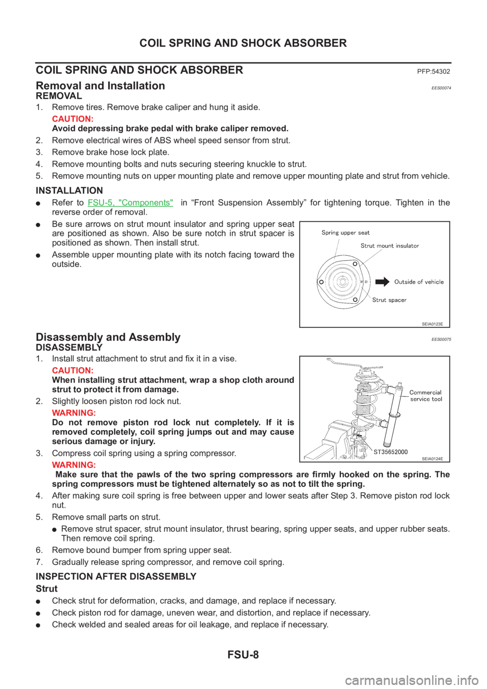
●Be sure arrows on strut mount insulator and spring upper seat
are positioned as shown. Also be sure notch in strut spacer is
positioned as shown. Then install strut.
●Assemble upper mounting plate with its notch facing toward the
outside.
Disassembly and AssemblyEES00075
DISASSEMBLY
1. Install strut attachment to strut and fix it in a vise.
CAUTION:
When installing strut attachment, wrap a shop cloth around
strut to protect it from damage.
2. Slightly loosen piston rod lock nut.
WARNING:
Do not remove piston rod lock nut completely. If it is
removed completely, coil spring jumps out and may cause
serious damage or injury.
3. Compress coil spring using a spring compressor.
WARNING:
Make sure that the pawls of the two spring compressors are firmly hooked on the spring. The
spring compressors must be tightened alternately so as not to tilt the spring.
4. After making sure coil spring is free between upper and lower seats after Step 3. Remove piston rod lock
nut.
5. Remove small parts on strut.
●Remove strut spacer, strut mount insulator, thrust bearing, spring upper seats, and upper rubber seats.
Then remove coil spring.
6. Remove bound bumper from spring upper seat.
7. Gradually release spring compressor, and remove coil spring.
INSPECTION AFTER DISASSEMBLY
Strut
●Check strut for deformation, cracks, and damage, and replace if necessary.
●Check piston rod for damage, uneven wear, and distortion, and replace if necessary.
●Check welded and sealed areas for oil leakage, and replace if necessary.
SEIA0123E
SEIA0124E
Page 2730 of 3833
RSU-10
FRONT PARALLEL LINK
FRONT PARALLEL LINK
PFP:55120
Removal and InstallationEES0007J
REMOVAL
1. Remove tires, Raise vehicle.
2. Remove ABS wheel speed sensor wire (With ABS models).
3. Remove front parallel link mounting bolts and nuts. Remove front parallel link from vehicle.
INSPECTION AFTER REMOVAL
●Replace front parallel link assembly if it is in following condition: deformed, cracked, or damaged, or if the
bushing was damaged.
INSTALLATION
●Refer to RSU-5, "Components" for tightening torque and reverse the removal procedure for installation.
Page 2733 of 3833
REAR SUSPENSION MEMBER
RSU-13
C
D
F
G
H
I
J
K
L
MA
B
RSU
REAR SUSPENSION MEMBERPFP:55501
Removal and InstallationEES0007M
REMOVAL
1. Remove tires. Raise vehicle.
2. Remove cotter pin. Remove wheel hub lock nut by using a wheel hub lock nut wrench.
3. Remove ABS wheel speed sensor and wiring (With ABS models).
4. Remove brake caliper and brake hose lock plate, and hang them aside.
5. Remove mounting bolts and nuts on lower portion of strut.
6. Remove axle-side mounting bolts of parallel link and remove rear drive shaft from axle housing.
7. Remove suspension member-side mounting bolt of parallel link and remove parallel link from suspension
member.
8. Remove mounting bolts and nuts on lower portion of strut.
CAUTION:
After removing drive shaft, position axle housing onto strut.
9. Remove propeller shaft.
10. Remove rear exhaust tube.
11. Remove electronically controlled coupling connector and air breather hose from final drive.
12. Set a transmission jack under rear final drive.
13. Remove front and rear mounting bolts from rear final drive.
14. Remove rear final drive from suspension member.
15. Place transmission jack onto rear suspension member. Remove rear suspension member mounting bolts.
Lower transmission jack slowly to remove rear suspension member from vehicle.
INSTALLATION
●Refer to RSU-5, "Components" for tightening torque. Install in the reverse order of removal.
●After installation, perform final tightening of each part under unladen conditions with tires on ground.
Check wheel alignment.RSU-6, "
Wheel Alignment" .
Page 2753 of 3833
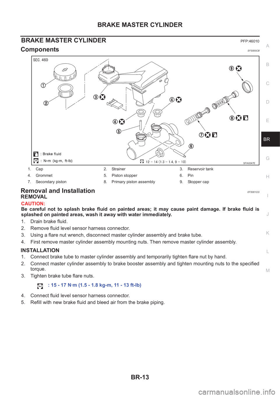
BRAKE MASTER CYLINDER
BR-13
C
D
E
G
H
I
J
K
L
MA
B
BR
BRAKE MASTER CYLINDERPFP:46010
ComponentsEFS000CB
Removal and InstallationEFS001CG
REMOVAL
CAUTION:
Be careful not to splash brake fluid on painted areas; it may cause paint damage. If brake fluid is
splashed on painted areas, wash it away with water immediately.
1. Drain brake fluid.
2. Remove fluid level sensor harness connector.
3. Using a flare nut wrench, disconnect master cylinder assembly and brake tube.
4. First remove master cylinder assembly mounting nuts. Then remove master cylinder assembly.
INSTALLATION
1. Connect brake tube to master cylinder assembly and temporarily tighten flare nut by hand.
2. Connect master cylinder assembly to brake booster assembly and tighten mounting nuts to the specified
torque.
3. Tighten brake tube flare nuts.
4. Connect fluid level sensor harness connector.
5. Refill with new brake fluid and bleed air from the brake piping.
1. Cap 2. Strainer 3. Reservoir tank
4. Grommet 5. Piston stopper 6. Pin
7. Secondary piston 8. Primary piston assembly 9. Stopper cap
SFIA0047E
: 15 - 17 N·m (1.5 - 1.8 kg-m, 11 - 13 ft-lb)
Page 2785 of 3833
BRC-1
BRAKE CONTROL SYSTEM
F BRAKES
CONTENTS
C
D
E
G
H
I
J
K
L
M
SECTION
A
B
BRC
BRAKE CONTROL SYSTEM
4WD/ABS
PRECAUTIONS .......................................................... 4
Precautions for brake system ................................... 4
Precautions for brake control ................................... 4
PREPARATION ........................................................... 5
Special Service Tool ................................................. 5
Commercial Service Tool ......................................... 5
ALL MODE 4X4 SYSTEM .......................................... 6
System Description .................................................. 6
ABS FUNCTION ................................................... 6
4WD FUNCTION ................................................... 6
Control System Diagram .......................................... 6
TROUBLE DIAGNOSIS .............................................. 7
Fail-safe Function ..................................................... 7
How to Proceed with Trouble Diagnosis .................. 7
BASIC CONCEPT ................................................. 7
DIAGNOSIS FLOW ............................................... 8
ASKING COMPLAINTS ........................................ 9
TROUBLE DIAGNOSIS SHEET - EXAMPLE ....... 9
Component Parts Location ..................................... 10
Schematic ............................................................... 11
Wiring Diagram — ABS — ..................................... 12
Trouble Diagnosis Chart by Symptom .................... 18
4WD/ABS Control Unit Input/Output Signal Stan-
dard ........................................................................ 19
4WD/ABS CONTROL UNIT CONNECTOR TER-
MINAL ARRANGEMENT .................................... 19
REFERENCE STANDARD TABLE ..................... 19
CONSULT-II Functions ........................................... 23
CONSULT-II FUNCTION APPLICATION TABLE ... 23
SELF-DIAGNOSIS .............................................. 24
DATA MONITOR ................................................. 26
ACTIVE TEST ..................................................... 29
Component Inspection ........................................... 30
ABS ACTUATOR ................................................ 30
4WD SOLENOID VALVE .................................... 32
Basic Inspection ..................................................... 32
BASIC INSPECTION 1 BRAKE FLUID LEVEL
AND LEAKAGE INSPECTION ............................ 32
BASIC INSPECTION 2 INSPECTION FOR LOOSE POWER SUPPLY TERMINAL ............... 32
BASIC INSPECTION 3 ABS/4WD WARNING
LAMP INSPECTION ............................................ 32
Wheel Sensor System ............................................ 32
INSPECTION PROCEDURE .............................. 32
Control Unit Power Supply System ........................ 34
INSPECTION PROCEDURE .............................. 34
G -Sensor System (4WD models) .......................... 34
INSPECTION PROCEDURE .............................. 34
4WD Solenoid, Actuator Relay System .................. 35
4WD Mode Switch System ..................................... 37
Trouble Diagnoses for Symptoms .......................
... 38
4WD INDICATOR LAMP DOES NOT COME ON
FOR APPROXIMATELY 1 SECOND WHEN THE
IGNITION SWITCH IS TURNED TO ON ............. 38
4WD WARNING LAMP DOES NOT ILLUMINATE
WITH IGNITION ON ............................................ 39
4WD WARNING LAMP DOES NOT GO OUT
SEVERAL SECONDS AFTER ENGINE
STARTED.(4WD MODE INDICATOR LAMP
GOES OUT) ........................................................ 39
HEAVY TIGHT-CORNER BRAKING SYMPTOM
OCCURS WHEN THE VEHICLE IS DRIVEN IN
AUTO MODE AND THE STEERING WHEEL IS
TURNED FULLY TO EITHER SIDE AFTER THE
ENGINE IS STARTED ......................................... 39
4WD MODES CANNOT BE SWITCHED AFTER
ENGINE IS STARTED ......................................... 41
WHILE DRIVING, 4WD WARNING LAMP
FLASHES RAPIDLY. (WHEN IT FLASHERS FOR
APPROX. ONE MINUTE, THEN DOES NOT
ILLUMINATE.) ..................................................... 41
WHILE DRIVING, 4WD WARNING LAMP
FLASHES SLOWLY. (WHEN IT CONTINUES TO
ILLUMINATE UNTIL ENGINE TURNS OFF.) ...... 41
VEHICLE DOES NOT ENTER 4WD MODE
EVEN THOUGH 4WD WARNING LAMP IS OFF. ... 41
TIGHT-CORNER BRAKING SYMPTOM
OCCURS WHEN THE VEHICLE IS STARTED IN
AUTO WARNING LAMP REMAIN OFF). ............ 42
Page 2786 of 3833
BRC-2
4WD ACTUATOR RELAY (4WD SOLENOID
A C T U AT O R R E L AY ) T U R N S O N / O F F F R E -
QUENTLY ............................................................ 42
ABS Warning Lamp Does Not Illuminate. (ABS
Warning Lamp Does Not Come On When The Igni-
tion Switch Is Turned ON.) ...................................... 42
ABS Warning Lamp Illuminates With Ignition ON,
But Does Not Illuminates After A Few Seconds.
(ABS Warning Lamp Has Illuminated.) ................... 42
4WD Warning Lamp Does Not Illuminate With Igni-
tion ON. .................................................................. 43
4WD Warning Lamp Does Not Go Out Several Sec-
onds After Engine Is Started. (Drive Mode Indicator
Lamp Goes Out.) .................................................... 43
Heavy Tight-corner Braking Symptom Occurs
When The Vehicle Is Driven In Auto Mode And The
Steering Wheel Is Turned Fully To Either Side After
The Engine Is Started. ............................................ 44
Drive Modes Cannot Be Switched After Engine Is
Started. ................................................................... 45
Wheel Driving, 4WD Warning Lamp Flashes Rap-
idly. (When It Flashes For Approx. One Minute, Then
Does Not Illuminate.) .............................................. 45
Wheel Driving, 4WD Warning Lamp Flashes Slowly.
(When It Continues To Illuminate Until Engine Turns
OFF.) ....................................................................... 45
Vehicle Does Not Enter 4WD Mode Even Though
4WD Warning Lamp Is OFF. ................................... 46
Tight-corner Braking Symptom Occurs When The
Vehicle Is Started In Auto Mode (4WD Warning
Lamp Remain OFF). ............................................... 46
E-TS Actuator Relay (4WD Solenoid Actuator
Relay) Turns ON/OFF Frequently. .......................... 46
Inspection Of Drive Mode Change-over Switch Path ... 47
4WD/ABS CONTROL UNIT ...................................... 48
Removal and Installation ........................................ 48
REMOVAL ........................................................... 48
INSTALLATION .................................................... 48
WHEEL SENSORS ................................................... 49
Removal and Installation ........................................ 49
G-SENSOR (4WD MODEL ONLY) ............................ 50
Removal and Installation ........................................ 50
SENSOR ROTOR ................................................... ... 51
Removal and Installation ........................................ 51
REMOVAL ........................................................... 51
INSTALLATION .................................................... 51
ACTUATOR ............................................................... 52
Removal and Installation ........................................ 52
REMOVAL ........................................................... 53
INSTALLATION .................................................... 53
ESP/TCS/ABS
PRECAUTIONS ......................................................... 54
Precautions for Brake System ................................ 54
Precautions for Brake Control ................................ 54
Precautions for CAN System .................................. 54
FOR INSPECTION .............................................. 54
FOR HARNESS REPAIR .................................... 55PREPARATION ......................................................... 56
Special Service Tool ................................................ 56
Commercial Service Tool ........................................ 56
ON-VEHICLE SERVICE ............................................ 57
Adjustment of Neutral Position of Steering Wheel
Angle Sensor .......................................................... 57
GENERAL INFORMATION ....................................... 59
Fail-Safe .................................................................. 59
ABS SYSTEM ...................................................... 59
ESP/TCS SYSTEM .............................................. 59
Hydraulic Circuit ...................................................... 59
ABS Functions ........................................................ 59
TCS Functions ........................................................ 60
ESP Functions ........................................................ 60
System Diagram ..................................................... 61
CAN COMMUNICATION ........................................... 62
System Description ................................................. 62
FOR A/T MODELS ............................................... 62
FOR M/T MODELS .............................................. 62
TROUBLE DIAGNOSIS ............................................ 64
How to Perform Trouble Diagnoses for Quick and
Accurate Repair ...................................................... 64
INTRODUCTION ................................................. 64
WORK FLOW ...................................................... 65
ASKING COMPLAINTS ....................................... 66
EXAMPLE OF DIAGNOSIS SHEET .................... 66
Component Parts and Harness Connector Location ... 67
Schematic ............................................................... 68
Wiring Diagram —ESP/TCS/ABS— ..................... 69
Control Unit Input/Output Signal Standard .............. 75
STANDARDS USING A CIRCUIT TESTER AND
OSCILLOSCOPE ................................................. 75
STANDARDS WITH CONSULT-II ........................ 78
Functions of CONSULT-II ....................................... 80
CONSULT-II MAINLY FUNCTION APPLICA-
TION TO ESP/TCS/ABS ...................................... 80
SELF-DIAGNOSIS ............................................... 81
DATA MONITOR .................................................. 83
ACTIVE TEST ...................................................... 87
For Correct and Quick Diagnosis ............................ 90
PRECAUTIONS FOR TROUBLE DIAGNOSIS ... 90
Basic Inspection ...................................................... 91
PRELIMINARY CHECK 1: (BRAKE FLUID
LEVEL AND LEAK INSPECTION) ....................... 91
PRELIMINARY CHECK 2: (INSPECTION FOR
LOOSE POWER SUPPLY TERMINAL) ............... 92
PRELIMINARY CHECK 3: (INSPECTION FOR
ABS WARNING LAMP, ESP OFF INDICATOR
LAMP, AND SLIP INDICATOR LAMP) ................. 92
Inspection 1 Wheel Sensor and Circuit ................... 92
Inspection 2 Engine System ................................... 94
Inspection 3 ESP/TCS/ABS Control Unit System ... 94
Inspection 4 Pressure Sensor and the Circuit
between Pressure Sensor and ESP/TCS/ABS Con-
trol Unit. ................................................................... 95
Inspection 5 Steering wheel Angle Sensor and the
Circuit between Steering Wheel Angle Sensor and
ESP/TCS/ABS Control Unit. ................................... 96
Inspection 6 Yaw Rate Sensor and Side G sensor