2001 NISSAN PICK-UP width
[x] Cancel search: widthPage 50 of 1306

Mixture Ratio Feedback Control (Closed loop control)NEEC0014S04
SEC303D
The mixture ratio feedback system provides the best air-fuel mixture ratio for driveability and emission con-
trol. The three way catalyst can then better reduce CO, HC and NOx emissions. This system uses a heated
oxygen sensor 1 in the exhaust manifold to monitor if the engine operation is rich or lean. The ECM adjusts
the injection pulse width according to the sensor voltage signal. For more information about the heated oxy-
gen sensor 1, refer to EC-3213. This maintains the mixture ratio within the range of stoichiometric (ideal air-
fuel mixture).
This stage is referred to as the closed loop control condition.
Heated oxygen sensor 2 is located downstream of the three way catalyst. Even if the switching characteris-
tics of the heated oxygen sensor 1 shift, the air-fuel ratio is controlled to stoichiometric by the signal from the
heated oxygen sensor 2.
Open Loop ControlNEEC0014S05The open loop system condition refers to when the ECM detects any of the following conditions. Feedback
control stops in order to maintain stabilized fuel combustion.
+Deceleration and acceleration
+High-load, high-speed operation
+Malfunction of heated oxygen sensor 1 or its circuit
+Insufficient activation of heated oxygen sensor 1 at low engine coolant temperature
+High engine coolant temperature
+During warm-up
+When starting the engine
Mixture Ratio Self-learning ControlNEEC0014S06The mixture ratio feedback control system monitors the mixture ratio signal transmitted from the heated oxy-
gen sensor 1. This feedback signal is then sent to the ECM. The ECM controls the basic mixture ratio as close
to the theoretical mixture ratio as possible. However, the basic mixture ratio is not necessarily controlled as
originally designed. Both manufacturing differences (i.e., mass air flow sensor hot film) and characteristic
changes during operation (i.e., injector clogging) directly affect mixture ratio.
Accordingly, the difference between the basic and theoretical mixture ratios is monitored in this system. This
is then computed in terms of ªinjection pulse durationº to automatically compensate for the difference between
the two ratios.
ªFuel trimº refers to the feedback compensation value compared against the basic injection duration. Fuel trim
includes short term fuel trim and long term fuel trim.
ªShort term fuel trimº is the short-term fuel compensation used to maintain the mixture ratio at its theoretical
value. The signal from the heated oxygen sensor 1 indicates whether the mixture ratio is RICH or LEAN com-
pared to the theoretical value. The signal then triggers a reduction in fuel volume if the mixture ratio is rich,
and an increase in fuel volume if it is lean.
ªLong term fuel trimº is overall fuel compensation carried out long-term to compensate for continual deviation
of the short term fuel trim from the central value. Such deviation will occur due to individual engine differences,
wear over time and changes in the usage environment.
ENGINE AND EMISSION BASIC CONTROL SYSTEM
DESCRIPTION
KA24DE (EURO OBD)
Multiport Fuel Injection (MFI) System
EC-3025
Page 51 of 1306

Fuel Injection TimingNEEC0014S07
SEF337W
Two types of systems are used.
Sequential Multiport Fuel Injection System
NEEC0014S0701Fuel is injected into each cylinder during each engine cycle according to the firing order. This system is used
when the engine is running.
Simultaneous Multiport Fuel Injection System
NEEC0014S0702Fuel is injected simultaneously into all four cylinders twice each engine cycle. In other words, pulse signals of
the same width are simultaneously transmitted from the ECM.
The four injectors will then receive the signals two times for each engine cycle.
This system is used when the engine is being started and/or if the fail-safe system (CPU) is operating.
Fuel Shut-offNEEC0014S08Fuel to each cylinder is cut off during deceleration or operation of the engine at excessively high speeds.
Distributor Ignition (DI) System
DESCRIPTIONNEEC0015Input/Output Signal ChartNEEC0015S01
Sensor Input Signal to ECMECM func-
tionActuator
Camshaft position sensor Engine speed and piston position
Ignition tim-
ing controlPower transistor Mass air flow sensor Amount of intake air
Engine coolant temperature sensor Engine coolant temperature
Throttle position sensorThrottle position
Throttle valve idle position
Vehicle speed sensor Vehicle speed
Ignition switch Start signal
Knock sensor Engine knocking
PNP switch Gear position
Battery Battery voltage
ENGINE AND EMISSION BASIC CONTROL SYSTEM
DESCRIPTION
KA24DE (EURO OBD)
Multiport Fuel Injection (MFI) System
EC-3026
Page 52 of 1306

System DescriptionNEEC0015S02
SEF742M
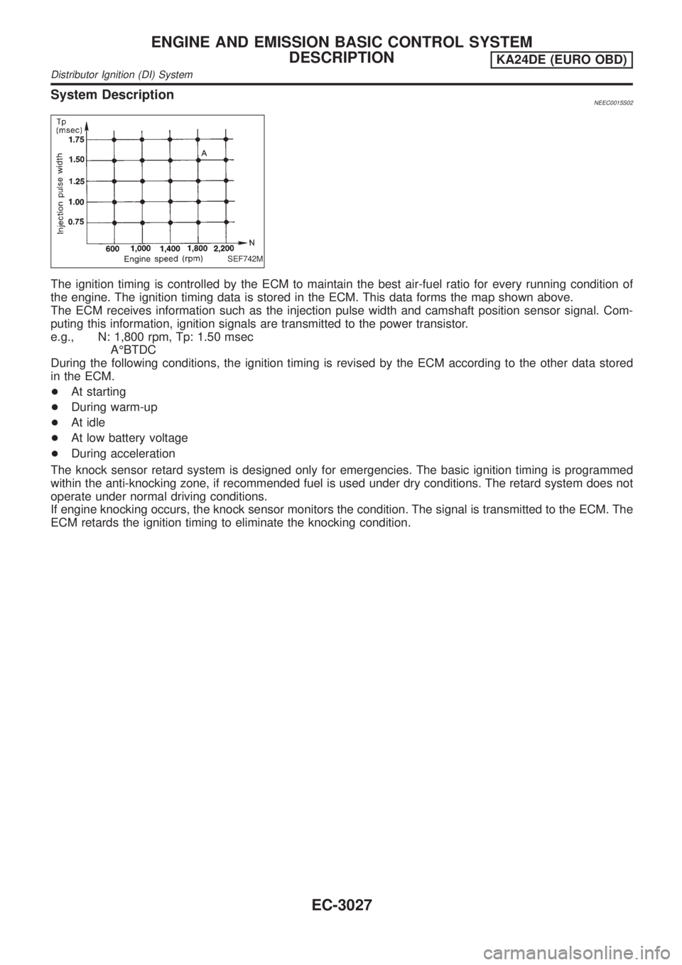
The ignition timing is controlled by the ECM to maintain the best air-fuel ratio for every running condition of
the engine. The ignition timing data is stored in the ECM. This data forms the map shown above.
The ECM receives information such as the injection pulse width and camshaft position sensor signal. Com-
puting this information, ignition signals are transmitted to the power transistor.
e.g., N: 1,800 rpm, Tp: 1.50 msec
AÉBTDC
During the following conditions, the ignition timing is revised by the ECM according to the other data stored
in the ECM.
+At starting
+During warm-up
+At idle
+At low battery voltage
+During acceleration
The knock sensor retard system is designed only for emergencies. The basic ignition timing is programmed
within the anti-knocking zone, if recommended fuel is used under dry conditions. The retard system does not
operate under normal driving conditions.
If engine knocking occurs, the knock sensor monitors the condition. The signal is transmitted to the ECM. The
ECM retards the ignition timing to eliminate the knocking condition.
ENGINE AND EMISSION BASIC CONTROL SYSTEM
DESCRIPTION
KA24DE (EURO OBD)
Distributor Ignition (DI) System
EC-3027
Page 99 of 1306
![NISSAN PICK-UP 2001 Repair Manual Freeze frame data
item*Description
INT/A TEMP SE [ÉC]
or [ÉF]+The intake air temperature at the moment a malfunction is detected is displayed.
*: The items are the same as those of 1st trip freeze f NISSAN PICK-UP 2001 Repair Manual Freeze frame data
item*Description
INT/A TEMP SE [ÉC]
or [ÉF]+The intake air temperature at the moment a malfunction is detected is displayed.
*: The items are the same as those of 1st trip freeze f](/manual-img/5/57372/w960_57372-98.png)
Freeze frame data
item*Description
INT/A TEMP SE [ÉC]
or [ÉF]+The intake air temperature at the moment a malfunction is detected is displayed.
*: The items are the same as those of 1st trip freeze frame data.
DATA MONITOR MODENEEC0034S06
Monitored item [Unit]ECM
input
signalsMain
signalsDescription Remarks
ENG SPEED [rpm]jj+Indicates the engine speed computed
from the REF signal (180É signal) of
the camshaft position sensor.+Accuracy becomes poor if engine
speed drops below the idle rpm.
+If the signal is interrupted while the
engine is running, an abnormal value
may be indicated.
MAS A/F SE-B1 [V]jj+The signal voltage of the mass air flow
sensor is displayed.+When the engine is stopped, a cer-
tain value is indicated.
B/FUEL SCHDL [msec]j+ªBase fuel scheduleº indicates the fuel
injection pulse width programmed into
ECM, prior to any learned on board
correction.
A/F ALPHA-B1 [%]j+Indicates the mean value of the air-fuel
ratio feedback correction factor per
cycle.+When the engine is stopped, a cer-
tain value is indicated.
+This data also includes the data for
the air-fuel ratio learning control.
COOLAN TEMP/S
[ÉC] or [ÉF]jj+The engine coolant temperature (deter-
mined by the signal voltage of the
engine coolant temperature sensor) is
displayed.+When the engine coolant temperature
sensor is open or short-circuited,
ECM enters fail-safe mode. The
engine coolant temperature deter-
mined by the ECM is displayed.
HO2S1 (B1) [V]jj+The signal voltage of the heated oxy-
gen sensor 1 is displayed.
HO2S2 (B1) [V]j+The signal voltage of the heated oxy-
gen sensor 2 is displayed.
HO2S1 MNTR (B1)
[RICH/LEAN]jj+Display of heated oxygen sensor 1 sig-
nal during air-fuel ratio feedback con-
trol:
RICH ... means the mixture became
ªrichº, and control is being affected
toward a leaner mixture.
LEAN ... means the mixture became
ªleanº, and control is being affected
toward a rich mixture.+After turning ON the ignition switch,
ªRICHº is displayed until air-fuel mix-
ture ratio feedback control begins.
+When the air-fuel ratio feedback is
clamped, the value just before the
clamping is displayed continuously.
HO2S2 MNTR (B1)
[RICH/LEAN]j+Display of heated oxygen sensor 2 sig-
nal:
RICH ... means the amount of oxygen
after three way catalyst is relatively
small.
LEAN ... means the amount of oxygen
after three way catalyst is relatively
large.+When the engine is stopped, a cer-
tain value is indicated.
VHCL SPEED SE
[km/h] or [mph]jj+The vehicle speed computed from the
vehicle speed sensor signal is dis-
played.
BATTERY VOLT [V]jj+The power supply voltage of ECM is
displayed.
ON BOARD DIAGNOSTIC SYSTEM
DESCRIPTION
KA24DE (EURO OBD)
CONSULT-II
EC-3074
Page 100 of 1306
![NISSAN PICK-UP 2001 Repair Manual Monitored item [Unit]ECM
input
signalsMain
signalsDescription Remarks
THRTL POS SEN [V]jj+The throttle position sensor signal volt-
age is displayed.
INT/A TEMP SE
[ÉC] or [ÉF]jj+The intake air temp NISSAN PICK-UP 2001 Repair Manual Monitored item [Unit]ECM
input
signalsMain
signalsDescription Remarks
THRTL POS SEN [V]jj+The throttle position sensor signal volt-
age is displayed.
INT/A TEMP SE
[ÉC] or [ÉF]jj+The intake air temp](/manual-img/5/57372/w960_57372-99.png)
Monitored item [Unit]ECM
input
signalsMain
signalsDescription Remarks
THRTL POS SEN [V]jj+The throttle position sensor signal volt-
age is displayed.
INT/A TEMP SE
[ÉC] or [ÉF]jj+The intake air temperature determined
by the signal voltage of the intake air
temperature sensor is indicated.
START SIGNAL
[ON/OFF]jj+Indicates [ON/OFF] condition from the
starter signal.+After starting the engine, [OFF] is dis-
played regardless of the starter sig-
nal.
CLSD THL POS
[ON/OFF]jj+Indicates idle position [ON/OFF] com-
puted by ECM according to the throttle
position sensor signal.
CLSD THL/P SW
[ON/OFF]j+Indicates mechanical contact [ON/OFF]
condition of the closed throttle position
switch.
AIR COND SIG
[ON/OFF]jj+Indicates [ON/OFF] condition of the air
conditioner switch as determined by
the air conditioning signal.
P/N POSI SW
[ON/OFF]jj+Indicates [ON/OFF] condition from the
PNP switch signal.
PW/ST SIGNAL
[ON/OFF]jj+Indicates [ON/OFF] condition of the
power steering oil pressure switch
determined by the power steering oil
pressure switch signal.
AMB TEMP SW
[ON/OFF]j+Indicates [ON/OFF] condition from the
ambient air temperature switch signal.
IGNITION SW
[ON/OFF]j+Indicates [ON/OFF] condition from igni-
tion switch.
INJ PULSE-B1 [msec]j+Indicates the actual fuel injection pulse
width compensated by ECM according
to the input signals.+When the engine is stopped, a cer-
tain computed value is indicated.
IGN TIMING [BTDC]j+Indicates the ignition timing computed
by ECM according to the input signals.
CAL/LD VALUE [%]+ªCalculated load valueº indicates the
value of the current airflow divided by
peak airflow.
ABSOL TH´P/S [%]+ªAbsolute throttle position sensorº indi-
cates the throttle opening computed by
ECM according to the signal voltage of
the throttle position sensor.
MASS AIRFLOW
[g´m/s]+Indicates the mass airflow computed by
ECM according to the signal voltage of
the mass air flow sensor.
IACV-AAC/V [%]j+Indicates the IACV-AAC valve control
value computed by ECM according to
the input signals.
PURG VOL C/V [%]+Indicates the EVAP canister purge vol-
ume control value computed by the
ECM according to the input signals.
+The opening becomes larger as the
value increases.
ON BOARD DIAGNOSTIC SYSTEM
DESCRIPTION
KA24DE (EURO OBD)
CONSULT-II
EC-3075
Page 101 of 1306
![NISSAN PICK-UP 2001 Repair Manual Monitored item [Unit]ECM
input
signalsMain
signalsDescription Remarks
AIR COND RLY
[ON/OFF]j+Indicates the air conditioner relay con-
trol condition determined by ECM
according to the input signals.
F NISSAN PICK-UP 2001 Repair Manual Monitored item [Unit]ECM
input
signalsMain
signalsDescription Remarks
AIR COND RLY
[ON/OFF]j+Indicates the air conditioner relay con-
trol condition determined by ECM
according to the input signals.
F](/manual-img/5/57372/w960_57372-100.png)
Monitored item [Unit]ECM
input
signalsMain
signalsDescription Remarks
AIR COND RLY
[ON/OFF]j+Indicates the air conditioner relay con-
trol condition determined by ECM
according to the input signals.
FUEL PUMP RLY
[ON/OFF]j+Indicates the fuel pump relay control
condition determined by ECM accord-
ing to the input signals.
HO2S1 HTR (B1)
[ON/OFF]+Indicates [ON/OFF] condition of heated
oxygen sensor 1 heater determined by
ECM according to the input signals.
HO2S2 HTR (B1)
[ON/OFF]+Indicates [ON/OFF] condition of heated
oxygen sensor 2 heater determined by
ECM according to the input signals.
VOLTAGE [V]+Voltage measured by the voltage
probe.
TRVL AFTER MIL
[km] or [Mile]+Distance traveled while MI is activated.
Frequency
[msec] or [Hz] or [%]+Pulse width, frequency or duty cycle
measured by the pulse probe.+Only ª#º is displayed if item is unable
to be measured.
+Figures with ª#ºs are temporary ones.
They are the same figures as an
actual piece of data which was just
previously measured.
NOTE:
Any monitored item that does not match the vehicle being diagnosed is deleted from the display automatically.
DATA MONITOR (SPEC) MODENEEC0034S12
Monitored item [Unit]ECM
input
signalsMain
signalsDescription Remarks
ENG SPEED [rpm]jj+Indicates the engine speed computed
from the REF signal (180É signal) of
the camshaft position sensor.
MAS A/F SE-B1 [V]jj+The signal voltage of the mass air flow
sensor specification is displayed.+When engine is running specification
range is indicated.
B/FUEL SCHDL
[msec]j+ªBase fuel scheduleº indicates the fuel
injection pulse width programmed into
ECM, prior to any learned on board
correction.+When engine is running specification
range is indicated.
A/F ALPHA-B1 [%]j+The mean value of the air-fuel ratio
feedback correction factor per cycle is
indicated.+When engine is running specification
range is indicated.
+This data also includes the data for the
air-fuel ratio learning control.
NOTE:
Any monitored item that does not match the vehicle being diagnosed is deleted from the display automatically.
ACTIVE TEST MODENEEC0034S07
TEST ITEM CONDITION JUDGEMENT CHECK ITEM (REMEDY)
FUEL INJECTION+Engine: Return to the original
trouble condition
+Change the amount of fuel injec-
tion using CONSULT-II.If trouble symptom disappears, see
CHECK ITEM.+Harness and connector
+Fuel injectors
+Heated oxygen sensor 1
ON BOARD DIAGNOSTIC SYSTEM
DESCRIPTION
KA24DE (EURO OBD)
CONSULT-II
EC-3076
Page 144 of 1306

DescriptionNEEC1003The specification (SP) value indicates the tolerance of the value that is displayed in ªDATA MONITOR (SPEC)º
mode of CONSULT-II during normal operation of the Engine Control System. When the value in ªDATA MONI-
TOR (SPEC)º mode is within the SP value, the Engine Control System is confirmed OK. When the value in
ªDATA MONITOR (SPEC)º mode is NOT within the SP value, the Engine Control System may have one or
more malfunctions.
The SP value is used to detect malfunctions that may affect the Engine Control System, but will not light the
MI.
The SP value will be displayed for the following three items:
+B/FUEL SCHDL (The fuel injection pulse width programmed into ECM prior to any learned on board cor-
rection)
+A/F ALPHA-B1/B2 (The mean value of air-fuel ratio feedback correction factor per cycle)
+MAS A/F SE-B1 (The signal voltage of the mass air flow sensor)
Testing ConditionNEEC1004+Vehicle driven distance: More than 5,000 km (3,107 miles)
+Barometric pressure: 101.3 kPa (1,013 mbar, 760.0 mmHg, 29.92 inHg)±3 kPa (30 mbar, 22.5 mmHg, 0.89
inHg)
+Atmospheric temperature: 20 - 30ÉC (68 - 86ÉF)
+Engine coolant temperature: 75 - 95ÉC (167 - 203ÉF)
+Transmission: Warmed-up*1
+Electrical load: Not applied*2
+Engine speed: Idle
*1: For A/T models, after the engine is warmed up to normal operating temperature, drive vehicle until ªFLUID
TEMP SEº (A/T fluid temperature sensor signal) indicates less than 0.9V. For M/T models, drive vehicle for 5
minutes after the engine is warmed up to normal operating temperature.
*2: Rear window defogger switch, air conditioner switch, lighting switch are ªOFFº. Cooling fans are not oper-
ating. Steering wheel is straight ahead.
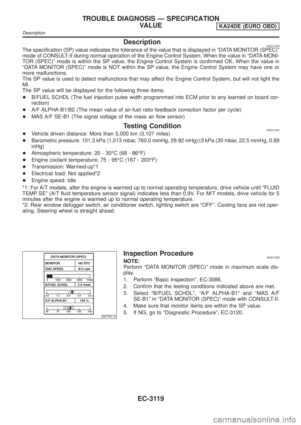
SEF601Z
Inspection ProcedureNEEC1005NOTE:
Perform ªDATA MONITOR (SPEC)º mode in maximum scale dis-
play.
1. Perform ªBasic Inspectionº, EC-3086.
2. Confirm that the testing conditions indicated above are met.
3. Select ªB/FUEL SCHDLº, ªA/F ALPHA-B1º and ªMAS A/F
SE-B1º in ªDATA MONITOR (SPEC)º mode with CONSULT-II.
4. Make sure that monitor items are within the SP value.
5. If NG, go to ªDiagnostic Procedureº, EC-3120.
TROUBLE DIAGNOSIS Ð SPECIFICATION
VALUE
KA24DE (EURO OBD)
Description
EC-3119
Page 924 of 1306

CAUTION:
+When installing camshafts, chain tensioners, oil seals,
or other sliding parts, lubricate contacting surfaces with
new engine oil.
+Apply new engine oil to threads and seat surfaces when
installing cylinder head, camshaft sprocket, crankshaft
pulley, and camshaft bracket.
+Attach tags to valve lifters so as not to mix them up.
Removal
1. Drain engine coolant. Refer to LC section, ªChanging Engine
Coolantº.
2. Remove exhaust manifold, Turbocharger. Refer to EM-3039,
ªRemoval and Installationº.
3. Remove intake manifold. Refer to EM-3035, ªRemoval and
Installationº.
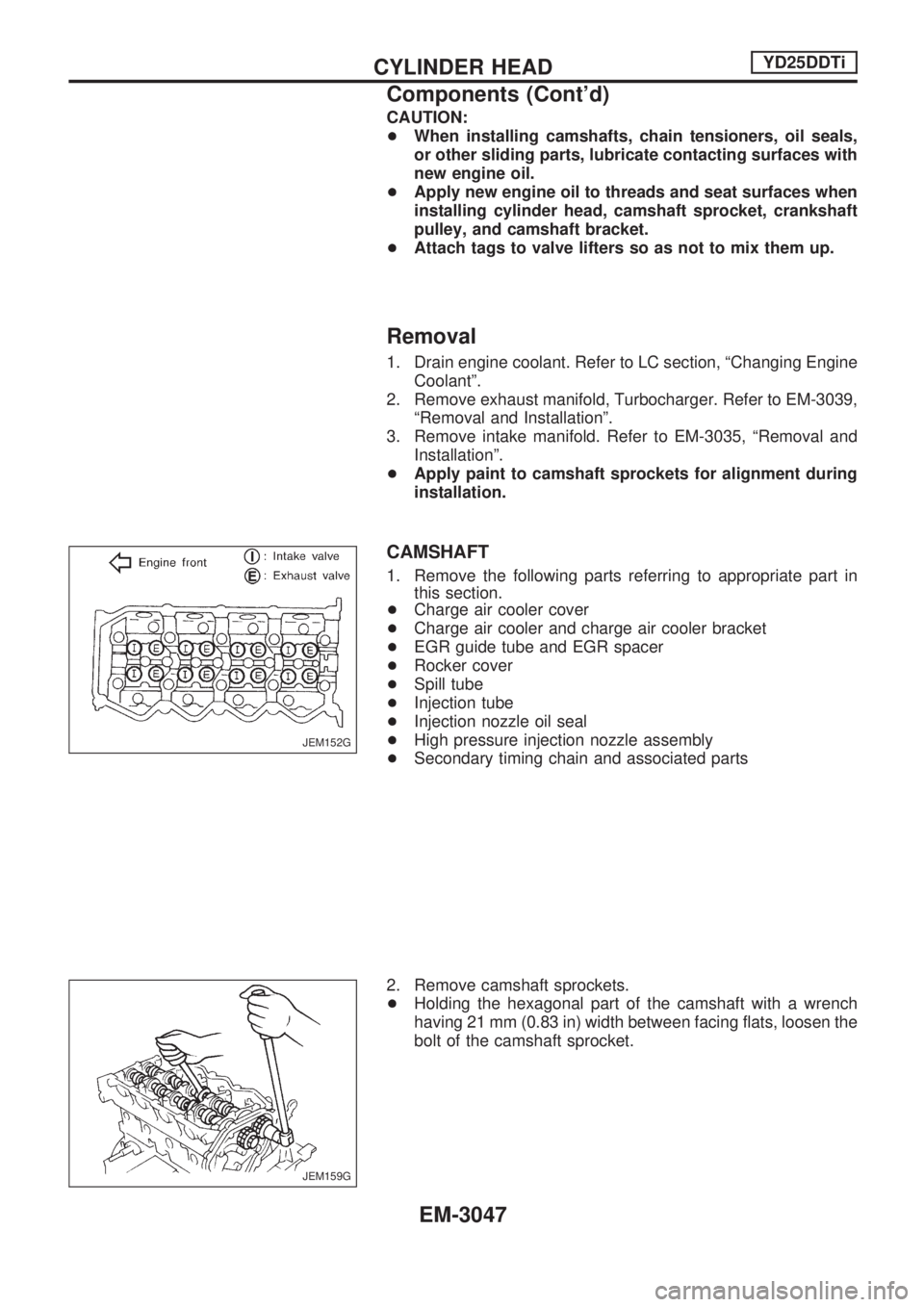
+Apply paint to camshaft sprockets for alignment during
installation.
CAMSHAFT
1. Remove the following parts referring to appropriate part in
this section.
+Charge air cooler cover
+Charge air cooler and charge air cooler bracket
+EGR guide tube and EGR spacer
+Rocker cover
+Spill tube
+Injection tube
+Injection nozzle oil seal
+High pressure injection nozzle assembly
+Secondary timing chain and associated parts
2. Remove camshaft sprockets.
+Holding the hexagonal part of the camshaft with a wrench
having 21 mm (0.83 in) width between facing flats, loosen the
bolt of the camshaft sprocket.
JEM152G
JEM159G
CYLINDER HEADYD25DDTi
Components (Cont'd)
EM-3047