2001 NISSAN PICK-UP service indicator
[x] Cancel search: service indicatorPage 26 of 1306

ENGINE CONTROL SYSTEM
SECTION
EC
CONTENTS
PRECAUTIONS AND PREPARATION............... 3008
Special Service Tool (YD25DDTi) ................... 3008
Supplemental Restraint System (SRS)²AIR
BAG²................................................................ 3008
KA24DE (EURO OBD)
Trouble Diagnosis - Index................................. 3009
Alphabetical & P No. Index for DTC................ 3009
Precautions......................................................... 3012
Supplemental Restraint System (SRS)²AIR
BAG²and²SEAT BELT PRE-TENSIONER².. 3012
Precautions for On Board Diagnostic (OBD)
System of Engine............................................. 3012
Engine Fuel & Emission Control System ........ 3013
Precautions ...................................................... 3014
Wiring Diagrams and Trouble Diagnosis ......... 3015
Preparation.......................................................... 3016
Special Service Tools ...................................... 3016
Commercial Service Tools ............................... 3016
Engine and Emission Control Overall System3018
Engine Control Component Parts Location ..... 3018
Circuit Diagram ................................................ 3020
System Diagram .............................................. 3021
Vacuum Hose Drawing .................................... 3022
System Chart ................................................... 3023
Engine and Emission Basic Control System
Description.......................................................... 3024
Multiport Fuel Injection (MFI) System.............. 3024
Distributor Ignition (DI) System........................ 3026
Air Conditioning Cut Control ............................ 3028
Fuel Cut Control (at no load & high engine
speed) .............................................................. 3028Evaporative Emission System ......................... 3029
Positive Crankcase Ventilation ........................ 3032
Basic Service Procedure................................... 3033
Fuel Pressure Release .................................... 3033
Fuel Pressure Check ....................................... 3033
Fuel Pressure Regulator Check ...................... 3034
Injector ............................................................. 3034
Fast Idle Cam (FIC) ......................................... 3035
Idle Speed/Ignition Timing/Idle Mixture Ratio
Adjustment ....................................................... 3035
On Board Diagnostic System Description...... 3049
Introduction ...................................................... 3049
Two Trip Detection Logic ................................. 3049
Emission-related Diagnostic Information ......... 3049
NVIS (Nissan Vehicle Immobilizer System -
NATS) .............................................................. 3061
Malfunction Indicator (MI) ................................ 3061
OBD System Operation Chart ......................... 3064
CONSULT-II ..................................................... 3070
Generic Scan Tool (GST) ................................ 3080
Trouble Diagnosis - Introduction..................... 3082
Introduction ...................................................... 3082
Work Flow ........................................................ 3084
Trouble Diagnosis - Basic Inspection.............. 3086
Basic Inspection ............................................... 3086
Trouble Diagnosis - General Description........ 3100
DTC Inspection Priority Chart .......................... 3100
Fail-safe Chart ................................................. 3101
Symptom Matrix Chart ..................................... 3102
CONSULT-II Reference Value in Data Monitor
Mode ................................................................ 3106
Major Sensor Reference Graph in Data
Monitor Mode ................................................... 3107
BR
Page 30 of 1306
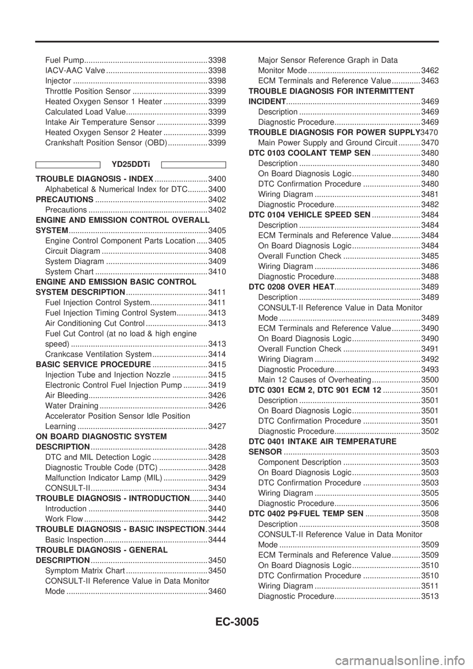
Fuel Pump........................................................ 3398
IACV-AAC Valve .............................................. 3398
Injector ............................................................. 3398
Throttle Position Sensor .................................. 3399
Heated Oxygen Sensor 1 Heater .................... 3399
Calculated Load Value..................................... 3399
Intake Air Temperature Sensor ....................... 3399
Heated Oxygen Sensor 2 Heater .................... 3399
Crankshaft Position Sensor (OBD) .................. 3399
YD25DDTi
TROUBLE DIAGNOSIS - INDEX........................ 3400
Alphabetical & Numerical Index for DTC......... 3400
PRECAUTIONS................................................... 3402
Precautions ...................................................... 3402
ENGINE AND EMISSION CONTROL OVERALL
SYSTEM............................................................... 3405
Engine Control Component Parts Location ..... 3405
Circuit Diagram ................................................ 3408
System Diagram .............................................. 3409
System Chart ................................................... 3410
ENGINE AND EMISSION BASIC CONTROL
SYSTEM DESCRIPTION..................................... 3411
Fuel Injection Control System.......................... 3411
Fuel Injection Timing Control System.............. 3413
Air Conditioning Cut Control ............................ 3413
Fuel Cut Control (at no load & high engine
speed) .............................................................. 3413
Crankcase Ventilation System ......................... 3414
BASIC SERVICE PROCEDURE......................... 3415
Injection Tube and Injection Nozzle ................ 3415
Electronic Control Fuel Injection Pump ........... 3419
Air Bleeding...................................................... 3426
Water Draining ................................................. 3426
Accelerator Position Sensor Idle Position
Learning ........................................................... 3427
ON BOARD DIAGNOSTIC SYSTEM
DESCRIPTION..................................................... 3428
DTC and MIL Detection Logic ......................... 3428
Diagnostic Trouble Code (DTC) ...................... 3428
Malfunction Indicator Lamp (MIL) .................... 3429
CONSULT-II ..................................................... 3434
TROUBLE DIAGNOSIS - INTRODUCTION........ 3440
Introduction ...................................................... 3440
Work Flow ........................................................ 3442
TROUBLE DIAGNOSIS - BASIC INSPECTION. 3444
Basic Inspection ............................................... 3444
TROUBLE DIAGNOSIS - GENERAL
DESCRIPTION..................................................... 3450
Symptom Matrix Chart ..................................... 3450
CONSULT-II Reference Value in Data Monitor
Mode ................................................................ 3460Major Sensor Reference Graph in Data
Monitor Mode ................................................... 3462
ECM Terminals and Reference Value ............. 3463
TROUBLE DIAGNOSIS FOR INTERMITTENT
INCIDENT............................................................. 3469
Description ....................................................... 3469
Diagnostic Procedure....................................... 3469
TROUBLE DIAGNOSIS FOR POWER SUPPLY3470
Main Power Supply and Ground Circuit .......... 3470
DTC 0103 COOLANT TEMP SEN...................... 3480
Description ....................................................... 3480
On Board Diagnosis Logic ............................... 3480
DTC Confirmation Procedure .......................... 3480
Wiring Diagram ................................................ 3481
Diagnostic Procedure....................................... 3482
DTC 0104 VEHICLE SPEED SEN...................... 3484
Description ....................................................... 3484
ECM Terminals and Reference Value ............. 3484
On Board Diagnosis Logic ............................... 3484
Overall Function Check ................................... 3485
Wiring Diagram ................................................ 3486
Diagnostic Procedure....................................... 3488
DTC 0208 OVER HEAT....................................... 3489
Description ....................................................... 3489
CONSULT-II Reference Value in Data Monitor
Mode ................................................................ 3489
ECM Terminals and Reference Value ............. 3490
On Board Diagnosis Logic ............................... 3490
Overall Function Check ................................... 3491
Wiring Diagram ................................................ 3492
Diagnostic Procedure....................................... 3493
Main 12 Causes of Overheating ...................... 3500
DTC 0301 ECM 2, DTC 901 ECM 12................. 3501
Description ....................................................... 3501
On Board Diagnosis Logic ............................... 3501
DTC Confirmation Procedure .......................... 3501
Diagnostic Procedure....................................... 3502
DTC 0401 INTAKE AIR TEMPERATURE
SENSOR.............................................................. 3503
Component Description ................................... 3503
On Board Diagnosis Logic ............................... 3503
DTC Confirmation Procedure .......................... 3503
Wiring Diagram ................................................ 3505
Diagnostic Procedure....................................... 3506
DTC 0402 P9zFUEL TEMP SEN......................... 3508
Description ....................................................... 3508
CONSULT-II Reference Value in Data Monitor
Mode ................................................................ 3509
ECM Terminals and Reference Value ............. 3509
On Board Diagnosis Logic ............................... 3510
DTC Confirmation Procedure .......................... 3510
Wiring Diagram ................................................ 3511
Diagnostic Procedure....................................... 3513
EC-3005
Page 37 of 1306
Supplemental Restraint System (SRS) ªAIR
BAGº and ªSEAT BELT PRE-TENSIONERº
NEEC0002The Supplemental Restraint System such as ªAIR BAGº and ªSEAT BELT PRE-TENSIONERº used along with
a seat belt, helps to reduce the risk or severity of injury to the driver and front passenger in a frontal collision.
The SRS system composition which is available to NISSAN MODEL D22 is as follows (The composition var-
ies according to the destination and optional equipment.):
Driver air bag module (located in the center of the steering wheel), front passenger air bag module (located
on the instrument panel on passenger side), seat belt pre-tensioner, a diagnosis sensor unit, warning lamp,
wiring harness and spiral cable.
Information necessary to service the system safely is included in theRS sectionof this Service Manual.
WARNING:
+To avoid rendering the SRS inoperative, which could increase the risk of personal injury or death
in the event of a collision which would result in air bag inflation, all maintenance must be performed
by an authorized NISSAN dealer.
+Improper maintenance, including incorrect removal and installation of the SRS, can lead to per-
sonal injury caused by unintentional activation of the system. For removal of Spiral Cable and Air
Bag Module, see the RS section.
+Do not use electrical test equipment on any circuit related to the SRS unless instructed to in this
Service Manual. SRS wiring harnesses can be identified by yellow harness connector.
Precautions for On Board Diagnostic (OBD)
System of Engine
NEEC0003The ECM has an on board diagnostic system. It will light up the malfunction indicator (MI) to warn the driver
of a malfunction causing emission deterioration.
CAUTION:
+Be sure to turn the ignition switch OFF and disconnect the negative battery terminal before any
repair or inspection work. The open/short circuit of related switches, sensors, solenoid valves, etc.
will cause the MI to light up.
+Be sure to connect and lock the connectors securely after work. A loose (unlocked) connector will
cause the MI to light up due to the open circuit. (Be sure the connector is free from water, grease,
dirt, bent terminals, etc.)
+Certain systems and components, especially those related to OBD, may use a new style slide-
locking type harness connector.
For description and how to disconnect, refer to EL section, ªHARNESS CONNECTORº.
+Be sure to route and secure the harnesses properly after work. The interference of the harness with
a bracket, etc. may cause the MI to light up due to the short circuit.
+Be sure to connect rubber tubes properly after work. A misconnected or disconnected rubber tube
may cause the MI to light up due to the malfunction of the fuel injection system, etc.
+Be sure to erase the unnecessary malfunction information (repairs completed) from the ECM before
returning the vehicle to the customer.
PRECAUTIONSKA24DE (EURO OBD)
Supplemental Restraint System (SRS) ªAIR BAGº and ªSEAT BELT PRE-TENSIONERº
EC-3012
Page 62 of 1306
INSPECTION PROCEDURE=NEEC0028S02
1 INSPECTION START
1. Visually check the following:
+Air cleaner clogging
+Hoses and duct for leaks
+Electrical connectors
+Gasket (intake manifold, cylinder head, exhaust system)
+Throttle valve and throttle position sensor operation
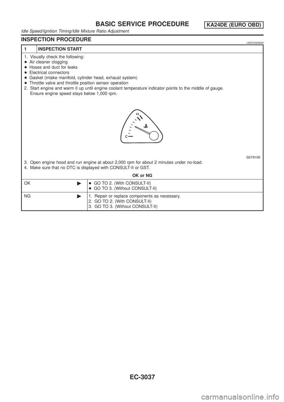
2. Start engine and warm it up until engine coolant temperature indicator points to the middle of gauge.
Ensure engine speed stays below 1,000 rpm.
SEF810K
3. Open engine hood and run engine at about 2,000 rpm for about 2 minutes under no-load.
4. Make sure that no DTC is displayed with CONSULT-II or GST.
OK or NG
OK©+GO TO 2. (With CONSULT-II)
+GO TO 3. (Without CONSULT-II)
NG©1. Repair or replace components as necessary.
2. GO TO 2. (With CONSULT-II)
3. GO TO 3. (Without CONSULT-II)
BASIC SERVICE PROCEDUREKA24DE (EURO OBD)
Idle Speed/Ignition Timing/Idle Mixture Ratio Adjustment
EC-3037
Page 72 of 1306
14 CHECK ªCOº %
Without CONSULT-II
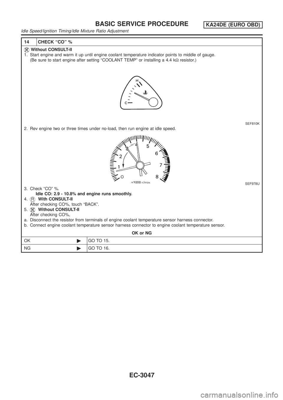
1. Start engine and warm it up until engine coolant temperature indicator points to middle of gauge.
(Be sure to start engine after setting ªCOOLANT TEMPº or installing a 4.4 kWresistor.)
SEF810K
2. Rev engine two or three times under no-load, then run engine at idle speed.
SEF978U
3. Check ªCOº %.
Idle CO: 2.9 - 10.8% and engine runs smoothly.
4.
With CONSULT-II
After checking CO%, touch ªBACKº.
5.
Without CONSULT-II
After checking CO%,
a. Disconnect the resistor from terminals of engine coolant temperature sensor harness connector.
b. Connect engine coolant temperature sensor harness connector to engine coolant temperature sensor.
OK or NG
OK©GO TO 15.
NG©GO TO 16.
BASIC SERVICE PROCEDUREKA24DE (EURO OBD)
Idle Speed/Ignition Timing/Idle Mixture Ratio Adjustment
EC-3047
Page 445 of 1306
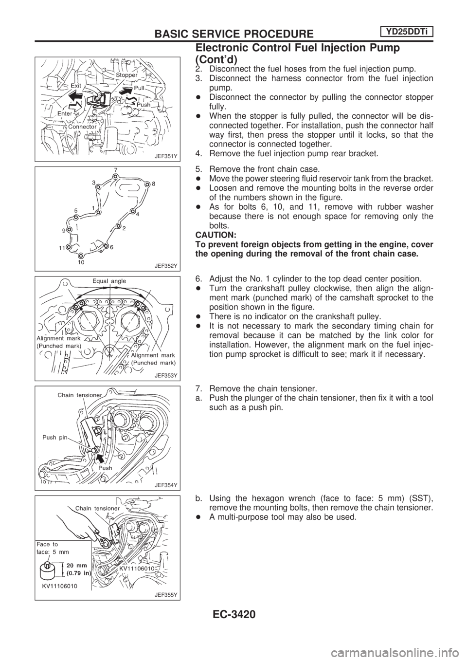
2. Disconnect the fuel hoses from the fuel injection pump.
3. Disconnect the harness connector from the fuel injection
pump.
+Disconnect the connector by pulling the connector stopper
fully.
+When the stopper is fully pulled, the connector will be dis-
connected together. For installation, push the connector half
way first, then press the stopper until it locks, so that the
connector is connected together.
4. Remove the fuel injection pump rear bracket.
5. Remove the front chain case.
+Move the power steering fluid reservoir tank from the bracket.
+Loosen and remove the mounting bolts in the reverse order
of the numbers shown in the figure.
+As for bolts 6, 10, and 11, remove with rubber washer
because there is not enough space for removing only the
bolts.
CAUTION:
To prevent foreign objects from getting in the engine, cover
the opening during the removal of the front chain case.
6. Adjust the No. 1 cylinder to the top dead center position.
+Turn the crankshaft pulley clockwise, then align the align-
ment mark (punched mark) of the camshaft sprocket to the
position shown in the figure.
+There is no indicator on the crankshaft pulley.
+It is not necessary to mark the secondary timing chain for
removal because it can be matched by the link color for
installation. However, the alignment mark on the fuel injec-
tion pump sprocket is difficult to see; mark it if necessary.
7. Remove the chain tensioner.
a. Push the plunger of the chain tensioner, then fix it with a tool
such as a push pin.
b. Using the hexagon wrench (face to face: 5 mm) (SST),
remove the mounting bolts, then remove the chain tensioner.
+A multi-purpose tool may also be used.
JEF351Y
JEF352Y
JEF353Y
JEF354Y
JEF355Y
BASIC SERVICE PROCEDUREYD25DDTi
Electronic Control Fuel Injection Pump
(Cont'd)
EC-3420
Page 824 of 1306
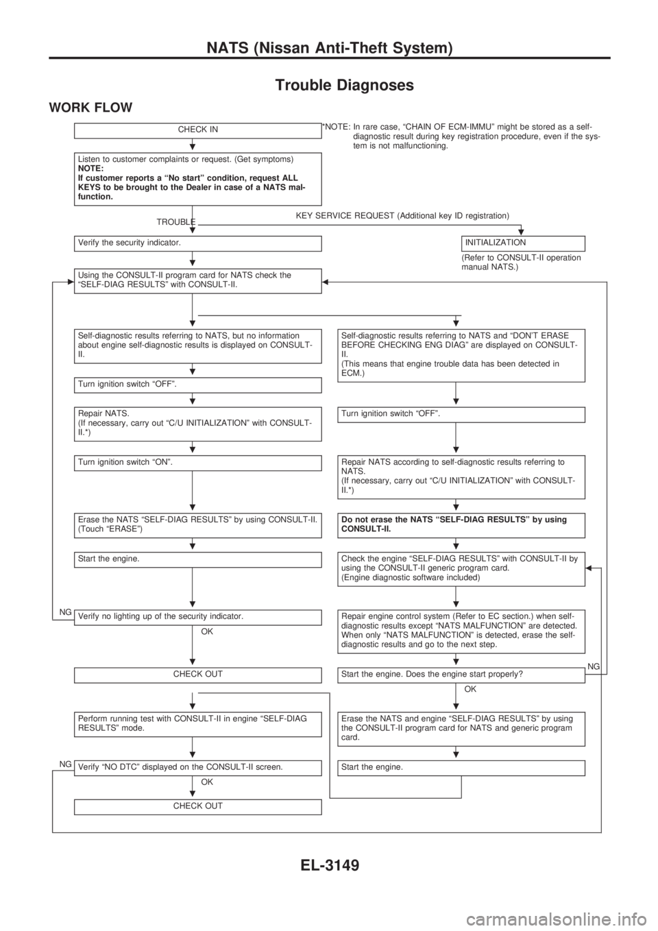
Trouble Diagnoses
WORK FLOW
CHECK IN*NOTE: In rare case, ªCHAIN OF ECM-IMMUº might be stored as a self-
diagnostic result during key registration procedure, even if the sys-
tem is not malfunctioning.
Listen to customer complaints or request. (Get symptoms)
NOTE:
If customer reports a ªNo startº condition, request ALL
KEYS to be brought to the Dealer in case of a NATS mal-
function.
TROUBLEKEY SERVICE REQUEST (Additional key ID registration).Verify the security indicator.INITIALIZATION
(Refer to CONSULT-II operation
manual NATS.)
cUsing the CONSULT-II program card for NATS check the
ªSELF-DIAG RESULTSº with CONSULT-II.b
Self-diagnostic results referring to NATS, but no information
about engine self-diagnostic results is displayed on CONSULT-
II.Self-diagnostic results referring to NATS and ªDON'T ERASE
BEFORE CHECKING ENG DIAGº are displayed on CONSULT-
II.
(This means that engine trouble data has been detected in
ECM.)
Turn ignition switch ªOFFº.
Repair NATS.
(If necessary, carry out ªC/U INITIALIZATIONº with CONSULT-
II.*)Turn ignition switch ªOFFº.
Turn ignition switch ªONº.Repair NATS according to self-diagnostic results referring to
NATS.
(If necessary, carry out ªC/U INITIALIZATIONº with CONSULT-
II.*)
Erase the NATS ªSELF-DIAG RESULTSº by using CONSULT-II.
(Touch ªERASEº)Do not erase the NATS ªSELF-DIAG RESULTSº by using
CONSULT-II.
Start the engine.Check the engine ªSELF-DIAG RESULTSº with CONSULT-II by
using the CONSULT-II generic program card.
(Engine diagnostic software included)b
NGVerify no lighting up of the security indicator.
OKRepair engine control system (Refer to EC section.) when self-
diagnostic results except ªNATS MALFUNCTIONº are detected.
When only ªNATS MALFUNCTIONº is detected, erase the self-
diagnostic results and go to the next step.
CHECK OUTStart the engine. Does the engine start properly?
OKNG
Perform running test with CONSULT-II in engine ªSELF-DIAG
RESULTSº mode.Erase the NATS and engine ªSELF-DIAG RESULTSº by using
the CONSULT-II program card for NATS and generic program
card.
NGVerify ªNO DTCº displayed on the CONSULT-II screen.
OKStart the engine.
CHECK OUT
.
.
.
..
.
..
..
..
..
..
..
..
..
.
NATS (Nissan Anti-Theft System)
EL-3149
Page 963 of 1306
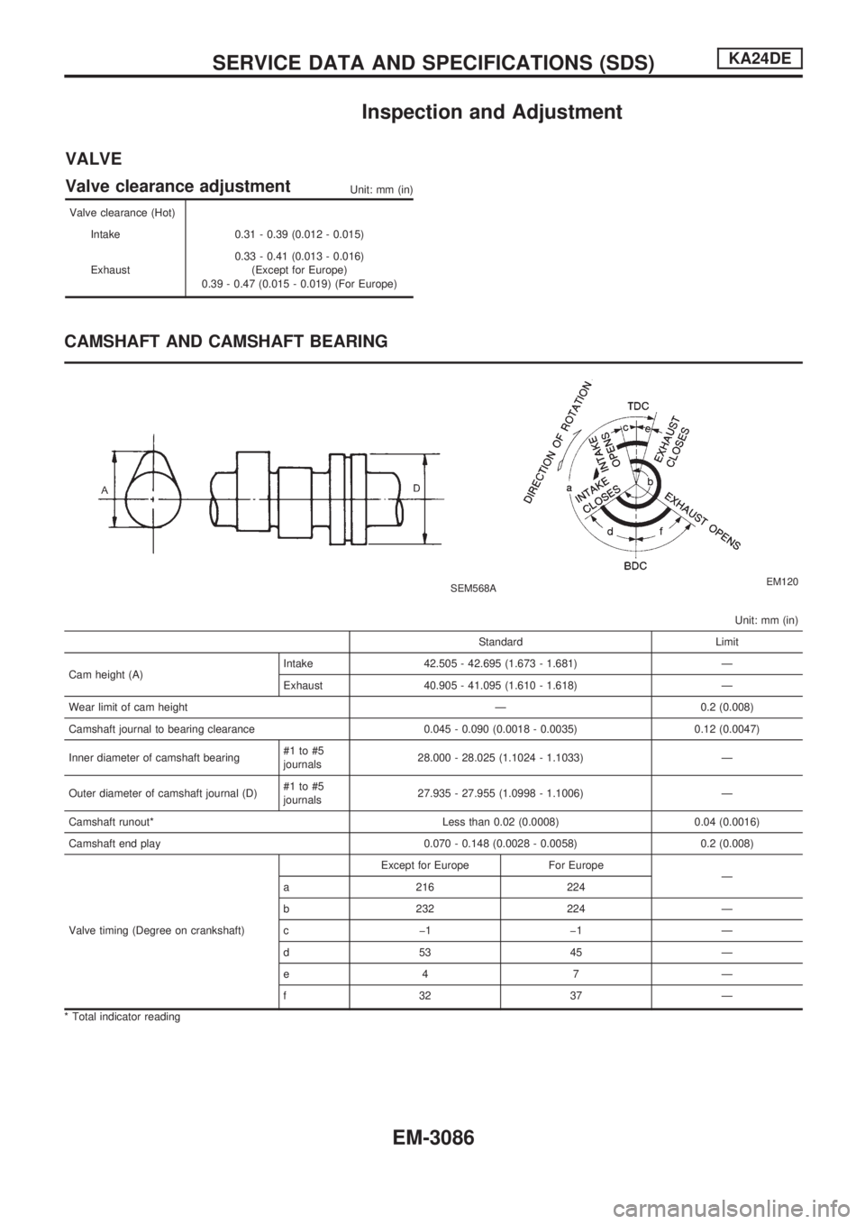
Inspection and Adjustment
VALVE
Valve clearance adjustment
Unit: mm (in)
Valve clearance (Hot)
Intake 0.31 - 0.39 (0.012 - 0.015)
Exhaust0.33 - 0.41 (0.013 - 0.016)
(Except for Europe)
0.39 - 0.47 (0.015 - 0.019) (For Europe)
CAMSHAFT AND CAMSHAFT BEARING
SEM568AEM120
Unit: mm (in)
Standard Limit
Cam height (A)Intake 42.505 - 42.695 (1.673 - 1.681) Ð
Exhaust 40.905 - 41.095 (1.610 - 1.618) Ð
Wear limit of cam height Ð 0.2 (0.008)
Camshaft journal to bearing clearance 0.045 - 0.090 (0.0018 - 0.0035) 0.12 (0.0047)
Inner diameter of camshaft bearing#1 to #5
journals28.000 - 28.025 (1.1024 - 1.1033) Ð
Outer diameter of camshaft journal (D)#1 to #5
journals27.935 - 27.955 (1.0998 - 1.1006) Ð
Camshaft runout* Less than 0.02 (0.0008) 0.04 (0.0016)
Camshaft end play 0.070 - 0.148 (0.0028 - 0.0058) 0.2 (0.008)
Valve timing (Degree on crankshaft)Except for Europe For Europe
Ð
a 216 224
b 232 224 Ð
cþ1 þ1 Ð
d53 45 Ð
e4 7 Ð
f32 37 Ð
* Total indicator reading
SERVICE DATA AND SPECIFICATIONS (SDS)KA24DE
EM-3086