2001 NISSAN PATROL maintenance
[x] Cancel search: maintenancePage 1 of 273
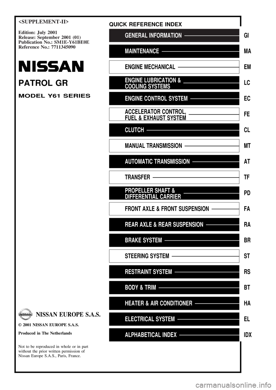
Edition: July 2001
Release: September 2001 (01)
Publication No.: SM1E-Y61BE0E
Reference No.: 7711345090GENERAL INFORMATIONGI
MAINTENANCEMA
ENGINE MECHANICALEM
ENGINE LUBRICATION &
COOLING SYSTEMSLC
ENGINE CONTROL SYSTEMEC
ACCELERATOR CONTROL,
FUEL & EXHAUST SYSTEMFE
CLUTCHCL
MANUAL TRANSMISSIONMT
AUTOMATIC TRANSMISSIONAT
TRANSFERTF
PROPELLER SHAFT &
DIFFERENTIAL CARRIERPD
FRONT AXLE & FRONT SUSPENSIONFA
REAR AXLE & REAR SUSPENSIONRA
BRAKE SYSTEMBR
STEERING SYSTEMST
RESTRAINT SYSTEMRS
BODY & TRIMBT
HEATER & AIR CONDITIONERHA
ELECTRICAL SYSTEMEL
ALPHABETICAL INDEXIDX
PATROL GR
MODEL Y61 SERIES
NISSAN EUROPE S.A.S.
2001 NISSAN EUROPE S.A.S.
Produced in The Netherlands
Not to be reproduced in whole or in part
without the prior written permission of
Nissan Europe S.A.S., Paris, France.
QUICK REFERENCE INDEX
Page 2 of 273
FOREWORD
This manual contains maintenance and repair procedures for NISSAN
PATROL GR,modelY61 series.
In order to assure your safety and the efficient functioning of the vehicle,
this manual should be read thoroughly. It is especially important that the
PRECAUTIONS in the GI section be completely understood before starting
any repair task.
All information in this manual is based on the latest product information
at the time of publication. The right is reserved to make changes in speci-
®cations and methods at any time without notice.
IMPORTANT SAFETY NOTICE
The proper performance of service is essential for both the safety of the
technician and the efficient functioning of the vehicle.
The service methods in this Service Manual are described in such a man-
ner that the service may be performed safely and accurately.
Service varies with the procedures used, the skills of the technician and the
tools and parts available. Accordingly, anyone using service procedures,
tools or parts which are not speci®cally recommended by NISSAN must
®rst completely satisfy himself that neither his safety nor the vehicle's
safety will be jeopardized by the service method selected.
NISSAN EUROPE S.A.S.
Service Engineering SectionParis, France
Page 26 of 273
Service Notice
+When removing or installing various parts, place a cloth or padding onto the vehicle body to prevent
scratches.
+Handle trim, molding, instruments, grille, etc. carefully during removing or installing. Be careful not to soil
or damage them.
+Apply sealing compound where necessary when installing parts.
+When applying sealing compound, be careful that the sealing compound does not protrude from parts.
+When replacing any metal parts (for example body outer panel, members, etc.), be sure to take rust
prevention measures.
Supplemental Restraint System (SRS) ªAIR
BAGº and ªSEAT BELT PRE-TENSIONERº
The Supplemental Restraint System such as ªAIR BAGº and ªSEAT BELT PRE-TENSIONERº used along
with a seat belt, helps to reduce the risk or severity of injury to the driver and front passenger for certain
types of collision. The SRS system composition which is available to NISSAN MODEL Y61 is as follows (The
composition varies according to the destination and optional equipment.):
+For a frontal collision
The Supplemental Restraint System consists of driver air bag module (located in the center of the
steering wheel), front passenger air bag module (located on the instrument panel on passenger side),
seat belt pre-tensioners, a diagnosis sensor unit, warning lamp, wiring harness and spiral cable.
+For a side collision
The Supplemental Restraint System consists of front side air bag module (located in the outer side of
front seat), satellite sensor, diagnosis sensor unit (one of components of air bags for a frontal collision),
wiring harness, warning lamp (one of components of air bags for a frontal collision).
Information necessary to service the system safely is included in theRS sectionof this Service Manual.
WARNING:
+To avoid rendering the SRS inoperative, which could increase the risk of personal injury or death
in the event of a collision which would result in air bag inflation, all maintenance should be per-
formed by an authorized NISSAN dealer.
+Improper maintenance, including incorrect removal and installation of the SRS, can lead to per-
sonal injury caused by unintentional activation of the system. For removal of Spiral Cable and
Air Bag Module, see the RS section.
+Do not use electrical test equipment on any circuit related to the SRS unless instructed to in this
Service Manual. SRS wiring harnesses can be identified with yellow harness connector.
PRECAUTIONS
BT-2002
Page 80 of 273
Supplemental Restraint System (SRS) ªAIR
BAGº and ªSEAT BELT PRE-TENSIONERº
The Supplemental Restraint System such as ªAIR BAGº and ªSEAT BELT PRE-TENSIONERº used along
with a seat belt, helps to reduce the risk or severity of injury to the driver and front passenger for certain
types of collision. The SRS system composition which is available to NISSAN MODEL Y61 is as follows (The
composition varies according to the destination and optional equipment.):
+For a frontal collision
The Supplemental Restraint System consists of driver air bag module (located in the center of the
steering wheel), front passenger air bag module (located on the instrument panel on passenger side),
seat belt pre-tensioners, a diagnosis sensor unit, warning lamp, wiring harness and spiral cable.
+For a side collision
The Supplemental Restraint System consists of front side air bag module (located in the outer side of
front seat), satellite sensor, diagnosis sensor unit (one of components of air bags for a frontal collision),
wiring harness, warning lamp (one of components of air bags for a frontal collision).
Information necessary to service the system safely is included in theRS sectionof this Service Manual.
WARNING:
+To avoid rendering the SRS inoperative, which could increase the risk of personal injury or death
in the event of a collision which would result in air bag inflation, all maintenance should be per-
formed by an authorized NISSAN dealer.
+Improper maintenance, including incorrect removal and installation of the SRS, can lead to per-
sonal injury caused by intentional activation of the system. For removal of Spiral Cable and Air
Bag Module, see the RS section.
+Do not use electrical test equipment on any circuit related to the SRS unless instructed to in this
Service Manual. SRS wiring harnesses can be identified by yellow harness connector.
PRECAUTIONS AND PREPARATION
EL-2003
Page 221 of 273
Supplemental Restraint System (SRS) ªAIR
BAGº and ªSEAT BELT PRE-TENSIONERº
The Supplemental Restraint System such as ªAIR BAGº and ªSEAT BELT PRE-TENSIONERº used along
with a seat belt, helps to reduce the risk or severity of injury to the driver and front passenger for certain
types of collision. The SRS system composition which is available to NISSAN MODEL Y61 is as follows (The
composition varies according to the destination and optional equipment.):
+For a frontal collision
The Supplemental Restraint System consists of driver air bag module (located in the center of the
steering wheel), front passenger air bag module (located on the instrument panel on passenger side),
seat belt pre-tensioners, a diagnosis sensor unit, warning lamp, wiring harness and spiral cable.
+For a side collision
The Supplemental Restraint System consists of front side air bag module (located in the outer side of
front seat), satellite sensor, diagnosis sensor unit (one of components of air bags for a frontal collision),
wiring harness, warning lamp (one of components of air bags for a frontal collision).
Information necessary to service the system safely is included in theRS sectionof this Service Manual.
WARNING:
+To avoid rendering the SRS inoperative, which could increase the risk of personal injury or death
in the event of a collision which would result in air bag inflation, all maintenance should be per-
formed by an authorized NISSAN dealer.
+Improper maintenance, including incorrect removal and installation of the SRS, can lead to per-
sonal injury caused by unintentional activation of the system. For removal of Spiral Cable and
Air Bag Module, see the RS section.
+Do not use electrical test equipment on any circuit related to the SRS unless instructed to in this
Service Manual. Spiral cable and wiring harnesses covered with yellow insulation tape either just
before the harness connectors or for the complete harness are related to the SRS.
PRECAUTIONS AND PREPARATION
HA-2002
Page 234 of 273
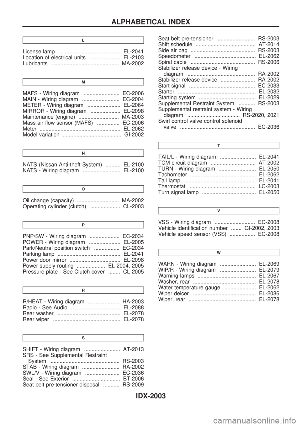
L
License lamp ......................................... EL-2041
Location of electrical units ..................... EL-2103
Lubricants ............................................. MA-2002
M
MAFS - Wiring diagram ........................ EC-2006
MAIN - Wiring diagram ......................... EC-2004
METER - Wiring diagram ...................... EL-2064
MIRROR - Wiring diagram .................... EL-2098
Maintenance (engine) ........................... MA-2003
Mass air flow sensor (MAFS) ............... EC-2006
Meter ...................................................... EL-2062
Model variation ....................................... GI-2002
N
NATS (Nissan Anti-theft System) .......... EL-2100
NATS - Wiring diagram ......................... EL-2100
O
Oil change (capacity) ............................ MA-2002
Operating cylinder (clutch) .................... CL-2003
P
PNP/SW - Wiring diagram .................... EC-2034
POWER - Wiring diagram ..................... EL-2005
Park/Neutral position switch ................. EC-2034
Parking lamp .......................................... EL-2041
Power door mirror .................................. EL-2098
Power supply routing ................... EL-2004, 2005
Pressure plate - See Clutch cover ........ CL-2005
R
R/HEAT - Wiring diagram ..................... HA-2003
Radio - See Audio ................................. EL-2088
Rear washer .......................................... EL-2078
Rear wiper ............................................. EL-2078
S
SHIFT - Wiring diagram ........................ AT-2013
SRS - See Supplemental Restraint
System .............................................. RS-2003
STAB - Wiring diagram ......................... RA-2002
SWL/V - Wiring diagram ....................... EC-2036
Seal - See Exterior ................................ BT-2006
Seat belt pre-tensioner disposal ........... RS-2009Seat belt pre-tensioner ......................... RS-2003
Shift schedule ........................................ AT-2014
Side air bag ........................................... RS-2003
Speedometer ......................................... EL-2062
Spiral cable ........................................... RS-2006
Stabilizer release device - Wiring
diagram ............................................. RA-2002
Stabilizer release device ....................... RA-2002
Start signal ............................................ EC-2033
Starter .................................................... EL-2032
Starting system ...................................... EL-2029
Supplemental Restraint System ........... RS-2003
Supplemental restraint system - Wiring
diagram ................................... RS-2020, 2021
Swirl control valve control solenoid
valve .................................................. EC-2036
T
TAIL/L - Wiring diagram ........................ EL-2041
TCM circuit diagram .............................. AT-2002
TURN - Wiring diagram ......................... EL-2050
Tachometer ............................................ EL-2062
Tail lamp ................................................ EL-2041
Thermostat ............................................ LC-2003
Turn signal lamp .................................... EL-2050
V
VSS - Wiring diagram ........................... EC-2008
Vehicle identification number ....... GI-2002, 2003
Vehicle speed sensor (VSS) ................. EC-2008
W
WARN - Wiring diagram ........................ EL-2069
WIP/R - Wiring diagram ........................ EL-2079
Warning lamps ....................................... EL-2067
Washer, rear .......................................... EL-2078
Water temperature gauge ..................... EL-2062
Wiper deicer .......................................... EL-2086
Wiper, rear ............................................. EL-2078
ALPHABETICAL INDEX
IDX-2003
Page 240 of 273
MAINTENANCE
SECTION
MA
CONTENTS
RECOMMENDED FLUIDS AND LUBRICANTS. 2002
Fluids and Lubricants....................................... 2002ENGINE MAINTENANCE.................................... 2003
Changing Engine Coolant ................................ 2003
MA
Page 242 of 273
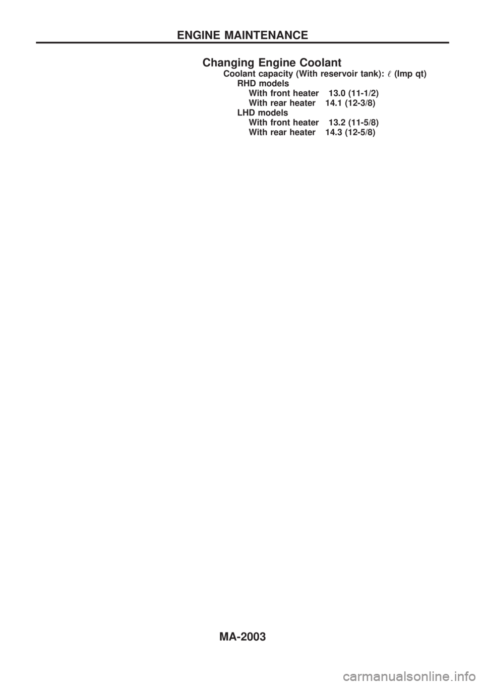
Changing Engine Coolant
Coolant capacity (With reservoir tank):!(Imp qt)
RHD models
With front heater 13.0 (11-1/2)
With rear heater 14.1 (12-3/8)
LHD models
With front heater 13.2 (11-5/8)
With rear heater 14.3 (12-5/8)
ENGINE MAINTENANCE
MA-2003