2001 NISSAN ALMERA TINO wiring diagram
[x] Cancel search: wiring diagramPage 2702 of 3051

S
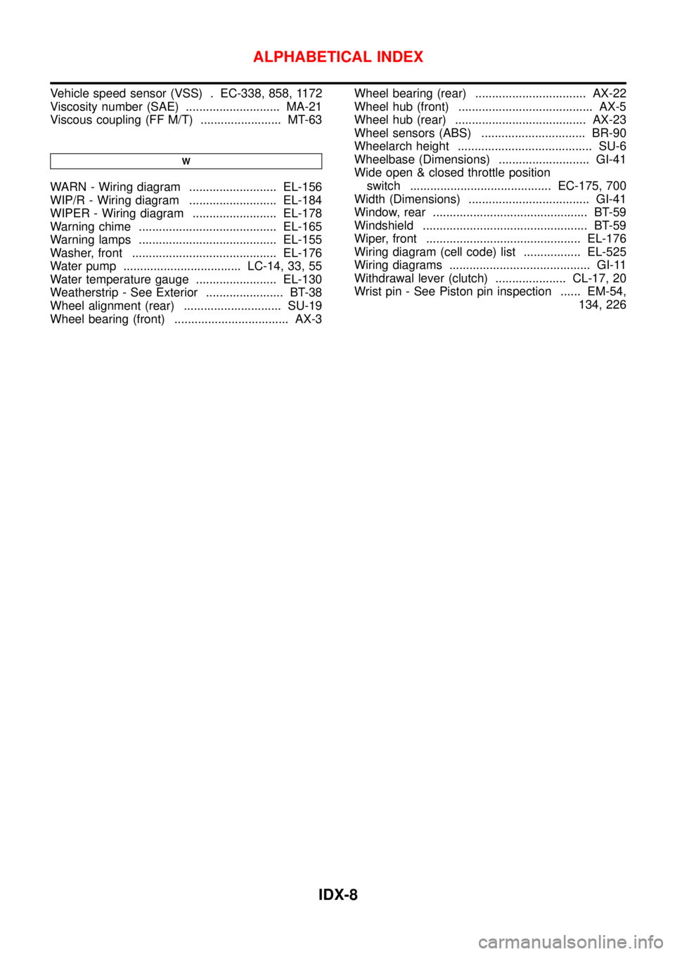
S/LOCK - Wiring diagram ................ EL-260, 286
S/SIG - Wiring diagram ................. EC-512, 1028
SAE J1930 terminology list ........................ GI-48
SHIFT - Wiring diagram ........................... AT-196
SROOF - Wiring diagram ........................ EL-238
SRS - See Supplemental Restraint
System ................................................... RS-16
START - Wiring diagram ........................... SC-14
STOP/L - Wiring diagram .......................... EL-91
SWL/V - Wiring diagram ................. EC-366, 481
Seal - See Exterior .................................... BT-38
Seat belt pre-tensioner disposal ............... RS-30
Seat belt pre-tensioner ............................... RS-3
Seat belt, front ............................................ RS-5
Seat belt, rear ............................................. RS-7
Seat, front .................................................. BT-46
Seat, rear ................................................... BT-49
Self-diagnostic results ............ EC-73, 598, 1098
Shift control components (M/T) .......... MT-26, 64
Shift fork (M/T) .................................... MT-26, 64
Shift lever .................................................. MT-23
Shift lock system ...................................... AT-195
Shock absorber (front) .............................. SU-11
Shock absorber (rear) ............................... SU-23
Side air bag ............................................... RS-28
Side trim .................................................... BT-28
Speedometer ........................................... EL-130
Spiral cable ............................................... RS-24
Spring (Wheelarch) height .......................... SU-6
Stabilizer bar (front) .................................. SU-12
Stall test (A/T) ............................................ AT-51
Standardized relay ....................................... EL-7
Start signal .......................... EC-511, 1027, 1293
Starter ....................................................... SC-17
Starting system ......................................... SC-13
Steering linkage ......................................... ST-15
Steering switch .......................................... EL-67
Steering wheel and column ....................... ST-10
Steering wheel play ..................................... ST-6
Steering wheel turning force ....................... ST-8
Stop lamp .................................................. EL-91
Striking rod (M/T) ................................ MT-26, 64
Strut (front) ................................................ SU-10
Strut (rear) ................................................. SU-22
Sub-gear (M/T) .......................................... MT-25
Sunroof, electric ....................................... EL-238
Sunroof ...................................................... BT-51
Super lock ................................................ EL-281
Supplemental Restraint System ............... RS-16
Swirl control valve control solenoid
valve .................................. EC-366, 481, 1285
Symbols and abbreviations .......................... GI-9
Symptom matrix chart ........... EC-124, 648, 1116
Synchronizer (M/T) ............................. MT-25, 63
System readiness test (SRT) code ... EC-62, 586
T
TCM circuit diagram ................................... AT-13
TCM inspection table ................................. AT-58
TP/SW - Wiring diagram ................. EC-354, 874
TPS - Wiring diagram ..................... EC-178, 703
TURN - Wiring diagram ........................... EL-102
Tachometer .............................................. EL-130
Tail lamp .................................................... EL-87
Thermostat .................................... LC-15, 35, 57
Three way catalyst precautions ................... GI-6
Three way catalyst .......................... EC-327, 848
Throttle position sensor (TPS) ........ EC-175, 700
Throttle position sensor adjustment .. EC-99, 623
Throttle position switch ................... AT-111, 145,
EC-352, 872
Throwout bearing - See Clutch release
bearing ............................................. CL-17, 20
Tie-rod ball joints ....................................... ST-18
Tie-rod ........................................................ ST-15
Tightening torque of standard bolts ........... GI-47
Timing belt .......................................... EM-22, 96
Timing chain ........................................... EM-175
Tire size ...................................................... GI-41
Torque converter installation .................... AT-207
Tow truck towing ........................................ GI-45
Transmission case (M/T) .................... MT-24, 62
Tread-FR&RR (Dimensions) ...................... GI-41
Trim ............................................................ BT-28
Trouble diagnoses ...................................... GI-31
Trunk lid finisher ........................................ BT-31
Trunk lid opener - See Trunk lid ................ BT-10
Trunk lid trim .............................................. BT-31
Trunk lid ..................................................... BT-10
Trunk room trim ......................................... BT-31
Turn signal lamp ...................................... EL-101
Two trip detection logic ..................... EC-59, 583
Two-pole lift ................................................ GI-44
U
Under body ................................................ BT-68
V
VSS - Wiring diagram ........... EC-340, 860, 1172
Vacuum hose (brake system) ................... BR-18
Vacuum hose drawing (Engine control) ... EC-33,
567, 1077
Vacuum pump ........................................... BR-20
Valve clearance ................................ EM-42, 214
Valve guide ............................... EM-38, 116, 205
Valve lifter ................................................. EM-41
Valve seat ................................. EM-40, 117, 207
Valve spring .............................. EM-41, 119, 209
ALPHABETICAL INDEX
IDX-7
Page 2703 of 3051

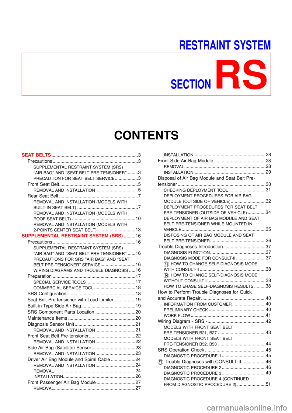
Vehicle speed sensor (VSS) . EC-338, 858, 1172
Viscosity number (SAE) ............................ MA-21
Viscous coupling (FF M/T) ........................ MT-63
W
WARN - Wiring diagram .......................... EL-156
WIP/R - Wiring diagram .......................... EL-184
WIPER - Wiring diagram ......................... EL-178
Warning chime ......................................... EL-165
Warning lamps ......................................... EL-155
Washer, front ........................................... EL-176
Water pump ................................... LC-14, 33, 55
Water temperature gauge ........................ EL-130
Weatherstrip - See Exterior ....................... BT-38
Wheel alignment (rear) ............................. SU-19
Wheel bearing (front) .................................. AX-3Wheel bearing (rear) ................................. AX-22
Wheel hub (front) ........................................ AX-5
Wheel hub (rear) ....................................... AX-23
Wheel sensors (ABS) ............................... BR-90
Wheelarch height ........................................ SU-6
Wheelbase (Dimensions) ........................... GI-41
Wide open & closed throttle position
switch .......................................... EC-175, 700
Width (Dimensions) .................................... GI-41
Window, rear .............................................. BT-59
Windshield ................................................. BT-59
Wiper, front .............................................. EL-176
Wiring diagram (cell code) list ................. EL-525
Wiring diagrams .......................................... GI-11
Withdrawal lever (clutch) ..................... CL-17, 20
Wrist pin - See Piston pin inspection ...... EM-54,
134, 226
ALPHABETICAL INDEX
IDX-8
Page 2892 of 3051

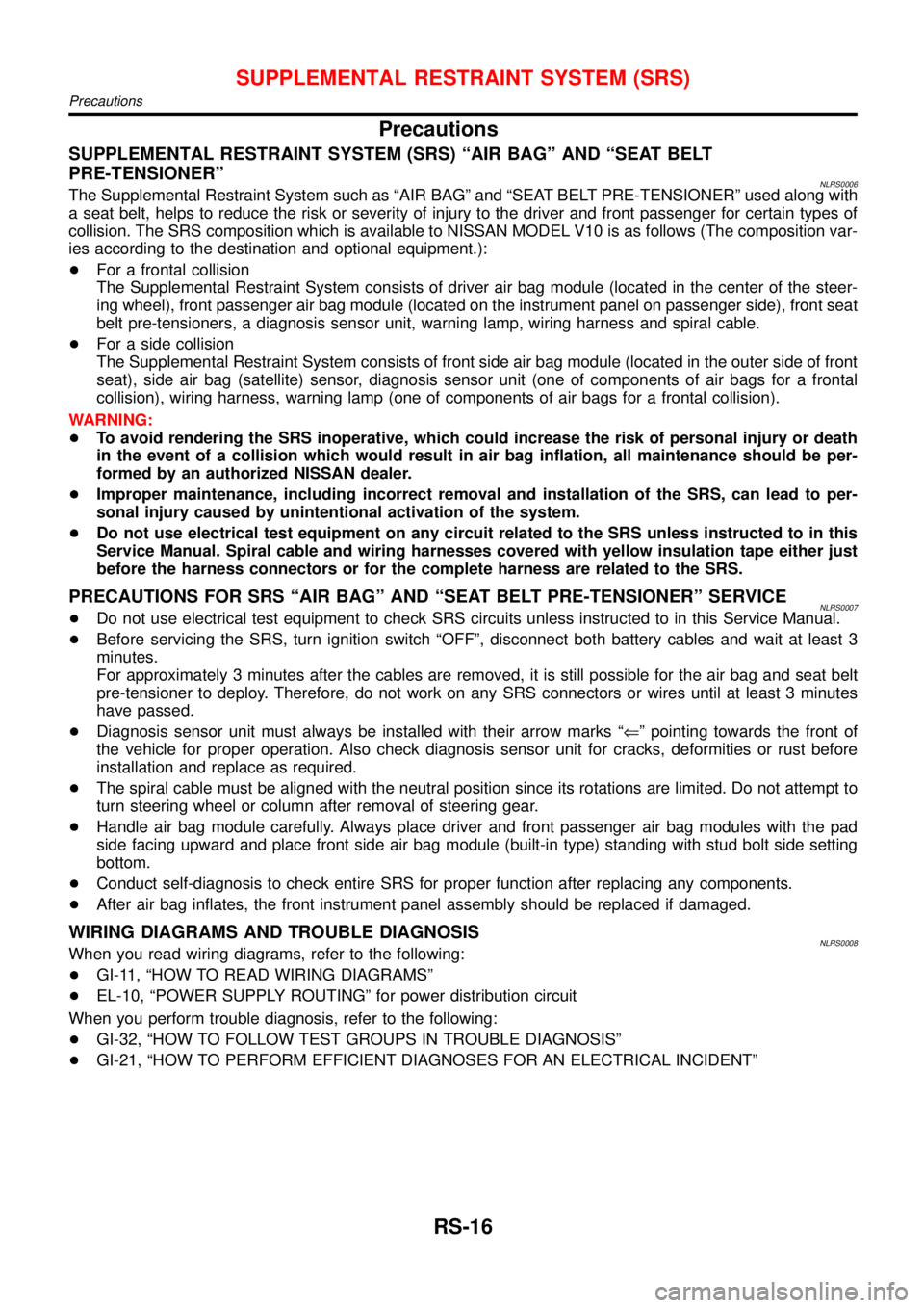
RESTRAINT SYSTEM
SECTION
RS
CONTENTS
SEAT BELTS...................................................................3
Precautions ..................................................................3
SUPPLEMENTAL RESTRAINT SYSTEM (SRS)
″AIR BAG″AND″SEAT BELT PRE-TENSIONER″
........3
PRECAUTION FOR SEAT BELT SERVICE..................3
Front Seat Belt.............................................................5
REMOVAL AND INSTALLATION.................................5
Rear Seat Belt .............................................................7
REMOVAL AND INSTALLATION (MODELS WITH
BUILT-IN SEAT BELT)
...............................................7
REMOVAL AND INSTALLATION (MODELS WITH
ROOF SEAT BELT)
.................................................10
REMOVAL AND INSTALLATION (MODELS WITH
2-POINTS CENTER SEAT BELT)
..............................13
SUPPLEMENTAL RESTRAINT SYSTEM (SRS).........16
Precautions ................................................................16
SUPPLEMENTAL RESTRAINT SYSTEM (SRS)
″AIR BAG″AND″SEAT BELT PRE-TENSIONER″
......16
PRECAUTIONS FOR SRS″AIR BAG″AND″SEAT
BELT PRE-TENSIONER″SERVICE
...........................16
WIRING DIAGRAMS AND TROUBLE DIAGNOSIS.....16
Preparation ................................................................17
SPECIAL SERVICE TOOLS......................................17
COMMERCIAL SERVICE TOOL................................18
SRS Configuration .....................................................18
Seat Belt Pre-tensioner with Load Limiter.................19
Built-in Type Side Air Bag..........................................19
SRS Component Parts Location ...............................20
Maintenance Items ....................................................20
Diagnosis Sensor Unit ...............................................21
REMOVAL AND INSTALLATION...............................21
Front Seat Belt Pre-tensioner ....................................22
REMOVAL AND INSTALLATION...............................22
Side Air Bag (Satellite) Sensor ..................................23
REMOVAL AND INSTALLATION...............................23
Driver Air Bag Module and Spiral Cable ...................24
REMOVAL AND INSTALLATION...............................24
REMOVAL...............................................................24
INSTALLATION........................................................26
Front Passenger Air Bag Module ..............................27
REMOVAL...............................................................27
INSTALLATION........................................................28
Front Side Air Bag Module ........................................28
REMOVAL...............................................................28
INSTALLATION........................................................29
Disposal of Air Bag Module and Seat Belt Pre-
tensioner ....................................................................30
CHECKING DEPLOYMENT TOOL.............................31
DEPLOYMENT PROCEDURES FOR AIR BAG
MODULE (OUTSIDE OF VEHICLE)
...........................32
DEPLOYMENT PROCEDURES FOR SEAT BELT
PRE-TENSIONER (OUTSIDE OF VEHICLE)
..............34
DEPLOYMENT OF AIR BAG MODULE AND SEAT
BELT PRE-TENSIONER WHILE MOUNTED IN
VEHICLE
.................................................................35
DISPOSING OF AIR BAG MODULE AND SEAT
BELT PRE-TENSIONER
...........................................36
Trouble Diagnoses Introduction.................................37
DIAGNOSIS FUNCTION...........................................37
DIAGNOSIS MODE FOR CONSULT-II.......................37
HOW TO CHANGE SELF-DIAGNOSIS MODE
WITH CONSULT-II
...................................................38
HOW TO CHANGE SELF-DIAGNOSIS MODE
WITHOUT CONSULT-II
............................................38
HOW TO ERASE SELF-DIAGNOSIS RESULTS.........38
How to Perform Trouble Diagnoses for Quick
and Accurate Repair ..................................................40
INFORMATION FROM CUSTOMER..........................40
PRELIMINARY CHECK............................................40
WORK FLOW..........................................................41
Wiring Diagram - SRS -.............................................42
MODELS WITH FRONT SEAT BELT
PRE-TENSIONER B21, B27
.....................................43
MODELS WITH FRONT SEAT BELT
PRE-TENSIONER B52, B53
.....................................44
SRS Operation Check ...............................................45
DIAGNOSTIC PROCEDURE 1..................................45
Trouble Diagnoses with CONSULT-II...................46
DIAGNOSTIC PROCEDURE 2..................................46
DIAGNOSTIC PROCEDURE 3..................................49
DIAGNOSTIC PROCEDURE 4 (CONTINUED
FROM DIAGNOSTIC PROCEDURE 2)
......................51
Page 2907 of 3051

Precautions
SUPPLEMENTAL RESTRAINT SYSTEM (SRS)“AIR BAG”AND“SEAT BELT
PRE-TENSIONER”
NLRS0006The Supplemental Restraint System such as“AIR BAG”and“SEAT BELT PRE-TENSIONER”used along with
a seat belt, helps to reduce the risk or severity of injury to the driver and front passenger for certain types of
collision. The SRS composition which is available to NISSAN MODEL V10 is as follows (The composition var-
ies according to the destination and optional equipment.):
+For a frontal collision
The Supplemental Restraint System consists of driver air bag module (located in the center of the steer-
ing wheel), front passenger air bag module (located on the instrument panel on passenger side), front seat
belt pre-tensioners, a diagnosis sensor unit, warning lamp, wiring harness and spiral cable.
+For a side collision
The Supplemental Restraint System consists of front side air bag module (located in the outer side of front
seat), side air bag (satellite) sensor, diagnosis sensor unit (one of components of air bags for a frontal
collision), wiring harness, warning lamp (one of components of air bags for a frontal collision).
WARNING:
+To avoid rendering the SRS inoperative, which could increase the risk of personal injury or death
in the event of a collision which would result in air bag inflation, all maintenance should be per-
formed by an authorized NISSAN dealer.
+Improper maintenance, including incorrect removal and installation of the SRS, can lead to per-
sonal injury caused by unintentional activation of the system.
+Do not use electrical test equipment on any circuit related to the SRS unless instructed to in this
Service Manual. Spiral cable and wiring harnesses covered with yellow insulation tape either just
before the harness connectors or for the complete harness are related to the SRS.
PRECAUTIONS FOR SRS“AIR BAG”AND“SEAT BELT PRE-TENSIONER”SERVICENLRS0007+Do not use electrical test equipment to check SRS circuits unless instructed to in this Service Manual.
+Before servicing the SRS, turn ignition switch“OFF”, disconnect both battery cables and wait at least 3
minutes.
For approximately 3 minutes after the cables are removed, it is still possible for the air bag and seat belt
pre-tensioner to deploy. Therefore, do not work on any SRS connectors or wires until at least 3 minutes
have passed.
+Diagnosis sensor unit must always be installed with their arrow marks“⇐”pointing towards the front of
the vehicle for proper operation. Also check diagnosis sensor unit for cracks, deformities or rust before
installation and replace as required.
+The spiral cable must be aligned with the neutral position since its rotations are limited. Do not attempt to
turn steering wheel or column after removal of steering gear.
+Handle air bag module carefully. Always place driver and front passenger air bag modules with the pad
side facing upward and place front side air bag module (built-in type) standing with stud bolt side setting
bottom.
+Conduct self-diagnosis to check entire SRS for proper function after replacing any components.
+After air bag inflates, the front instrument panel assembly should be replaced if damaged.
WIRING DIAGRAMS AND TROUBLE DIAGNOSISNLRS0008When you read wiring diagrams, refer to the following:
+GI-11,“HOW TO READ WIRING DIAGRAMS”
+EL-10,“POWER SUPPLY ROUTING”for power distribution circuit
When you perform trouble diagnosis, refer to the following:
+GI-32,“HOW TO FOLLOW TEST GROUPS IN TROUBLE DIAGNOSIS”
+GI-21,“HOW TO PERFORM EFFICIENT DIAGNOSES FOR AN ELECTRICAL INCIDENT”
SUPPLEMENTAL RESTRAINT SYSTEM (SRS)
Precautions
RS-16
Page 2933 of 3051

Wiring Diagram—SRS—NLRS0061
YRS044
SUPPLEMENTAL RESTRAINT SYSTEM (SRS)
Wiring Diagram—SRS—
RS-42
Page 2934 of 3051

MODELS WITH FRONT SEAT BELT PRE-TENSIONER B21, B27NLRS0061S01
YRS045
SUPPLEMENTAL RESTRAINT SYSTEM (SRS)
Wiring Diagram—SRS—(Cont’d)
RS-43
Page 2935 of 3051

MODELS WITH FRONT SEAT BELT PRE-TENSIONER B52, B53NLRS0061S02
YRS052
SUPPLEMENTAL RESTRAINT SYSTEM (SRS)
Wiring Diagram—SRS—(Cont’d)
RS-44
Page 2962 of 3051

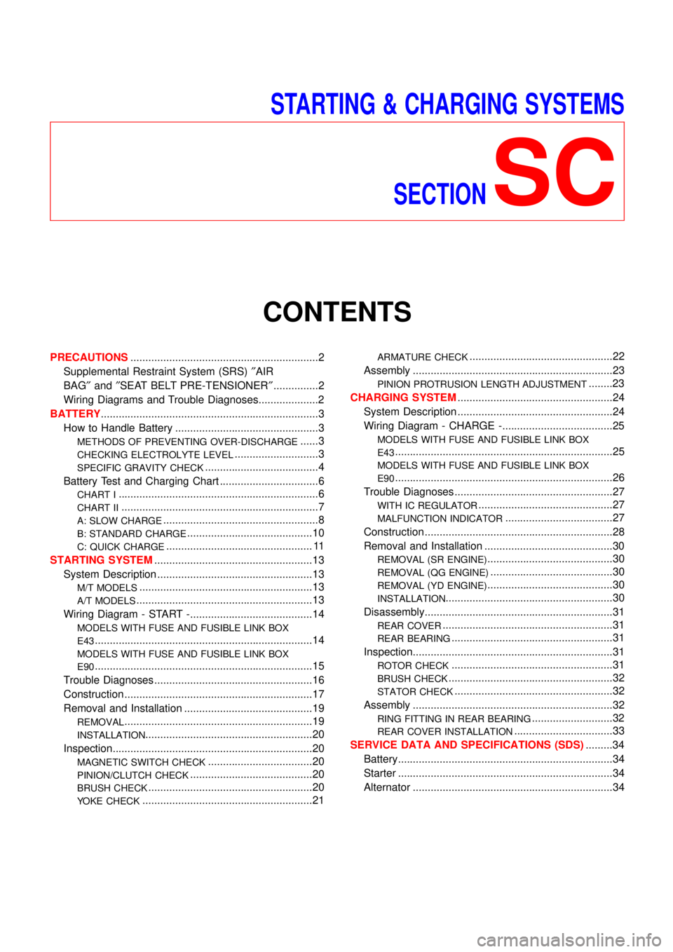
STARTING & CHARGING SYSTEMS
SECTION
SC
CONTENTS
PRECAUTIONS...............................................................2
Supplemental Restraint System (SRS)″AIR
BAG″and″SEAT BELT PRE-TENSIONER″...............2
Wiring Diagrams and Trouble Diagnoses....................2
BATTERY.........................................................................3
How to Handle Battery ................................................3
METHODS OF PREVENTING OVER-DISCHARGE......3
CHECKING ELECTROLYTE LEVEL............................3
SPECIFIC GRAVITY CHECK......................................4
Battery Test and Charging Chart .................................6
CHART I...................................................................6
CHART II..................................................................7
A: SLOW CHARGE....................................................8
B: STANDARD CHARGE..........................................10
C: QUICK CHARGE................................................. 11
STARTING SYSTEM.....................................................13
System Description ....................................................13
M/T MODELS..........................................................13
A/T MODELS...........................................................13
Wiring Diagram - START -.........................................14
MODELS WITH FUSE AND FUSIBLE LINK BOX
E43
.........................................................................14
MODELS WITH FUSE AND FUSIBLE LINK BOX
E90
.........................................................................15
Trouble Diagnoses.....................................................16
Construction ...............................................................17
Removal and Installation ...........................................19
REMOVAL...............................................................19
INSTALLATION........................................................20
Inspection...................................................................20
MAGNETIC SWITCH CHECK...................................20
PINION/CLUTCH CHECK.........................................20
BRUSH CHECK.......................................................20
YOKE CHECK.........................................................21
ARMATURE CHECK................................................22
Assembly ...................................................................23
PINION PROTRUSION LENGTH ADJUSTMENT........23
CHARGING SYSTEM....................................................24
System Description ....................................................24
Wiring Diagram - CHARGE -.....................................25
MODELS WITH FUSE AND FUSIBLE LINK BOX
E43
.........................................................................25
MODELS WITH FUSE AND FUSIBLE LINK BOX
E90
.........................................................................26
Trouble Diagnoses.....................................................27
WITH IC REGULATOR.............................................27
MALFUNCTION INDICATOR....................................27
Construction ...............................................................28
Removal and Installation ...........................................30
REMOVAL (SR ENGINE)..........................................30
REMOVAL (QG ENGINE).........................................30
REMOVAL (YD ENGINE)..........................................30
INSTALLATION........................................................30
Disassembly...............................................................31
REAR COVER.........................................................31
REAR BEARING......................................................31
Inspection...................................................................31
ROTOR CHECK......................................................31
BRUSH CHECK.......................................................32
STATOR CHECK.....................................................32
Assembly ...................................................................32
RING FITTING IN REAR BEARING...........................32
REAR COVER INSTALLATION.................................33
SERVICE DATA AND SPECIFICATIONS (SDS).........34
Battery........................................................................34
Starter ........................................................................34
Alternator ...................................................................34