2001 NISSAN ALMERA TINO fuel
[x] Cancel search: fuelPage 2529 of 3051
SFE642A
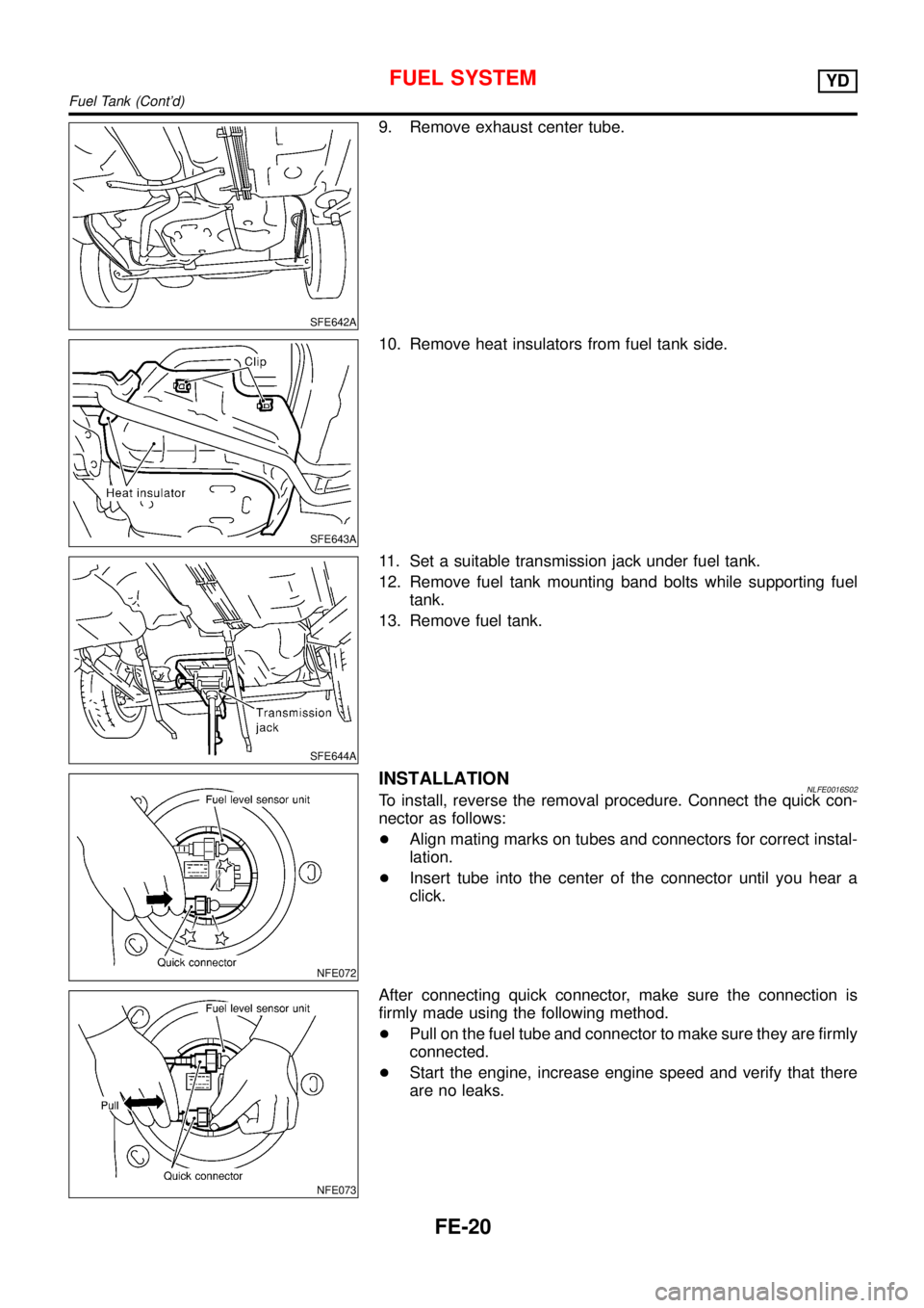
9. Remove exhaust center tube.
SFE643A
10. Remove heat insulators from fuel tank side.
SFE644A
11. Set a suitable transmission jack under fuel tank.
12. Remove fuel tank mounting band bolts while supporting fuel
tank.
13. Remove fuel tank.
NFE072
INSTALLATIONNLFE0016S02To install, reverse the removal procedure. Connect the quick con-
nector as follows:
+Align mating marks on tubes and connectors for correct instal-
lation.
+Insert tube into the center of the connector until you hear a
click.
NFE073
After connecting quick connector, make sure the connection is
firmly made using the following method.
+Pull on the fuel tube and connector to make sure they are firmly
connected.
+Start the engine, increase engine speed and verify that there
are no leaks.
FUEL SYSTEMYD
Fuel Tank (Cont’d)
FE-20
Page 2530 of 3051
Fuel Level Sensor UnitNLFE0032
NFE074
JFE613A
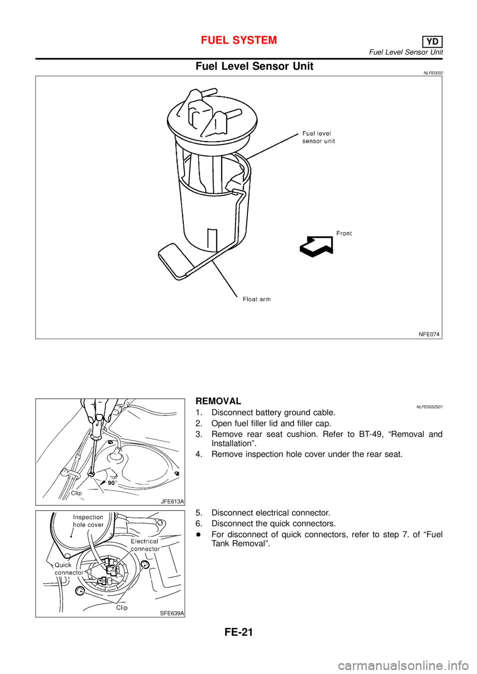
REMOVALNLFE0032S011. Disconnect battery ground cable.
2. Open fuel filler lid and filler cap.
3. Remove rear seat cushion. Refer to BT-49,“Removal and
Installation”.
4. Remove inspection hole cover under the rear seat.
SFE639A
5. Disconnect electrical connector.
6. Disconnect the quick connectors.
+For disconnect of quick connectors, refer to step 7. of“Fuel
Tank Removal”.
FUEL SYSTEMYD
Fuel Level Sensor Unit
FE-21
Page 2531 of 3051
SFE376A
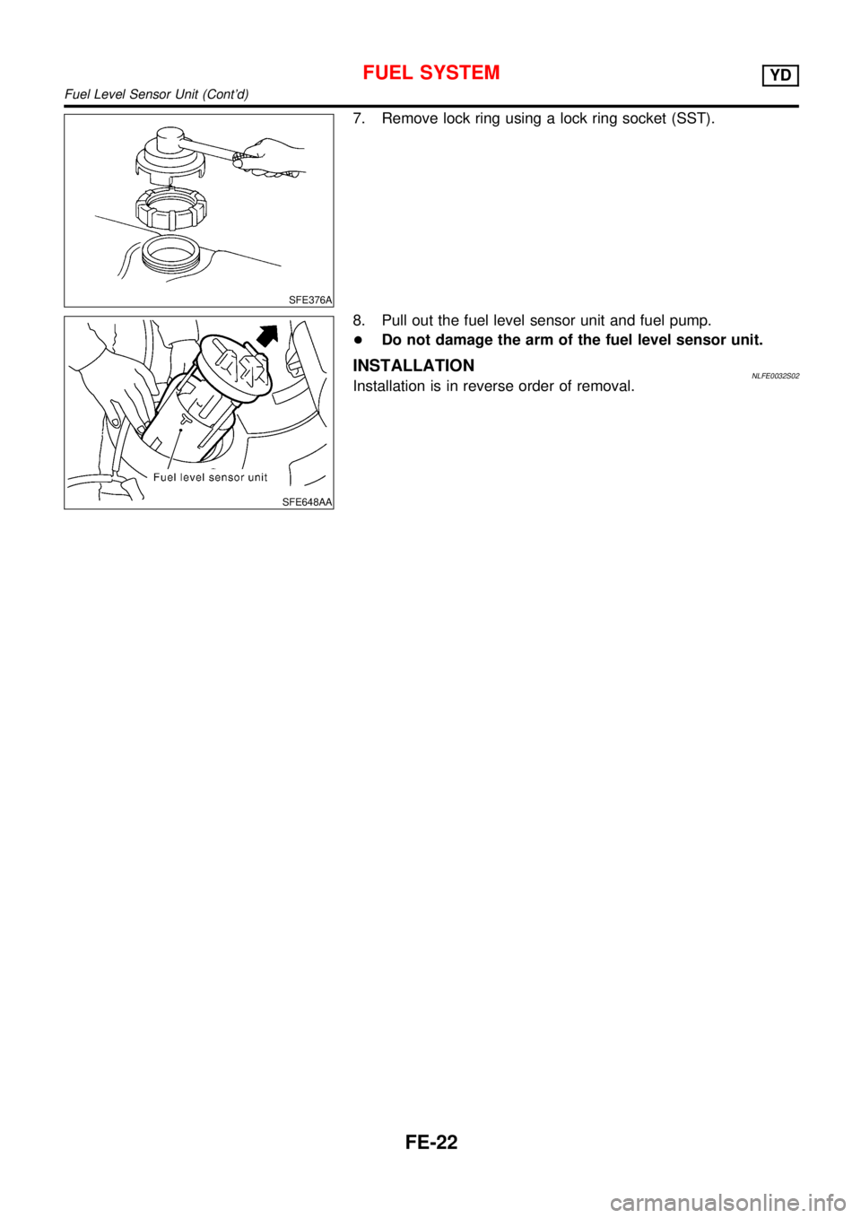
7. Remove lock ring using a lock ring socket (SST).
SFE648AA
8. Pull out the fuel level sensor unit and fuel pump.
+Do not damage the arm of the fuel level sensor unit.
INSTALLATIONNLFE0032S02Installation is in reverse order of removal.
FUEL SYSTEMYD
Fuel Level Sensor Unit (Cont’d)
FE-22
Page 2540 of 3051
GENERAL INFORMATION
SECTION
GI
CONTENTS
PRECAUTIONS...............................................................3
Precautions ..................................................................3
PRECAUTIONS FOR SUPPLEMENTAL
RESTRAINT SYSTEM (SRS)″AIR BAG″AND
″SEAT BELT PRE-TENSIONER″
.................................3
PRECAUTIONS FOR NATS (NISSAN ANTI-THEFT
SYSTEM)
..................................................................3
GENERAL PRECAUTIONS.........................................4
PRECAUTIONS FOR MULTIPORT FUEL
INJECTION SYSTEM OR ENGINE CONTROL
SYSTEM
...................................................................6
PRECAUTIONS FOR THREE WAY CATALYST...........6
PRECAUTIONS FOR HOSES.....................................6
PRECAUTIONS FOR ENGINE OILS...........................7
PRECAUTIONS FOR FUEL........................................8
PRECAUTIONS FOR AIR CONDITIONING..................8
HOW TO USE THIS MANUAL........................................9
HOW TO READ WIRING DIAGRAMS.......................... 11
Sample/Wiring Diagram - EXAMPL - ........................ 11
OPTIONAL SPLICE..................................................12
Description .................................................................13
CONNECTOR SYMBOLS.........................................15
HARNESS INDICATION...........................................16
COMPONENT INDICATION......................................16
SWITCH POSITIONS...............................................16
DETECTABLE LINES AND NON-DETECTABLE
LINES
.....................................................................17
MULTIPLE SWITCH.................................................18
REFERENCE AREA.................................................19
HOW TO PERFORM EFFICIENT DIAGNOSES
FOR AN ELECTRICAL INCIDENT...............................21
Work Flow ..................................................................21
Incident Simulation Tests ...........................................22
INTRODUCTION......................................................22
VEHICLE VIBRATION..............................................22
HEAT SENSITIVE....................................................23
FREEZING..............................................................23
WATER INTRUSION................................................24
ELECTRICAL LOAD.................................................24
COLD OR HOT START UP.......................................24
Circuit Inspection .......................................................24
INTRODUCTION......................................................24
TESTING FOR″OPENS″IN THE CIRCUIT................25
TESTING FOR″SHORTS″IN THE CIRCUIT..............26
GROUND INSPECTION...........................................27
VOLTAGE DROP TESTS..........................................27
CONTROL UNIT CIRCUIT TEST...............................29
HOW TO FOLLOW TROUBLE DIAGNOSES...............31
How to Follow Test Groups in Trouble Diagnoses ....32
Key to Symbols Signifying Measurements or
Procedures.................................................................33
CONSULT-II CHECKING SYSTEM...............................35
Function and System Application ..............................35
Nickel Metal Hydride Battery Replacement...............35
Checking Equipment..................................................36
CONSULT-II Data Link Connector (DLC) Circuit ......36
INSPECTION PROCEDURE.....................................36
IDENTIFICATION INFORMATION................................37
Model Variation ..........................................................37
PREFIX AND SUFFIX DESIGNATIONS.....................37
Identification Number .................................................38
VEHICLE IDENTIFICATION NUMBER
ARRANGEMENT
.....................................................38
IDENTIFICATION PLATE..........................................39
ENGINE SERIAL NUMBER.......................................39
H.CVT NUMBER......................................................40
MANUAL TRANSAXLE NUMBER..............................40
Dimensions ................................................................41
Wheels and Tires .......................................................41
LIFTING POINTS AND TOW TRUCK TOWING...........42
Preparation ................................................................42
SPECIAL SERVICE TOOLS......................................42
Board-on Lift ..............................................................42
Garage Jack and Safety Stand .................................43
2-pole Lift ...................................................................44
Tow Truck Towing ......................................................45
TOWING A H.CVT MODEL WITH FOUR WHEELS
ON GROUND
..........................................................45
TOWING A H.CVT MODEL WITH REAR WHEELS
RAISED (WITH FRONT WHEELS ON GROUND)
.......45
TOWING POINT.......................................................46
Page 2544 of 3051
SEF289H
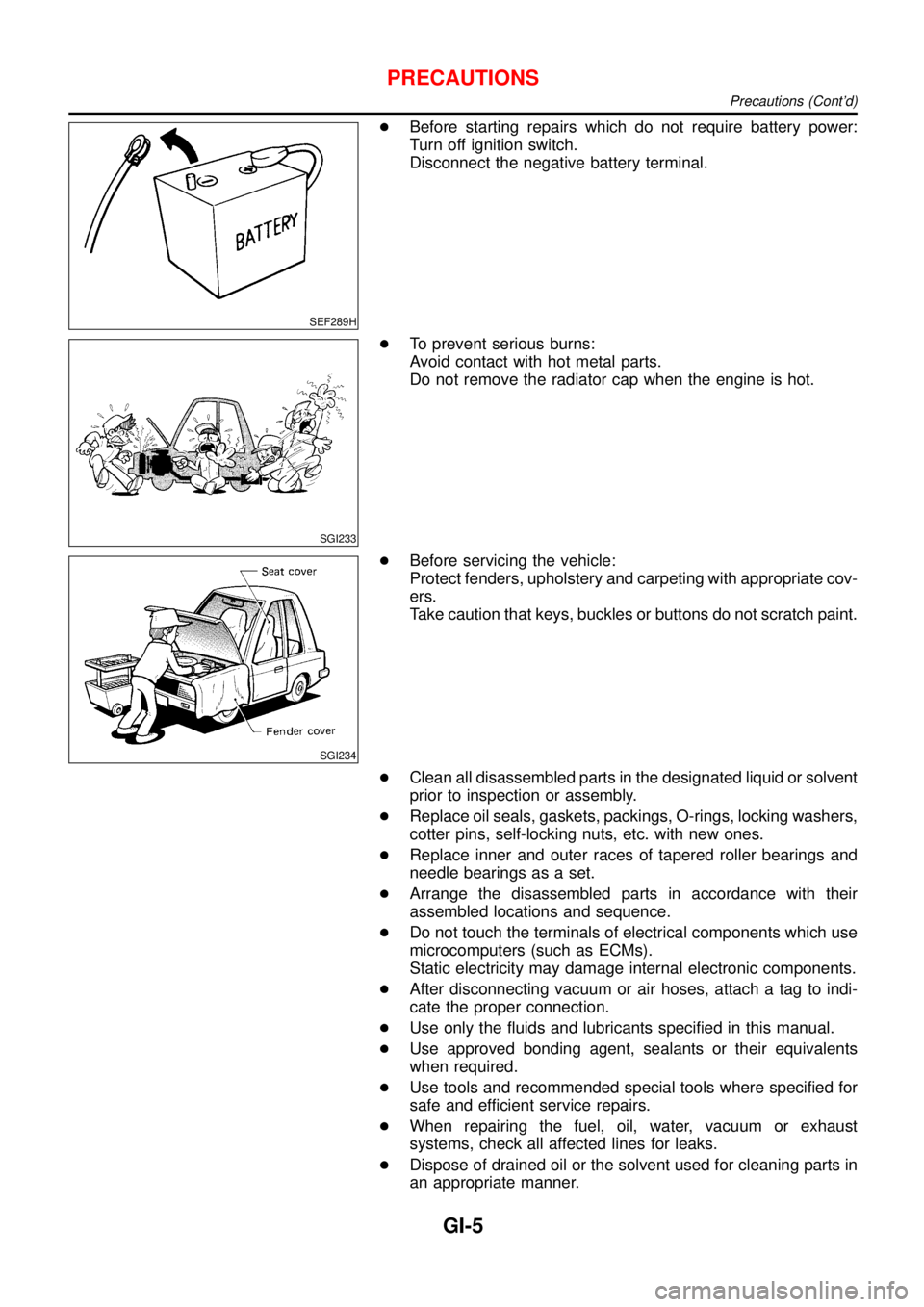
+Before starting repairs which do not require battery power:
Turn off ignition switch.
Disconnect the negative battery terminal.
SGI233
+To prevent serious burns:
Avoid contact with hot metal parts.
Do not remove the radiator cap when the engine is hot.
SGI234
+Before servicing the vehicle:
Protect fenders, upholstery and carpeting with appropriate cov-
ers.
Take caution that keys, buckles or buttons do not scratch paint.
+Clean all disassembled parts in the designated liquid or solvent
prior to inspection or assembly.
+Replace oil seals, gaskets, packings, O-rings, locking washers,
cotter pins, self-locking nuts, etc. with new ones.
+Replace inner and outer races of tapered roller bearings and
needle bearings as a set.
+Arrange the disassembled parts in accordance with their
assembled locations and sequence.
+Do not touch the terminals of electrical components which use
microcomputers (such as ECMs).
Static electricity may damage internal electronic components.
+After disconnecting vacuum or air hoses, attach a tag to indi-
cate the proper connection.
+Use only the fluids and lubricants specified in this manual.
+Use approved bonding agent, sealants or their equivalents
when required.
+Use tools and recommended special tools where specified for
safe and efficient service repairs.
+When repairing the fuel, oil, water, vacuum or exhaust
systems, check all affected lines for leaks.
+Dispose of drained oil or the solvent used for cleaning parts in
an appropriate manner.
PRECAUTIONS
Precautions (Cont’d)
GI-5
Page 2545 of 3051
Do not attempt to top up the fuel tank after the fuel pump nozzle
shuts off automatically. Continued refueling may cause fuel
overflow, resulting in fuel spray and possibly a fire.
WARNING:
To prevent ECM from storing the diagnostic trouble codes, do
not carelessly disconnect the harness connectors which are
related to the engine control system and TCM (Transmission
Control Module) system. The connectors should be discon-
nected only when working according to the WORK FLOW of
TROUBLE DIAGNOSES in EC and AT sections.
SGI787
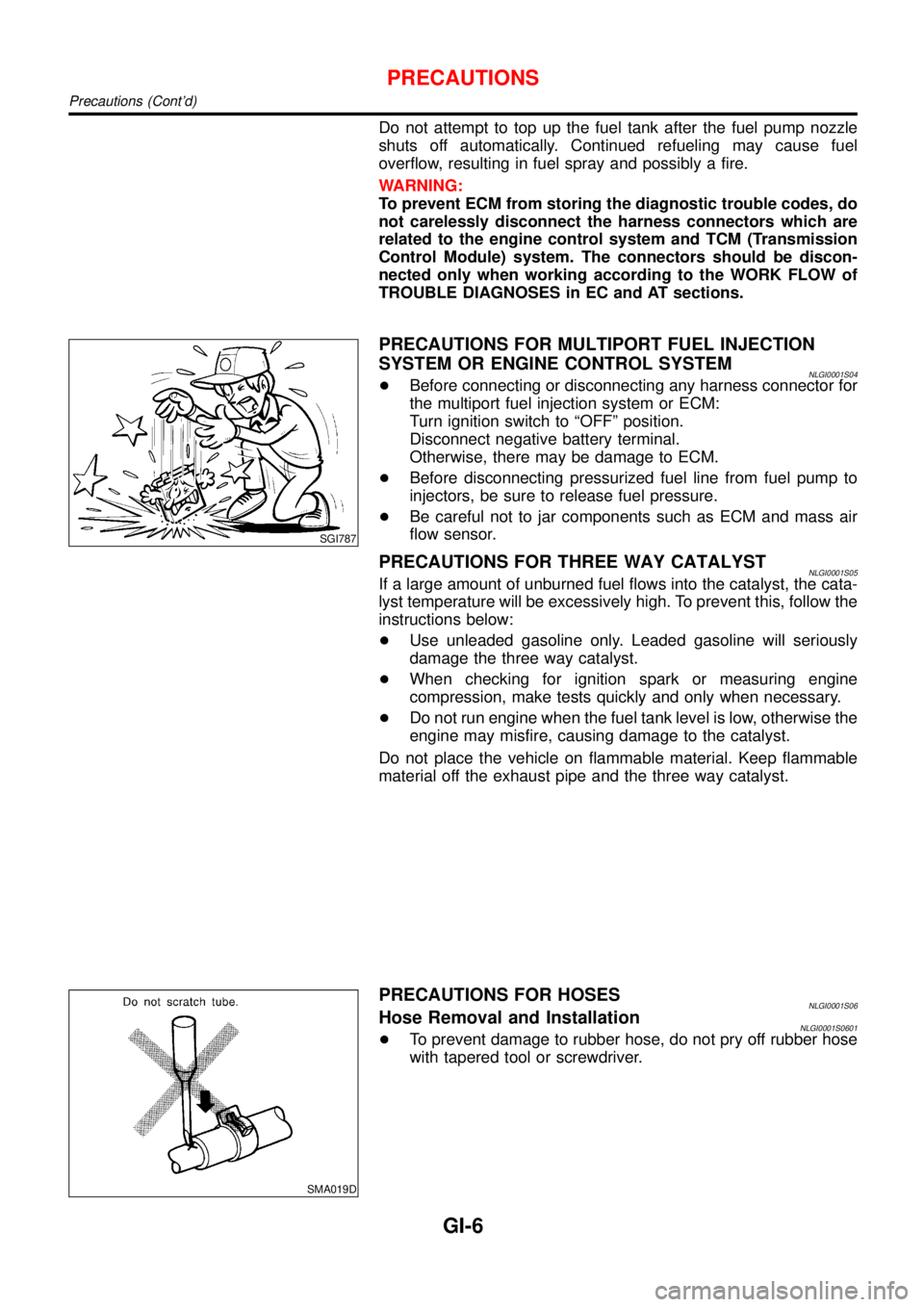
PRECAUTIONS FOR MULTIPORT FUEL INJECTION
SYSTEM OR ENGINE CONTROL SYSTEM
NLGI0001S04+Before connecting or disconnecting any harness connector for
the multiport fuel injection system or ECM:
Turn ignition switch to“OFF”position.
Disconnect negative battery terminal.
Otherwise, there may be damage to ECM.
+Before disconnecting pressurized fuel line from fuel pump to
injectors, be sure to release fuel pressure.
+Be careful not to jar components such as ECM and mass air
flow sensor.
PRECAUTIONS FOR THREE WAY CATALYSTNLGI0001S05If a large amount of unburned fuel flows into the catalyst, the cata-
lyst temperature will be excessively high. To prevent this, follow the
instructions below:
+Use unleaded gasoline only. Leaded gasoline will seriously
damage the three way catalyst.
+When checking for ignition spark or measuring engine
compression, make tests quickly and only when necessary.
+Do not run engine when the fuel tank level is low, otherwise the
engine may misfire, causing damage to the catalyst.
Do not place the vehicle on flammable material. Keep flammable
material off the exhaust pipe and the three way catalyst.
SMA019D
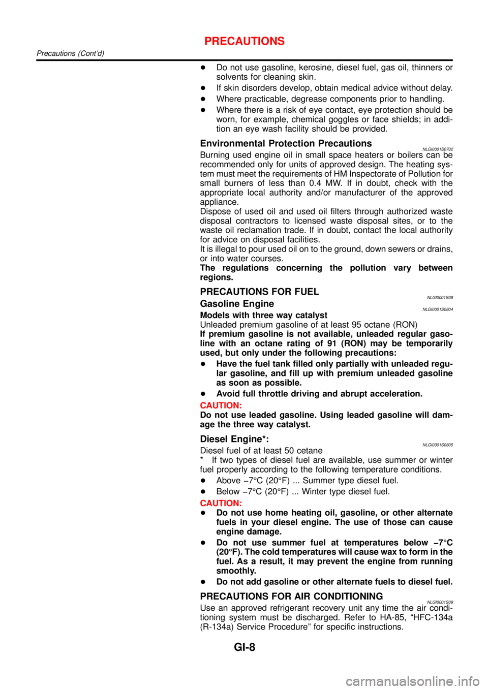
PRECAUTIONS FOR HOSESNLGI0001S06Hose Removal and InstallationNLGI0001S0601+To prevent damage to rubber hose, do not pry off rubber hose
with tapered tool or screwdriver.
PRECAUTIONS
Precautions (Cont’d)
GI-6
Page 2547 of 3051
+Do not use gasoline, kerosine, diesel fuel, gas oil, thinners or
solvents for cleaning skin.
+If skin disorders develop, obtain medical advice without delay.
+Where practicable, degrease components prior to handling.
+Where there is a risk of eye contact, eye protection should be
worn, for example, chemical goggles or face shields; in addi-
tion an eye wash facility should be provided.
Environmental Protection PrecautionsNLGI0001S0702Burning used engine oil in small space heaters or boilers can be
recommended only for units of approved design. The heating sys-
tem must meet the requirements of HM Inspectorate of Pollution for
small burners of less than 0.4 MW. If in doubt, check with the
appropriate local authority and/or manufacturer of the approved
appliance.
Dispose of used oil and used oil filters through authorized waste
disposal contractors to licensed waste disposal sites, or to the
waste oil reclamation trade. If in doubt, contact the local authority
for advice on disposal facilities.
It is illegal to pour used oil on to the ground, down sewers or drains,
or into water courses.
The regulations concerning the pollution vary between
regions.
PRECAUTIONS FOR FUELNLGI0001S08Gasoline EngineNLGI0001S0804Models with three way catalyst
Unleaded premium gasoline of at least 95 octane (RON)
If premium gasoline is not available, unleaded regular gaso-
line with an octane rating of 91 (RON) may be temporarily
used, but only under the following precautions:
+Have the fuel tank filled only partially with unleaded regu-
lar gasoline, and fill up with premium unleaded gasoline
as soon as possible.
+Avoid full throttle driving and abrupt acceleration.
CAUTION:
Do not use leaded gasoline. Using leaded gasoline will dam-
age the three way catalyst.
Diesel Engine*:NLGI0001S0805Diesel fuel of at least 50 cetane
* If two types of diesel fuel are available, use summer or winter
fuel properly according to the following temperature conditions.
+Above �7°C (20°F) ... Summer type diesel fuel.
+Below �7°C (20°F) ... Winter type diesel fuel.
CAUTION:
+Do not use home heating oil, gasoline, or other alternate
fuels in your diesel engine. The use of those can cause
engine damage.
+Do not use summer fuel at temperatures below �7°C
(20°F). The cold temperatures will cause wax to form in the
fuel. As a result, it may prevent the engine from running
smoothly.
+Do not add gasoline or other alternate fuels to diesel fuel.
PRECAUTIONS FOR AIR CONDITIONINGNLGI0001S09Use an approved refrigerant recovery unit any time the air condi-
tioning system must be discharged. Refer to HA-85, “HFC-134a
(R-134a) Service Procedure” for specific instructions.
PRECAUTIONS
Precautions (Cont’d)
GI-8
Page 2583 of 3051
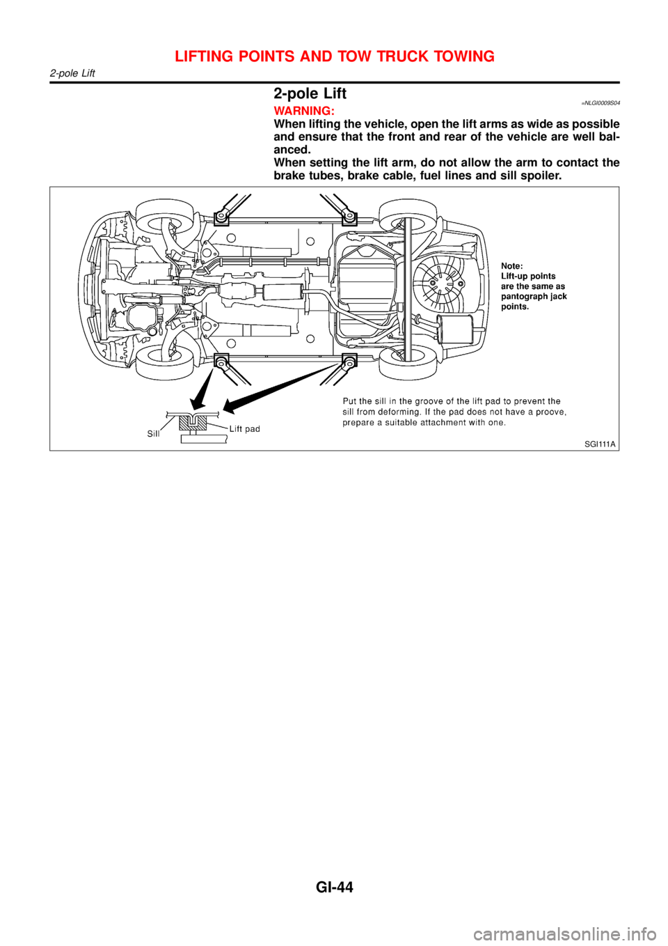
2-pole Lift=NLGI0009S04WARNING:
When lifting the vehicle, open the lift arms as wide as possible
and ensure that the front and rear of the vehicle are well bal-
anced.
When setting the lift arm, do not allow the arm to contact the
brake tubes, brake cable, fuel lines and sill spoiler.
SGI111A
LIFTING POINTS AND TOW TRUCK TOWING
2-pole Lift
GI-44