Page 464 of 3051
+When the engine coolant temperature becomes excessively high.
+When operating power steering during low engine speed or low vehicle speed.
+When engine speed is excessively low.
+When the refrigerant pressure is excessively high or low.
Fuel Cut Control (at no load & high engine
speed)
DESCRIPTIONNLEC0017Input/Output Signal ChartNLEC0017S01
Sensor Input Signal to ECMECM func-
tionActuator
Vehicle speed sensor Vehicle speed
Fuel cut
controlInjectors PNP switch Neutral position
Throttle position sensor Throttle position
Engine coolant temperature sensor Engine coolant temperature
Crankshaft position sensor (POS) Engine speed
Camshaft position sensor (PHASE) Engine speed and cylinder number
If the engine speed is above 3,950 rpm with no load, (for example, in Neutral and engine speed over 4,000
rpm) fuel will be cut off after some time. The exact time when the fuel is cut off varies based on engine speed.
Fuel cut will operate until the engine speed reaches 1,150 rpm, then fuel cut is cancelled.
NOTE:
This function is different from deceleration control listed under ªMultiport Fuel Injection (MFI) Systemº,
EC-35.
Evaporative Emission System
DESCRIPTIONNLEC0018
SEF916WA
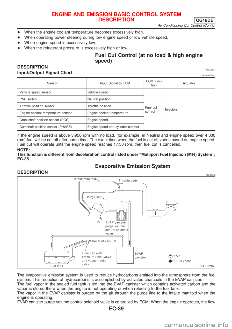
The evaporative emission system is used to reduce hydrocarbons emitted into the atmosphere from the fuel
system. This reduction of hydrocarbons is accomplished by activated charcoals in the EVAP canister.
The fuel vapor in the sealed fuel tank is led into the EVAP canister which contains activated carbon and the
vapor is stored there when the engine is not operating or when refueling to the fuel tank.
The vapor in the EVAP canister is purged by the air through the purge line to the intake manifold when the
engine is operating.
EVAP canister purge volume control solenoid valve is controlled by ECM. When the engine operates, the flow
ENGINE AND EMISSION BASIC CONTROL SYSTEM
DESCRIPTION
QG18DE
Air Conditioning Cut Control (Cont'd)
EC-39
Page 472 of 3051
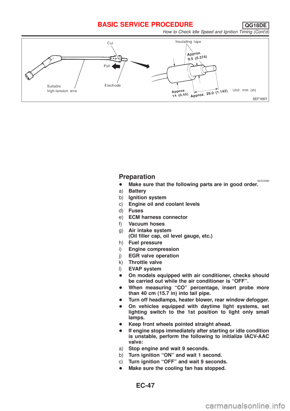
SEF166Y
PreparationNLEC0592+Make sure that the following parts are in good order.
a)Battery
b)Ignition system
c)Engine oil and coolant levels
d)Fuses
e)ECM harness connector
f)Vacuum hoses
g)Air intake system
(Oil filler cap, oil level gauge, etc.)
h)Fuel pressure
i)Engine compression
j)EGR valve operation
k)Throttle valve
l)EVAP system
+On models equipped with air conditioner, checks should
be carried out while the air conditioner is ªOFFº.
+When measuring ªCOº percentage, insert probe more
than 40 cm (15.7 in) into tail pipe.
+Turn off headlamps, heater blower, rear window defogger.
+On vehicles equipped with daytime light systems, set
lighting switch to the 1st position to light only small
lamps.
+Keep front wheels pointed straight ahead.
+If engine stops immediately after starting or idle condition
is unstable, perform the following to initialize IACV-AAC
valve:
a)Stop engine and wait 9 seconds.
b)Turn ignition ªONº and wait 1 second.
c)Turn ignition ªOFFº and wait 9 seconds.
+Make sure the cooling fan has stopped.
BASIC SERVICE PROCEDUREQG18DE
How to Check Idle Speed and Ignition Timing (Cont'd)
EC-47
Page 474 of 3051
Inspection ProcedureNLEC0593
1 INSPECTION START
1. Visually check the following:
+Air cleaner clogging
+Hoses and ducts for leaks
+EGR valve operation
+Electrical connectors
+Gasket
+Throttle valve and throttle position sensor operation
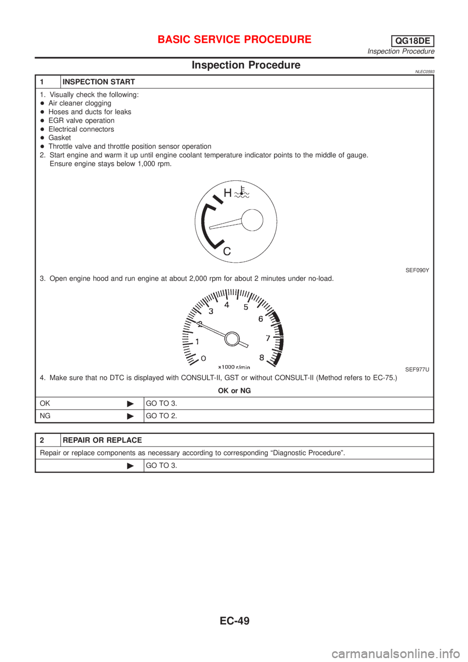
2. Start engine and warm it up until engine coolant temperature indicator points to the middle of gauge.
Ensure engine stays below 1,000 rpm.
SEF090Y
3. Open engine hood and run engine at about 2,000 rpm for about 2 minutes under no-load.
SEF977U
4. Make sure that no DTC is displayed with CONSULT-II, GST or without CONSULT-II (Method refers to EC-75.)
OK or NG
OK©GO TO 3.
NG©GO TO 2.
2 REPAIR OR REPLACE
Repair or replace components as necessary according to corresponding ªDiagnostic Procedureº.
©GO TO 3.
BASIC SERVICE PROCEDUREQG18DE
Inspection Procedure
EC-49
Page 478 of 3051
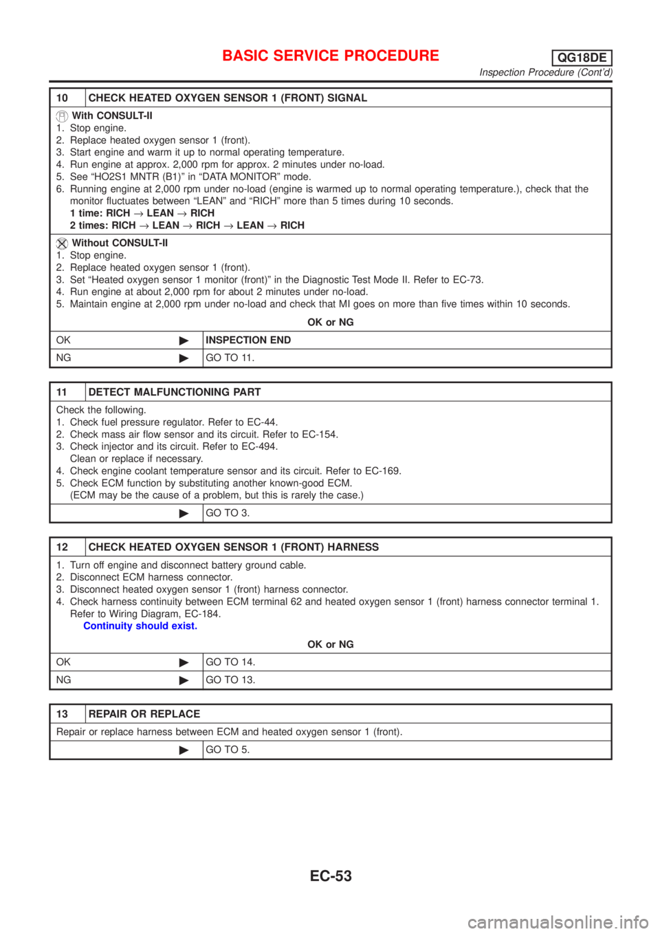
10 CHECK HEATED OXYGEN SENSOR 1 (FRONT) SIGNAL
With CONSULT-II
1. Stop engine.
2. Replace heated oxygen sensor 1 (front).
3. Start engine and warm it up to normal operating temperature.
4. Run engine at approx. 2,000 rpm for approx. 2 minutes under no-load.
5. See ªHO2S1 MNTR (B1)º in ªDATA MONITORº mode.
6. Running engine at 2,000 rpm under no-load (engine is warmed up to normal operating temperature.), check that the
monitor fluctuates between ªLEANº and ªRICHº more than 5 times during 10 seconds.
1 time: RICH®LEAN®RICH
2 times: RICH®LEAN®RICH®LEAN®RICH
Without CONSULT-II
1. Stop engine.
2. Replace heated oxygen sensor 1 (front).
3. Set ªHeated oxygen sensor 1 monitor (front)º in the Diagnostic Test Mode II. Refer to EC-73.
4. Run engine at about 2,000 rpm for about 2 minutes under no-load.
5. Maintain engine at 2,000 rpm under no-load and check that MI goes on more than five times within 10 seconds.
OK or NG
OK©INSPECTION END
NG©GO TO 11.
11 DETECT MALFUNCTIONING PART
Check the following.
1. Check fuel pressure regulator. Refer to EC-44.
2. Check mass air flow sensor and its circuit. Refer to EC-154.
3. Check injector and its circuit. Refer to EC-494.
Clean or replace if necessary.
4. Check engine coolant temperature sensor and its circuit. Refer to EC-169.
5. Check ECM function by substituting another known-good ECM.
(ECM may be the cause of a problem, but this is rarely the case.)
©GO TO 3.
12 CHECK HEATED OXYGEN SENSOR 1 (FRONT) HARNESS
1. Turn off engine and disconnect battery ground cable.
2. Disconnect ECM harness connector.
3. Disconnect heated oxygen sensor 1 (front) harness connector.
4. Check harness continuity between ECM terminal 62 and heated oxygen sensor 1 (front) harness connector terminal 1.
Refer to Wiring Diagram, EC-184.
Continuity should exist.
OK or NG
OK©GO TO 14.
NG©GO TO 13.
13 REPAIR OR REPLACE
Repair or replace harness between ECM and heated oxygen sensor 1 (front).
©GO TO 5.
BASIC SERVICE PROCEDUREQG18DE
Inspection Procedure (Cont'd)
EC-53
Page 479 of 3051
14 PREPARATION FOR ªCOº % CHECK
With CONSULT-II
1. Reconnect ECM harness connector.
2. Turn ignition switch ªONº.
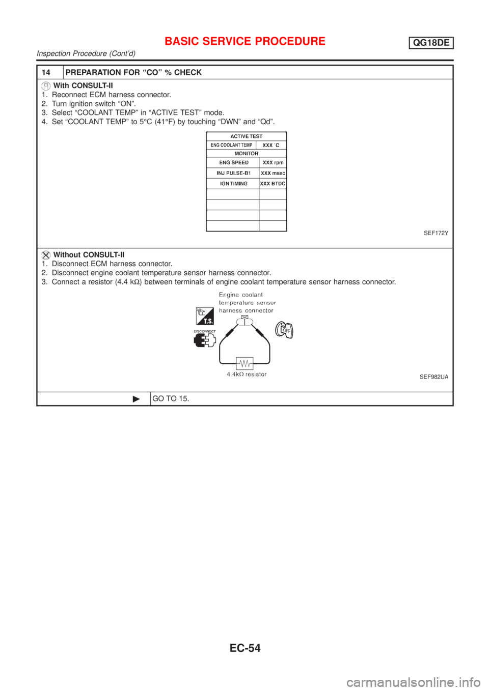
3. Select ªCOOLANT TEMPº in ªACTIVE TESTº mode.
4. Set ªCOOLANT TEMPº to 5ÉC (41ÉF) by touching ªDWNº and ªQdº.
SEF172Y
Without CONSULT-II
1. Disconnect ECM harness connector.
2. Disconnect engine coolant temperature sensor harness connector.
3. Connect a resistor (4.4 kW) between terminals of engine coolant temperature sensor harness connector.
SEF982UA
©GO TO 15.
BASIC SERVICE PROCEDUREQG18DE
Inspection Procedure (Cont'd)
EC-54
Page 480 of 3051
15 CHECK ªCOº %
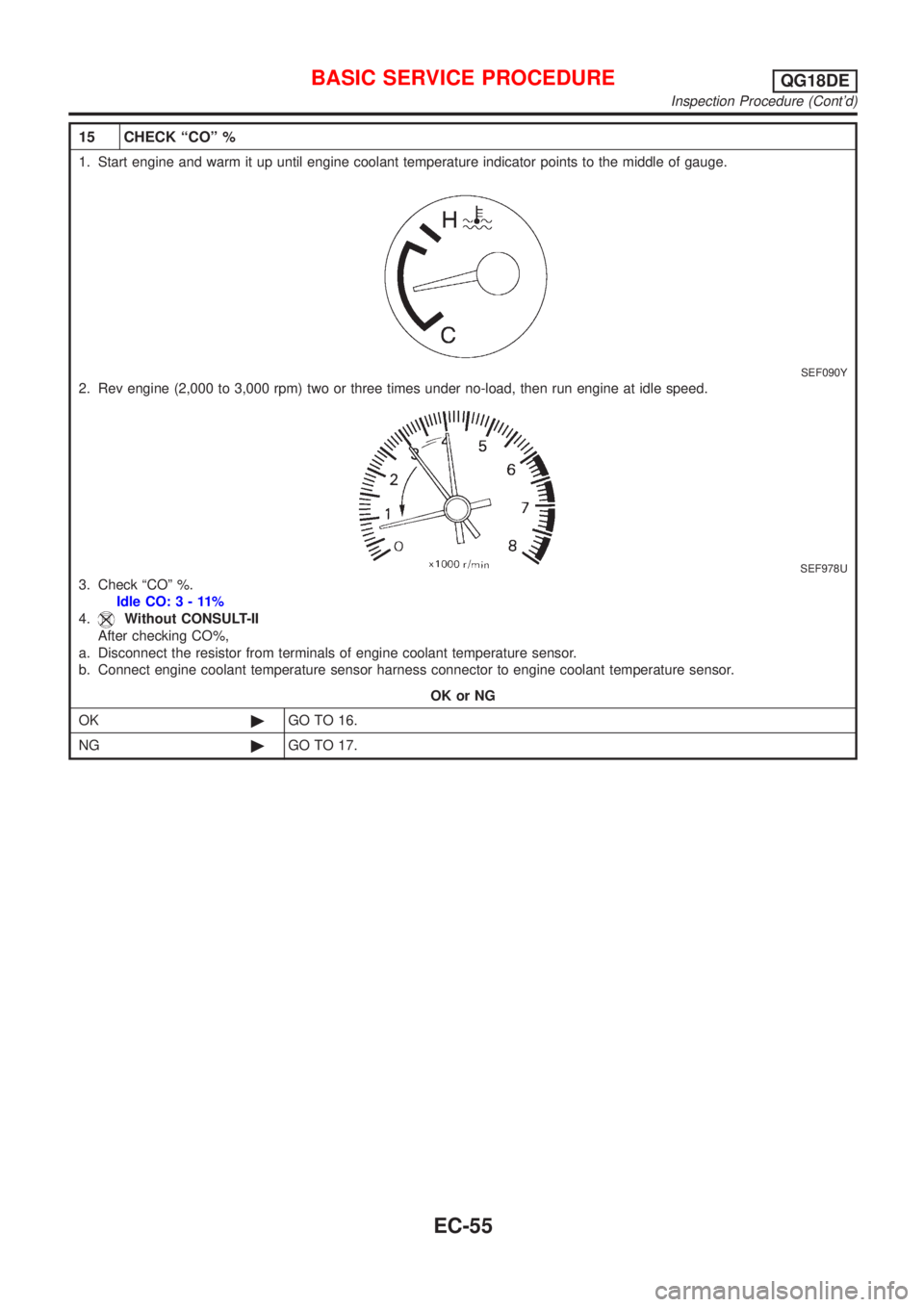
1. Start engine and warm it up until engine coolant temperature indicator points to the middle of gauge.
SEF090Y
2. Rev engine (2,000 to 3,000 rpm) two or three times under no-load, then run engine at idle speed.
SEF978U
3. Check ªCOº %.
Idle CO:3-11%
4.
Without CONSULT-II
After checking CO%,
a. Disconnect the resistor from terminals of engine coolant temperature sensor.
b. Connect engine coolant temperature sensor harness connector to engine coolant temperature sensor.
OK or NG
OK©GO TO 16.
NG©GO TO 17.
BASIC SERVICE PROCEDUREQG18DE
Inspection Procedure (Cont'd)
EC-55
Page 481 of 3051
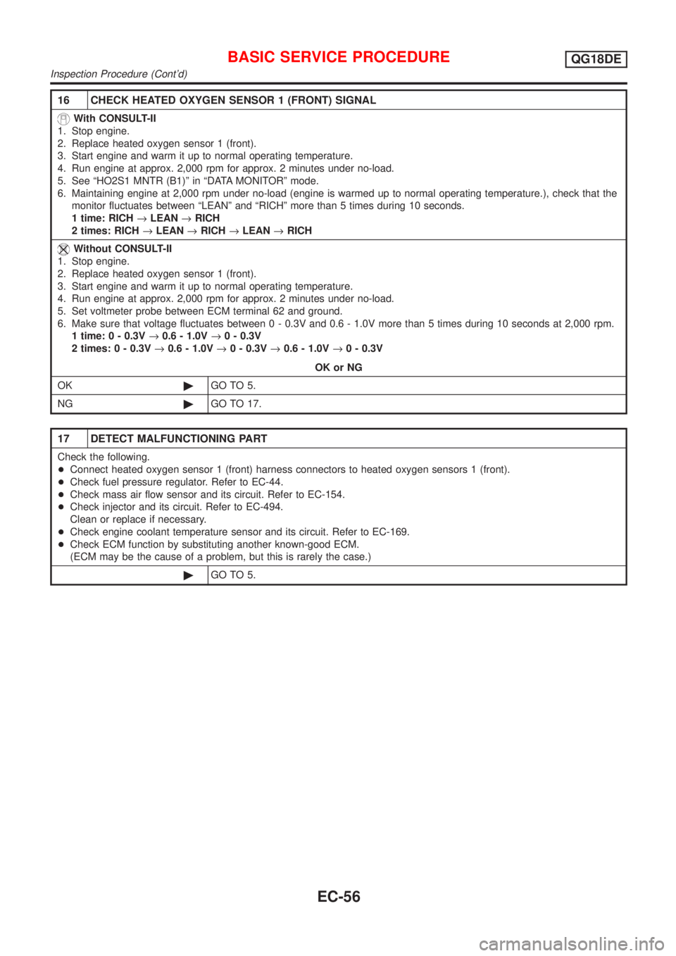
16 CHECK HEATED OXYGEN SENSOR 1 (FRONT) SIGNAL
With CONSULT-II
1. Stop engine.
2. Replace heated oxygen sensor 1 (front).
3. Start engine and warm it up to normal operating temperature.
4. Run engine at approx. 2,000 rpm for approx. 2 minutes under no-load.
5. See ªHO2S1 MNTR (B1)º in ªDATA MONITORº mode.
6. Maintaining engine at 2,000 rpm under no-load (engine is warmed up to normal operating temperature.), check that the
monitor fluctuates between ªLEANº and ªRICHº more than 5 times during 10 seconds.
1 time: RICH®LEAN®RICH
2 times: RICH®LEAN®RICH®LEAN®RICH
Without CONSULT-II
1. Stop engine.
2. Replace heated oxygen sensor 1 (front).
3. Start engine and warm it up to normal operating temperature.
4. Run engine at approx. 2,000 rpm for approx. 2 minutes under no-load.
5. Set voltmeter probe between ECM terminal 62 and ground.
6. Make sure that voltage fluctuates between 0 - 0.3V and 0.6 - 1.0V more than 5 times during 10 seconds at 2,000 rpm.
1 time: 0 - 0.3V®0.6 - 1.0V®0 - 0.3V
2 times: 0 - 0.3V®0.6 - 1.0V®0 - 0.3V®0.6 - 1.0V®0 - 0.3V
OK or NG
OK©GO TO 5.
NG©GO TO 17.
17 DETECT MALFUNCTIONING PART
Check the following.
+Connect heated oxygen sensor 1 (front) harness connectors to heated oxygen sensors 1 (front).
+Check fuel pressure regulator. Refer to EC-44.
+Check mass air flow sensor and its circuit. Refer to EC-154.
+Check injector and its circuit. Refer to EC-494.
Clean or replace if necessary.
+Check engine coolant temperature sensor and its circuit. Refer to EC-169.
+Check ECM function by substituting another known-good ECM.
(ECM may be the cause of a problem, but this is rarely the case.)
©GO TO 5.
BASIC SERVICE PROCEDUREQG18DE
Inspection Procedure (Cont'd)
EC-56
Page 482 of 3051
SEF217Z
SEF454Y
SEF455Y
Idle Air Volume LearningNLEC0562DESCRIPTIONNLEC0562S01ªIdle Air Volume Learningº is an operation to learn the idle air vol-
ume that keeps each engine within the specific range. It must be
performed under any of the following conditions:
+Each time IACV-AAC valve, throttle body or ECM is replaced.
+Idle speed or ignition timing is out of specification.
PRE-CONDITIONINGNLEC0562S02Before performing ªIdle Air Volume Learningº, make sure that all of
the following conditions are satisfied.
Learning will be cancelled if any of the following conditions are
missed for even a moment.
+Battery voltage: More than 12.9V (At idle)
+Engine coolant temperature: 70 - 99ÉC (158 - 210ÉF)
+PNP switch: ON
+Electric load switch: OFF
(Air conditioner, headlamp, rear window defogger)
On vehicles equipped with daytime light systems, set lighting
switch to the 1st position to light only small lamps.
+Cooling fan motor: Not operating
+Steering wheel: Neutral (Straight-ahead position)
+Vehicle speed: Stopped
+Transmission: Warmed-up
M/T models, drive vehicle for 10 minutes.
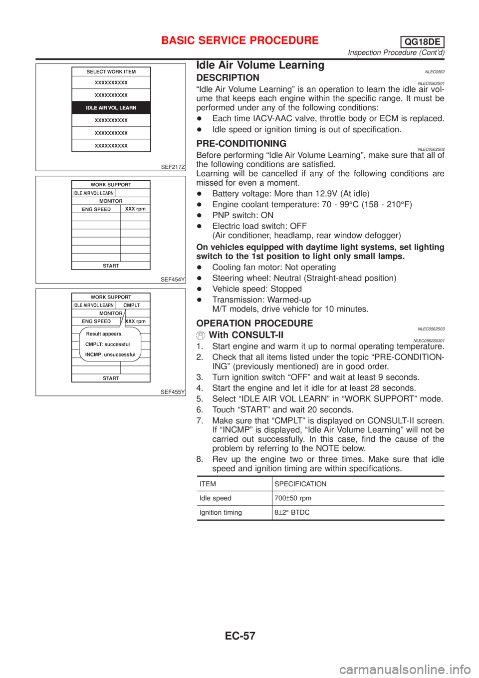
OPERATION PROCEDURENLEC0562S03With CONSULT-IINLEC0562S03011. Start engine and warm it up to normal operating temperature.
2. Check that all items listed under the topic ªPRE-CONDITION-
INGº (previously mentioned) are in good order.
3. Turn ignition switch ªOFFº and wait at least 9 seconds.
4. Start the engine and let it idle for at least 28 seconds.
5. Select ªIDLE AIR VOL LEARNº in ªWORK SUPPORTº mode.
6. Touch ªSTARTº and wait 20 seconds.
7. Make sure that ªCMPLTº is displayed on CONSULT-II screen.
If ªINCMPº is displayed, ªIdle Air Volume Learningº will not be
carried out successfully. In this case, find the cause of the
problem by referring to the NOTE below.
8. Rev up the engine two or three times. Make sure that idle
speed and ignition timing are within specifications.
ITEM SPECIFICATION
Idle speed 700±50 rpm
Ignition timing 8±2É BTDC
BASIC SERVICE PROCEDUREQG18DE
Inspection Procedure (Cont'd)
EC-57