2001 NISSAN ALMERA TINO timing belt
[x] Cancel search: timing beltPage 2321 of 3051
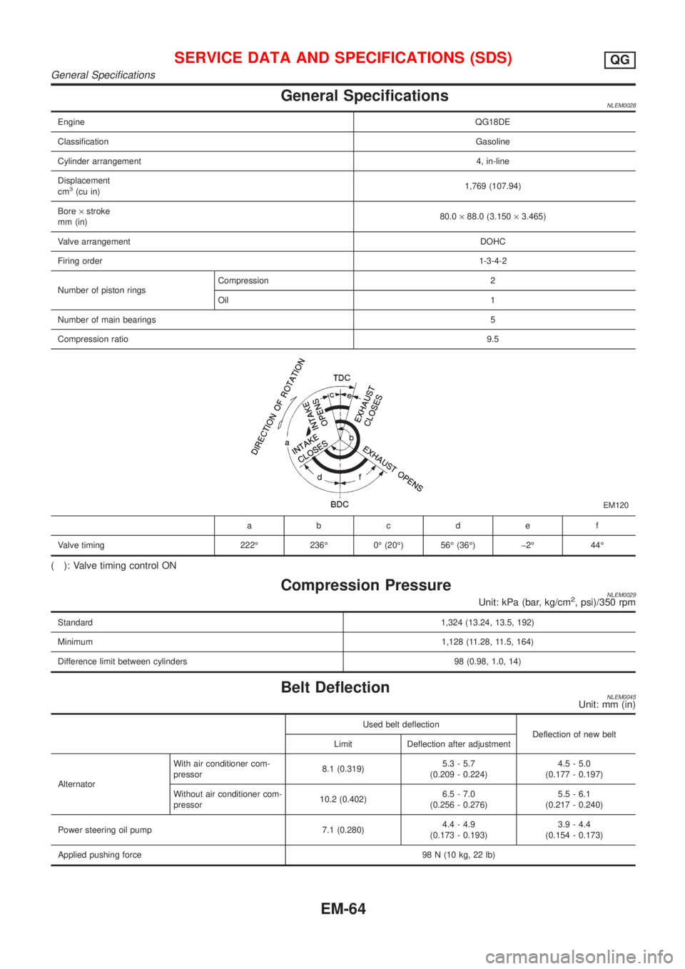
General SpecificationsNLEM0028
EngineQG18DE
ClassificationGasoline
Cylinder arrangement4, in-line
Displacement
cm
3(cu in)1,769 (107.94)
Bore´stroke
mm (in)80.0´88.0 (3.150´3.465)
Valve arrangementDOHC
Firing order1-3-4-2
Number of piston ringsCompression 2
Oil 1
Number of main bearings5
Compression ratio9.5
EM120
abcde f
Valve timing 222É 236É 0É (20É) 56É (36É) þ2É 44É
( ): Valve timing control ON
Compression PressureNLEM0029Unit: kPa (bar, kg/cm2, psi)/350 rpm
Standard1,324 (13.24, 13.5, 192)
Minimum1,128 (11.28, 11.5, 164)
Difference limit between cylinders 98 (0.98, 1.0, 14)
Belt DeflectionNLEM0045Unit: mm (in)
Used belt deflection
Deflection of new belt
Limit Deflection after adjustment
AlternatorWith air conditioner com-
pressor8.1 (0.319)5.3 - 5.7
(0.209 - 0.224)4.5 - 5.0
(0.177 - 0.197)
Without air conditioner com-
pressor10.2 (0.402)6.5 - 7.0
(0.256 - 0.276)5.5 - 6.1
(0.217 - 0.240)
Power steering oil pump 7.1 (0.280)4.4 - 4.9
(0.173 - 0.193)3.9 - 4.4
(0.154 - 0.173)
Applied pushing force98 N (10 kg, 22 lb)
SERVICE DATA AND SPECIFICATIONS (SDS)QG
General Specifications
EM-64
Page 2338 of 3051
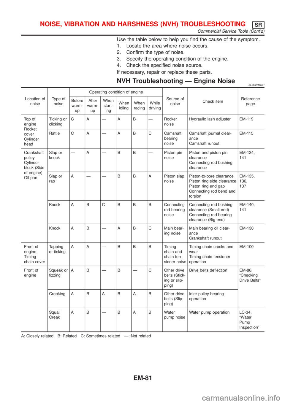
Use the table below to help you find the cause of the symptom.
1. Locate the area where noise occurs.
2. Confirm the type of noise.
3. Specify the operating condition of the engine.
4. Check the specified noise source.
If necessary, repair or replace these parts.
NVH Troubleshooting Ð Engine NoiseNLEM0116S01
Location of
noiseType of
noiseOperating condition of engine
Source of
noiseCheck itemReference
page Before
warm-
upAfter
warm-
upWhen
start-
ingWhen
idlingWhen
racingWhile
driving
To p o f
engine
Rocket
cover
Cylinder
headTicking or
clickingC A Ð A B Ð Rocker
noiseHydraulic lash adjuster EM-119
Rattle C A Ð A B C Camshaft
bearing
noiseCamshaft journal clear-
ance
Camshaft runoutEM-115
Crankshaft
pulley
Cylinder
block (Side
of engine)
Oil panSlap or
knockÐ A Ð B B Ð Piston pin
noisePiston and piston pin
clearance
Connecting rod bushing
clearanceEM-134,
141
Slap or
rapA Ð Ð B B A Piston slap
noisePiston-to-bore clearance
Piston ring side clearance
Piston ring end gap
Connecting rod bend and
torsionEM-135,
136,
137
Knock A B CB B B Connecting
rod bearing
noiseConnecting rod bushing
clearance (Small end)
Connecting rod bearing
clearance (Big end)EM-140,
141
Knock A B Ð A B C Main bear-
ing noiseMain bearing oil clear-
ance
Crankshaft runoutEM-138
Front of
engine
Timing
chain coverTapping
or tickingAAÐBBBTiming
chain and
chain ten-
sioner noiseTiming chain cracks and
wear
Timing chain tensioner
operationEM-100
Front of
engineSqueak or
fizzingA B Ð B Ð C Other drive
belts (Stick-
ing or slip-
ping)Drive belts deflection EM-86,
ªChecking
Drive Beltsº
CreakingABABABOther drive
belts (Slip-
ping)Idler pulley bearing
operation
Squall
CreakABÐBABWater
pump noiseWater pump operation LC-34,
ªWater
Pump
Inspectionº
A: Closely related B: Related C: Sometimes related Ð: Not related
NOISE, VIBRATION AND HARSHNESS (NVH) TROUBLESHOOTINGSR
Commercial Service Tools (Cont'd)
EM-81
Page 2354 of 3051
CAUTION:
+After removing timing chain, do not turn crankshaft and
camshaft separately, or valves will strike piston heads.
+When installing chain tensioner, oil seals, or other sliding
parts, lubricate contacting surfaces with new engine oil.
+Apply new engine oil to bolt threads and seat surfaces
when installing camshaft sprocket and crankshaft pulley.
RemovalNLEM01261. Remove engine under cover.
2. Remove front RH wheel and engine side cover.
3. Drain coolant by removing cylinder block drain plug and lower
radiator hose. Refer to LC-38, ªChanging Engine Coolantº.
4. Remove drive belts and water pump pulley.
5. Disconnect the following parts:
+Vacuum hoses
+Wires
+Harness
+Connectors
SEM029G
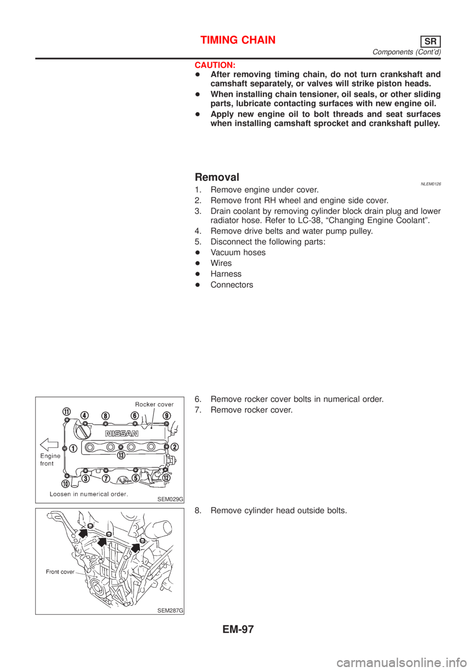
6. Remove rocker cover bolts in numerical order.
7. Remove rocker cover.
SEM287G
8. Remove cylinder head outside bolts.
TIMING CHAINSR
Components (Cont'd)
EM-97
Page 2361 of 3051
BEM006
SEM051G
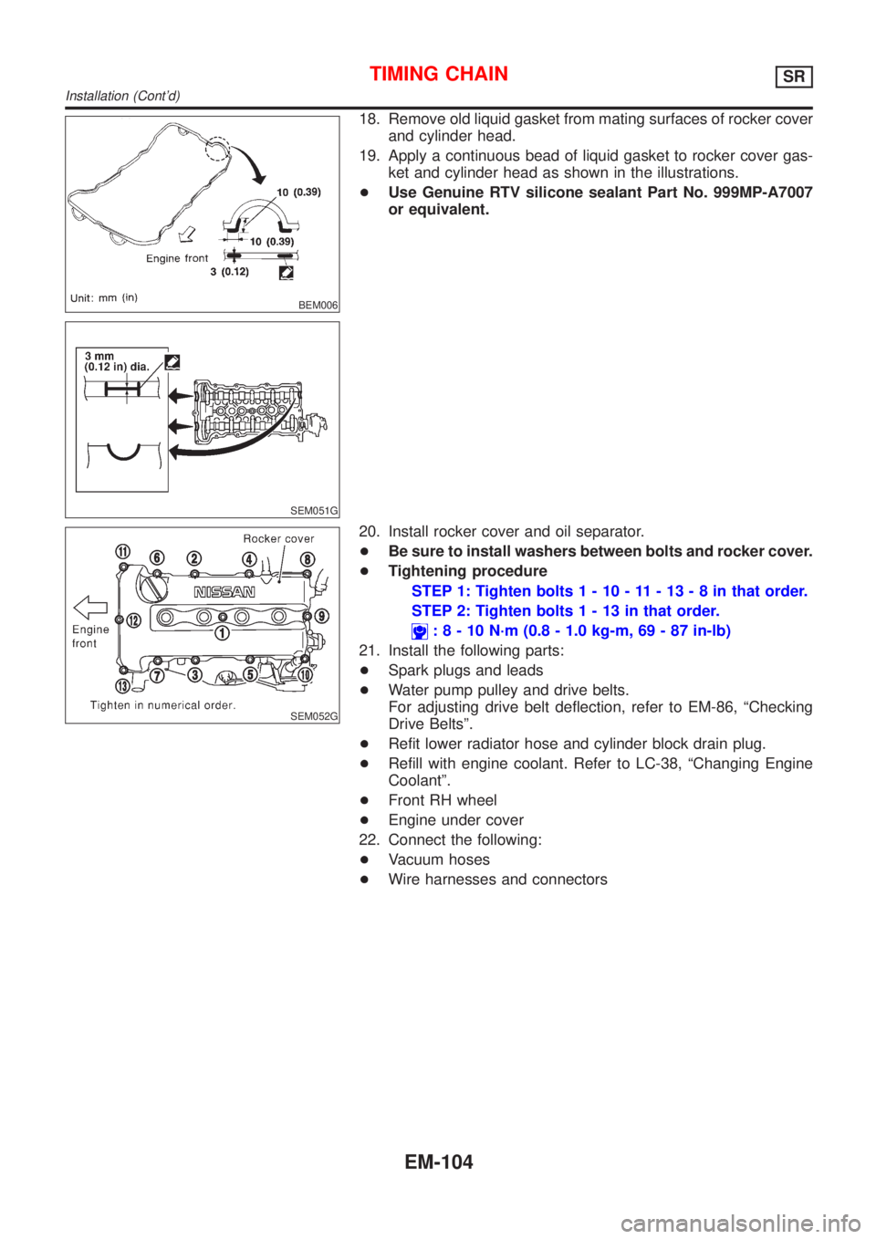
18. Remove old liquid gasket from mating surfaces of rocker cover
and cylinder head.
19. Apply a continuous bead of liquid gasket to rocker cover gas-
ket and cylinder head as shown in the illustrations.
+Use Genuine RTV silicone sealant Part No. 999MP-A7007
or equivalent.
SEM052G
20. Install rocker cover and oil separator.
+Be sure to install washers between bolts and rocker cover.
+Tightening procedure
STEP 1: Tighten bolts1-10-11-13-8inthat order.
STEP 2: Tighten bolts1-13inthat order.
:8-10N´m(0.8 - 1.0 kg-m, 69 - 87 in-lb)
21. Install the following parts:
+Spark plugs and leads
+Water pump pulley and drive belts.
For adjusting drive belt deflection, refer to EM-86, ªChecking
Drive Beltsº.
+Refit lower radiator hose and cylinder block drain plug.
+Refill with engine coolant. Refer to LC-38, ªChanging Engine
Coolantº.
+Front RH wheel
+Engine under cover
22. Connect the following:
+Vacuum hoses
+Wire harnesses and connectors
TIMING CHAINSR
Installation (Cont'd)
EM-104
Page 2420 of 3051
NLEM0051
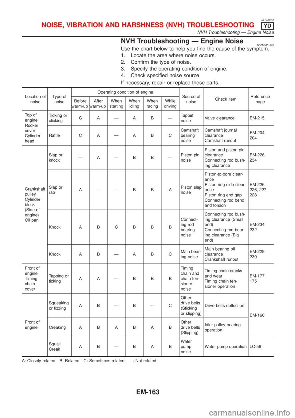
NVH Troubleshooting Ð Engine NoiseNLEM0051S01Use the chart below to help you find the cause of the symptom.
1. Locate the area where noise occurs.
2. Confirm the type of noise.
3. Specify the operating condition of engine.
4. Check specified noise source.
If necessary, repair or replace these parts.
Location of
noiseType of
noiseOperating condition of engine
Source of
noiseCheck itemReference
page Before
warm-upAfter
warm-upWhen
startingWhen
idlingWhen
racingWhile
driving
To p o f
engine
Rocker
cover
Cylinder
headTicking or
clickingC AÐA BÐTappet
noiseValve clearance EM-215
Rattle C A Ð A B CCamshaft
bearing
noiseCamshaft journal
clearance
Camshaft runoutEM-204,
204
Crankshaft
pulley
Cylinder
block
(Side of
engine)
Oil panSlap or
knockÐAÐB BÐPiston pin
noisePiston and piston pin
clearance
Connecting rod bush-
ing clearanceEM-226,
234
Slap or
rapAÐÐB B APiston slap
noisePiston-to-bore clear-
ance
Piston ring side clear-
ance
Piston ring end gap
Connecting rod bend
and torsionEM-226,
226, 227,
228
Knock A B C B B BConnect-
ing rod
bearing
noiseConnecting rod bush-
ing clearance (Small
end)
Connecting rod bear-
ing clearance (Big
end)EM-234,
232
Knock A B Ð A B CMain bear-
ing noiseMain bearing oil
clearance
Crankshaft runoutEM-229,
230
Front of
engine
Timing
chain
coverTapping or
tickingAAÐBBBTiming
chain and
chain ten-
sioner
noiseTiming chain cracks
and wear
Timing chain ten-
sioner operationEM-177,
175
Front of
engineSqueaking
or fizzingA BÐBÐCOther
drive belts
(Sticking
or slipping)Drive belts deflection
EM-166
CreakingABABABOther
drive belts
(Slipping)Idler pulley bearing
operation
Squall
CreakABÐBABWater
pump
noiseWater pump operation LC-56
A: Closely related B: Related C: Sometimes related Ð: Not related
NOISE, VIBRATION AND HARSHNESS (NVH) TROUBLESHOOTINGYD
NVH Troubleshooting Ð Engine Noise
EM-163
Page 2702 of 3051

S
S/LOCK - Wiring diagram ................ EL-260, 286
S/SIG - Wiring diagram ................. EC-512, 1028
SAE J1930 terminology list ........................ GI-48
SHIFT - Wiring diagram ........................... AT-196
SROOF - Wiring diagram ........................ EL-238
SRS - See Supplemental Restraint
System ................................................... RS-16
START - Wiring diagram ........................... SC-14
STOP/L - Wiring diagram .......................... EL-91
SWL/V - Wiring diagram ................. EC-366, 481
Seal - See Exterior .................................... BT-38
Seat belt pre-tensioner disposal ............... RS-30
Seat belt pre-tensioner ............................... RS-3
Seat belt, front ............................................ RS-5
Seat belt, rear ............................................. RS-7
Seat, front .................................................. BT-46
Seat, rear ................................................... BT-49
Self-diagnostic results ............ EC-73, 598, 1098
Shift control components (M/T) .......... MT-26, 64
Shift fork (M/T) .................................... MT-26, 64
Shift lever .................................................. MT-23
Shift lock system ...................................... AT-195
Shock absorber (front) .............................. SU-11
Shock absorber (rear) ............................... SU-23
Side air bag ............................................... RS-28
Side trim .................................................... BT-28
Speedometer ........................................... EL-130
Spiral cable ............................................... RS-24
Spring (Wheelarch) height .......................... SU-6
Stabilizer bar (front) .................................. SU-12
Stall test (A/T) ............................................ AT-51
Standardized relay ....................................... EL-7
Start signal .......................... EC-511, 1027, 1293
Starter ....................................................... SC-17
Starting system ......................................... SC-13
Steering linkage ......................................... ST-15
Steering switch .......................................... EL-67
Steering wheel and column ....................... ST-10
Steering wheel play ..................................... ST-6
Steering wheel turning force ....................... ST-8
Stop lamp .................................................. EL-91
Striking rod (M/T) ................................ MT-26, 64
Strut (front) ................................................ SU-10
Strut (rear) ................................................. SU-22
Sub-gear (M/T) .......................................... MT-25
Sunroof, electric ....................................... EL-238
Sunroof ...................................................... BT-51
Super lock ................................................ EL-281
Supplemental Restraint System ............... RS-16
Swirl control valve control solenoid
valve .................................. EC-366, 481, 1285
Symbols and abbreviations .......................... GI-9
Symptom matrix chart ........... EC-124, 648, 1116
Synchronizer (M/T) ............................. MT-25, 63
System readiness test (SRT) code ... EC-62, 586
T
TCM circuit diagram ................................... AT-13
TCM inspection table ................................. AT-58
TP/SW - Wiring diagram ................. EC-354, 874
TPS - Wiring diagram ..................... EC-178, 703
TURN - Wiring diagram ........................... EL-102
Tachometer .............................................. EL-130
Tail lamp .................................................... EL-87
Thermostat .................................... LC-15, 35, 57
Three way catalyst precautions ................... GI-6
Three way catalyst .......................... EC-327, 848
Throttle position sensor (TPS) ........ EC-175, 700
Throttle position sensor adjustment .. EC-99, 623
Throttle position switch ................... AT-111, 145,
EC-352, 872
Throwout bearing - See Clutch release
bearing ............................................. CL-17, 20
Tie-rod ball joints ....................................... ST-18
Tie-rod ........................................................ ST-15
Tightening torque of standard bolts ........... GI-47
Timing belt .......................................... EM-22, 96
Timing chain ........................................... EM-175
Tire size ...................................................... GI-41
Torque converter installation .................... AT-207
Tow truck towing ........................................ GI-45
Transmission case (M/T) .................... MT-24, 62
Tread-FR&RR (Dimensions) ...................... GI-41
Trim ............................................................ BT-28
Trouble diagnoses ...................................... GI-31
Trunk lid finisher ........................................ BT-31
Trunk lid opener - See Trunk lid ................ BT-10
Trunk lid trim .............................................. BT-31
Trunk lid ..................................................... BT-10
Trunk room trim ......................................... BT-31
Turn signal lamp ...................................... EL-101
Two trip detection logic ..................... EC-59, 583
Two-pole lift ................................................ GI-44
U
Under body ................................................ BT-68
V
VSS - Wiring diagram ........... EC-340, 860, 1172
Vacuum hose (brake system) ................... BR-18
Vacuum hose drawing (Engine control) ... EC-33,
567, 1077
Vacuum pump ........................................... BR-20
Valve clearance ................................ EM-42, 214
Valve guide ............................... EM-38, 116, 205
Valve lifter ................................................. EM-41
Valve seat ................................. EM-40, 117, 207
Valve spring .............................. EM-41, 119, 209
ALPHABETICAL INDEX
IDX-7
Page 2708 of 3051
SEM853F
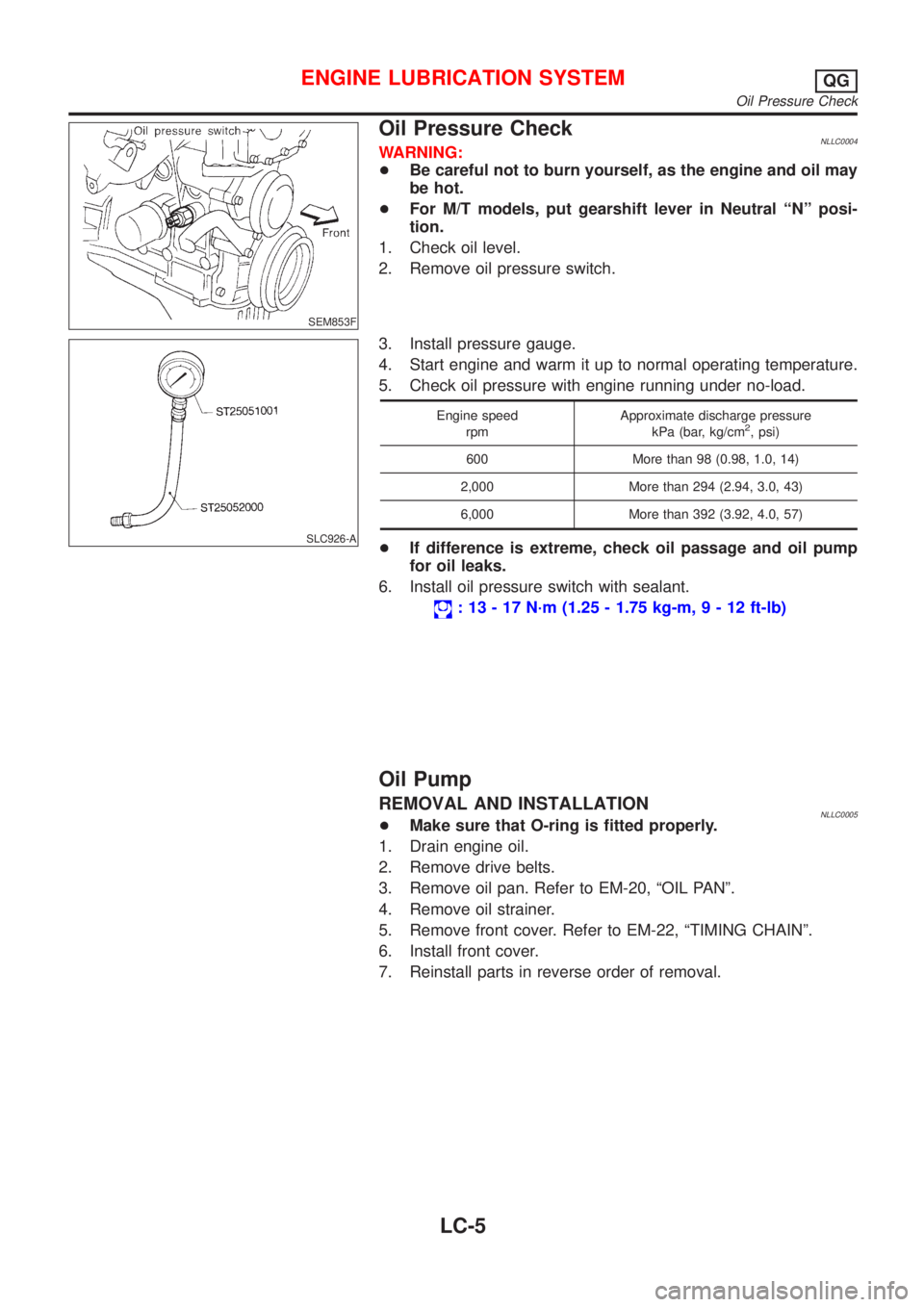
Oil Pressure CheckNLLC0004WARNING:
+Be careful not to burn yourself, as the engine and oil may
be hot.
+For M/T models, put gearshift lever in Neutral ªNº posi-
tion.
1. Check oil level.
2. Remove oil pressure switch.
SLC926-A
3. Install pressure gauge.
4. Start engine and warm it up to normal operating temperature.
5. Check oil pressure with engine running under no-load.
Engine speed
rpmApproximate discharge pressure
kPa (bar, kg/cm2, psi)
600 More than 98 (0.98, 1.0, 14)
2,000 More than 294 (2.94, 3.0, 43)
6,000 More than 392 (3.92, 4.0, 57)
+If difference is extreme, check oil passage and oil pump
for oil leaks.
6. Install oil pressure switch with sealant.
: 13 - 17 N´m (1.25 - 1.75 kg-m,9-12ft-lb)
Oil Pump
REMOVAL AND INSTALLATIONNLLC0005+Make sure that O-ring is fitted properly.
1. Drain engine oil.
2. Remove drive belts.
3. Remove oil pan. Refer to EM-20, ªOIL PANº.
4. Remove oil strainer.
5. Remove front cover. Refer to EM-22, ªTIMING CHAINº.
6. Install front cover.
7. Reinstall parts in reverse order of removal.
ENGINE LUBRICATION SYSTEMQG
Oil Pressure Check
LC-5
Page 2728 of 3051
NLC045
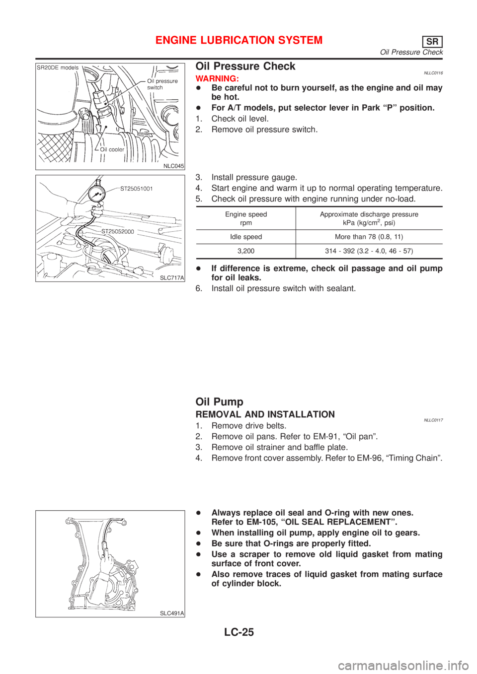
Oil Pressure CheckNLLC0116WARNING:
+Be careful not to burn yourself, as the engine and oil may
be hot.
+For A/T models, put selector lever in Park ªPº position.
1. Check oil level.
2. Remove oil pressure switch.
SLC717A
3. Install pressure gauge.
4. Start engine and warm it up to normal operating temperature.
5. Check oil pressure with engine running under no-load.
Engine speed
rpmApproximate discharge pressure
kPa (kg/cm2, psi)
Idle speed More than 78 (0.8, 11)
3,200 314 - 392 (3.2 - 4.0, 46 - 57)
+If difference is extreme, check oil passage and oil pump
for oil leaks.
6. Install oil pressure switch with sealant.
Oil Pump
REMOVAL AND INSTALLATIONNLLC01171. Remove drive belts.
2. Remove oil pans. Refer to EM-91, ªOil panº.
3. Remove oil strainer and baffle plate.
4. Remove front cover assembly. Refer to EM-96, ªTiming Chainº.
SLC491A
+Always replace oil seal and O-ring with new ones.
Refer to EM-105, ªOIL SEAL REPLACEMENTº.
+When installing oil pump, apply engine oil to gears.
+Be sure that O-rings are properly fitted.
+Use a scraper to remove old liquid gasket from mating
surface of front cover.
+Also remove traces of liquid gasket from mating surface
of cylinder block.
ENGINE LUBRICATION SYSTEMSR
Oil Pressure Check
LC-25