2001 NISSAN ALMERA TINO air conditioning
[x] Cancel search: air conditioningPage 997 of 3051
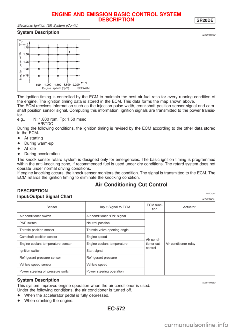
System DescriptionNLEC1343S02
SEF742M
The ignition timing is controlled by the ECM to maintain the best air-fuel ratio for every running condition of
the engine. The ignition timing data is stored in the ECM. This data forms the map shown above.
The ECM receives information such as the injection pulse width, crankshaft position sensor signal and cam-
shaft position sensor signal. Computing this information, ignition signals are transmitted to the power transis-
tor.
e.g., N: 1,800 rpm, Tp: 1.50 msec
AÉBTDC
During the following conditions, the ignition timing is revised by the ECM according to the other data stored
in the ECM.
+At starting
+During warm-up
+At idle
+During acceleration
The knock sensor retard system is designed only for emergencies. The basic ignition timing is programmed
within the anti-knocking zone, if recommended fuel is used under dry conditions. The retard system does not
operate under normal driving conditions.
If engine knocking occurs, the knock sensor monitors the condition. The signal is transmitted to the ECM. The
ECM retards the ignition timing to eliminate the knocking condition.
Air Conditioning Cut Control
DESCRIPTIONNLEC1344Input/Output Signal ChartNLEC1344S01
Sensor Input Signal to ECMECM func-
tionActuator
Air conditioner switch Air conditioner ªONº signal
Air condi-
tioner cut
controlAir conditioner relay PNP switch Neutral position
Throttle position sensor Throttle valve opening angle
Camshaft position sensor Engine speed
Engine coolant temperature sensor Engine coolant temperature
Ignition switch Start signal
Refrigerant pressure sensor Refrigerant pressure
Vehicle speed sensor Vehicle speed
Power steering oil pressure switch Power steering operation
System DescriptionNLEC1344S02This system improves engine operation when the air conditioner is used.
Under the following conditions, the air conditioner is turned off.
+When the accelerator pedal is fully depressed.
+When cranking the engine.
ENGINE AND EMISSION BASIC CONTROL SYSTEM
DESCRIPTION
SR20DE
Electronic Ignition (EI) System (Cont'd)
EC-572
Page 998 of 3051
+At high engine speeds.
+When the engine coolant temperature becomes excessively high.
+When operating power steering during low engine speed or low vehicle speed.
+When engine speed is excessively low.
+When the refrigerant pressure is excessively high or low.
Fuel Cut Control (at no load & high engine
speed)
DESCRIPTIONNLEC1345Input/Output Signal ChartNLEC1345S01
Sensor Input Signal to ECMECM func-
tionActuator
Vehicle speed sensor Vehicle speed
Fuel cut
controlInjectors PNP switch Neutral position
Throttle position sensor Throttle position
Engine coolant temperature sensor Engine coolant temperature
Camshaft position sensor Engine speed
If the engine speed is above 3,950 rpm with no load, (for example, in Neutral and engine speed over 4,000
rpm) fuel will be cut off after some time. The exact time when the fuel is cut off varies based on engine speed.
Fuel cut will operate until the engine speed reaches 1,150 rpm, then fuel cut is cancelled.
NOTE:
This function is different from deceleration control listed under ªMultiport Fuel Injection (MFI) Systemº,
EC-569.
Evaporative Emission System
DESCRIPTIONNLEC1346
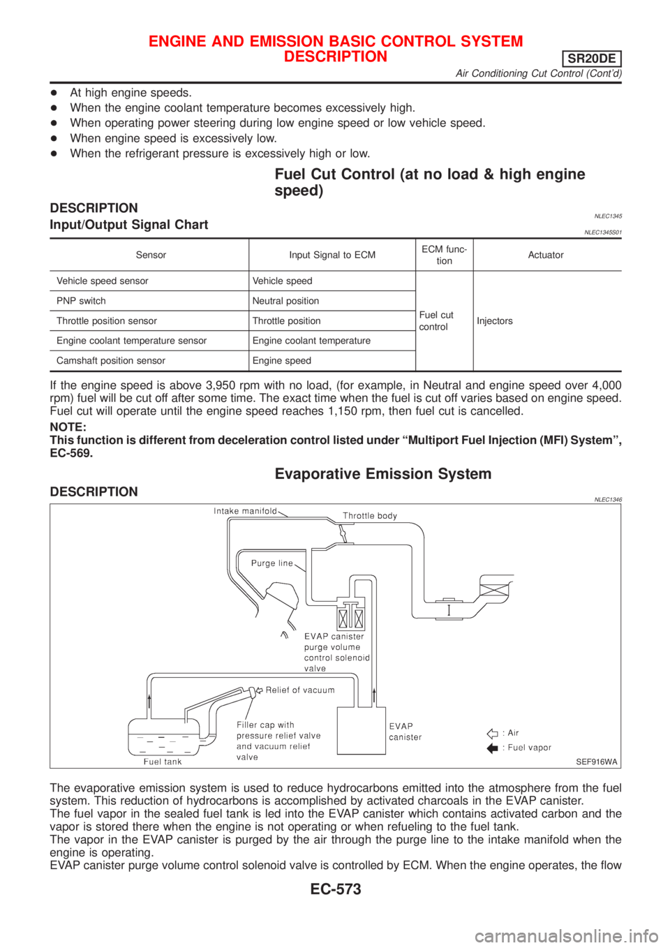
SEF916WA
The evaporative emission system is used to reduce hydrocarbons emitted into the atmosphere from the fuel
system. This reduction of hydrocarbons is accomplished by activated charcoals in the EVAP canister.
The fuel vapor in the sealed fuel tank is led into the EVAP canister which contains activated carbon and the
vapor is stored there when the engine is not operating or when refueling to the fuel tank.
The vapor in the EVAP canister is purged by the air through the purge line to the intake manifold when the
engine is operating.
EVAP canister purge volume control solenoid valve is controlled by ECM. When the engine operates, the flow
ENGINE AND EMISSION BASIC CONTROL SYSTEM
DESCRIPTION
SR20DE
Air Conditioning Cut Control (Cont'd)
EC-573
Page 1006 of 3051
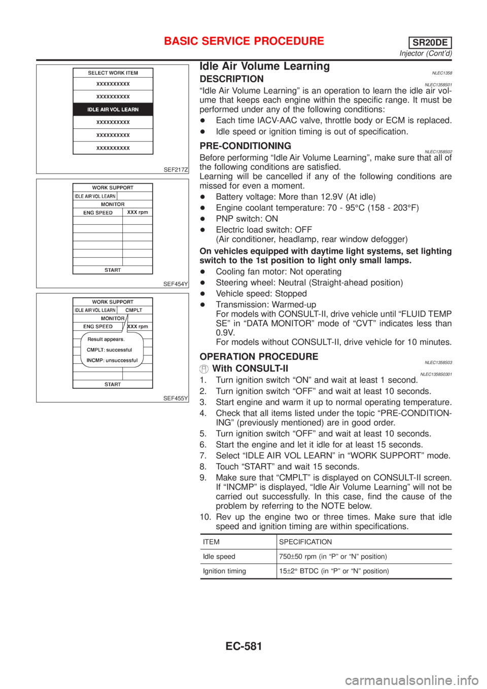
SEF217Z
SEF454Y
SEF455Y
Idle Air Volume LearningNLEC1358DESCRIPTIONNLEC1358S01ªIdle Air Volume Learningº is an operation to learn the idle air vol-
ume that keeps each engine within the specific range. It must be
performed under any of the following conditions:
+Each time IACV-AAC valve, throttle body or ECM is replaced.
+Idle speed or ignition timing is out of specification.
PRE-CONDITIONINGNLEC1358S02Before performing ªIdle Air Volume Learningº, make sure that all of
the following conditions are satisfied.
Learning will be cancelled if any of the following conditions are
missed for even a moment.
+Battery voltage: More than 12.9V (At idle)
+Engine coolant temperature: 70 - 95ÉC (158 - 203ÉF)
+PNP switch: ON
+Electric load switch: OFF
(Air conditioner, headlamp, rear window defogger)
On vehicles equipped with daytime light systems, set lighting
switch to the 1st position to light only small lamps.
+Cooling fan motor: Not operating
+Steering wheel: Neutral (Straight-ahead position)
+Vehicle speed: Stopped
+Transmission: Warmed-up
For models with CONSULT-II, drive vehicle until ªFLUID TEMP
SEº in ªDATA MONITORº mode of ªCVTº indicates less than
0.9V.
For models without CONSULT-II, drive vehicle for 10 minutes.
OPERATION PROCEDURENLEC1358S03With CONSULT-IINLEC1358S03011. Turn ignition switch ªONº and wait at least 1 second.
2. Turn ignition switch ªOFFº and wait at least 10 seconds.
3. Start engine and warm it up to normal operating temperature.
4. Check that all items listed under the topic ªPRE-CONDITION-
INGº (previously mentioned) are in good order.
5. Turn ignition switch ªOFFº and wait at least 10 seconds.
6. Start the engine and let it idle for at least 15 seconds.
7. Select ªIDLE AIR VOL LEARNº in ªWORK SUPPORTº mode.
8. Touch ªSTARTº and wait 15 seconds.
9. Make sure that ªCMPLTº is displayed on CONSULT-II screen.
If ªINCMPº is displayed, ªIdle Air Volume Learningº will not be
carried out successfully. In this case, find the cause of the
problem by referring to the NOTE below.
10. Rev up the engine two or three times. Make sure that idle
speed and ignition timing are within specifications.
ITEM SPECIFICATION
Idle speed 750±50 rpm (in ªPº or ªNº position)
Ignition timing 15±2É BTDC (in ªPº or ªNº position)
BASIC SERVICE PROCEDURESR20DE
Injector (Cont'd)
EC-581
Page 1503 of 3051
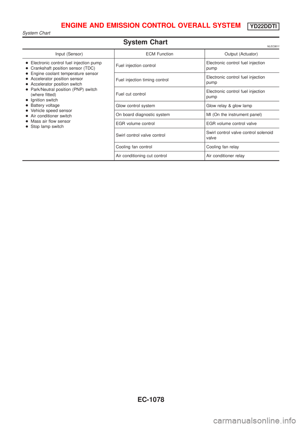
System ChartNLEC0611
Input (Sensor) ECM Function Output (Actuator)
+Electronic control fuel injection pump
+Crankshaft position sensor (TDC)
+Engine coolant temperature sensor
+Accelerator position sensor
+Accelerator position switch
+Park/Neutral position (PNP) switch
(where fitted)
+Ignition switch
+Battery voltage
+Vehicle speed sensor
+Air conditioner switch
+Mass air flow sensor
+Stop lamp switchFuel injection controlElectronic control fuel injection
pump
Fuel injection timing controlElectronic control fuel injection
pump
Fuel cut controlElectronic control fuel injection
pump
Glow control system Glow relay & glow lamp
On board diagnostic system MI (On the instrument panel)
EGR volume control EGR volume control valve
Swirl control valve controlSwirl control valve control solenoid
valve
Cooling fan control Cooling fan relay
Air conditioning cut control Air conditioner relay
ENGINE AND EMISSION CONTROL OVERALL SYSTEMYD22DDTI
System Chart
EC-1078
Page 1506 of 3051
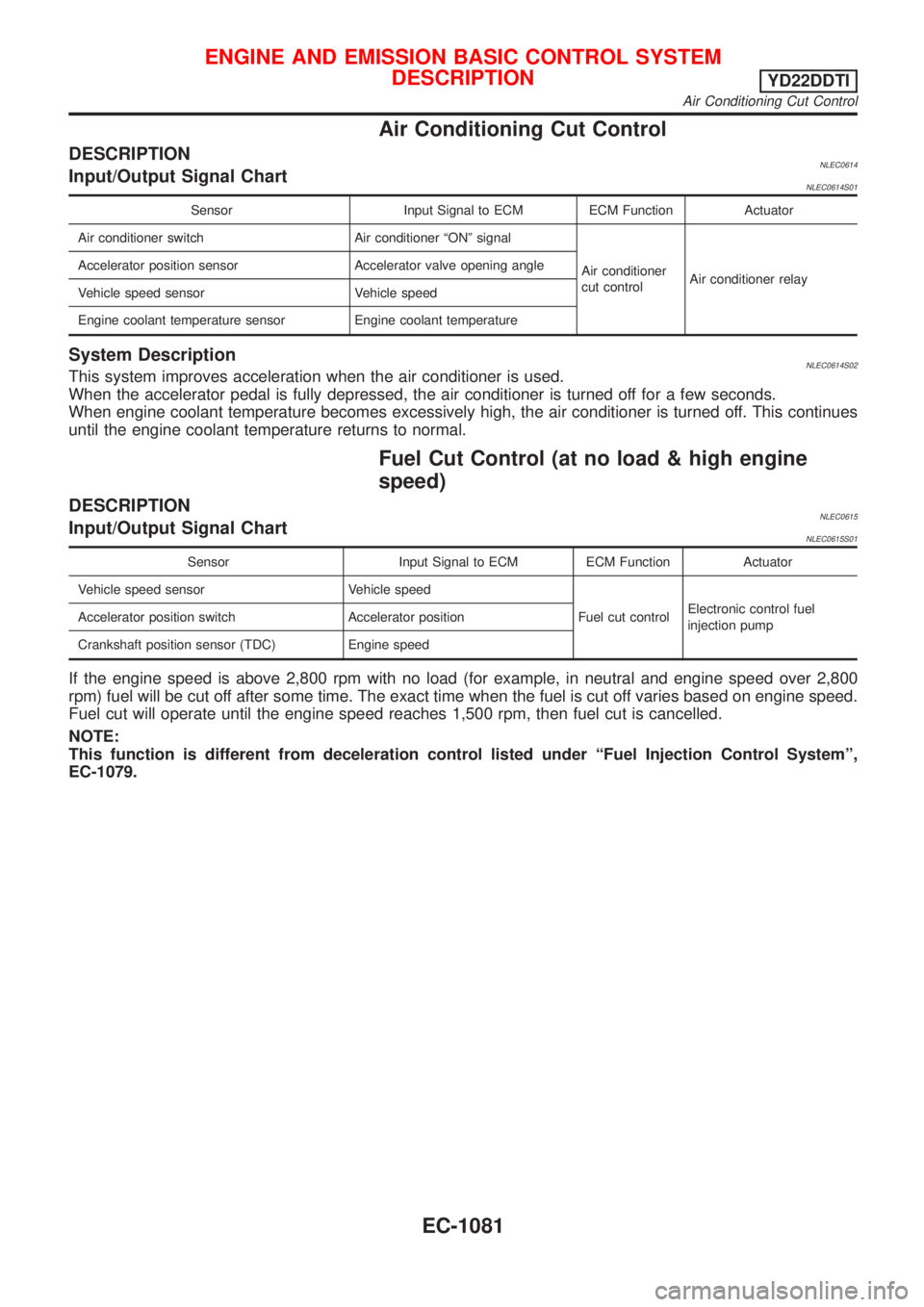
Air Conditioning Cut Control
DESCRIPTIONNLEC0614Input/Output Signal ChartNLEC0614S01
Sensor Input Signal to ECM ECM Function Actuator
Air conditioner switch Air conditioner ªONº signal
Air conditioner
cut controlAir conditioner relay Accelerator position sensor Accelerator valve opening angle
Vehicle speed sensor Vehicle speed
Engine coolant temperature sensor Engine coolant temperature
System DescriptionNLEC0614S02This system improves acceleration when the air conditioner is used.
When the accelerator pedal is fully depressed, the air conditioner is turned off for a few seconds.
When engine coolant temperature becomes excessively high, the air conditioner is turned off. This continues
until the engine coolant temperature returns to normal.
Fuel Cut Control (at no load & high engine
speed)
DESCRIPTIONNLEC0615Input/Output Signal ChartNLEC0615S01
Sensor Input Signal to ECM ECM Function Actuator
Vehicle speed sensor Vehicle speed
Fuel cut controlElectronic control fuel
injection pump Accelerator position switch Accelerator position
Crankshaft position sensor (TDC) Engine speed
If the engine speed is above 2,800 rpm with no load (for example, in neutral and engine speed over 2,800
rpm) fuel will be cut off after some time. The exact time when the fuel is cut off varies based on engine speed.
Fuel cut will operate until the engine speed reaches 1,500 rpm, then fuel cut is cancelled.
NOTE:
This function is different from deceleration control listed under ªFuel Injection Control Systemº,
EC-1079.
ENGINE AND EMISSION BASIC CONTROL SYSTEM
DESCRIPTION
YD22DDTI
Air Conditioning Cut Control
EC-1081
Page 2450 of 3051
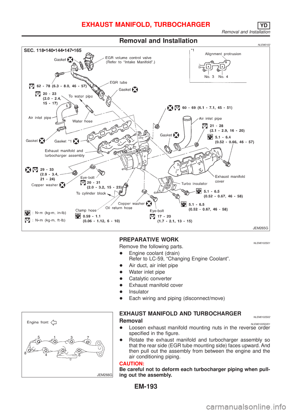
Removal and InstallationNLEM0102
JEM265G
PREPARATIVE WORKNLEM0102S01Remove the following parts.
+Engine coolant (drain)
Refer to LC-59, ªChanging Engine Coolantº.
+Air duct, air inlet pipe
+Water inlet pipe
+Catalytic converter
+Exhaust manifold cover
+Insulator
+Each wiring and piping (disconnect/move)
JEM266G
EXHAUST MANIFOLD AND TURBOCHARGERNLEM0102S02RemovalNLEM0102S0201+Loosen exhaust manifold mounting nuts in the reverse order
specified in the figure.
+Rotate the exhaust manifold and turbocharger assembly so
that the rear side (EGR tube mounting side) faces upward. And
then pull out the assembly from between the engine and the
air conditioning piping.
CAUTION:
Be careful not to deform each turbocharger piping when pull-
ing out the assembly.
EXHAUST MANIFOLD, TURBOCHARGERYD
Removal and Installation
EM-193
Page 2540 of 3051
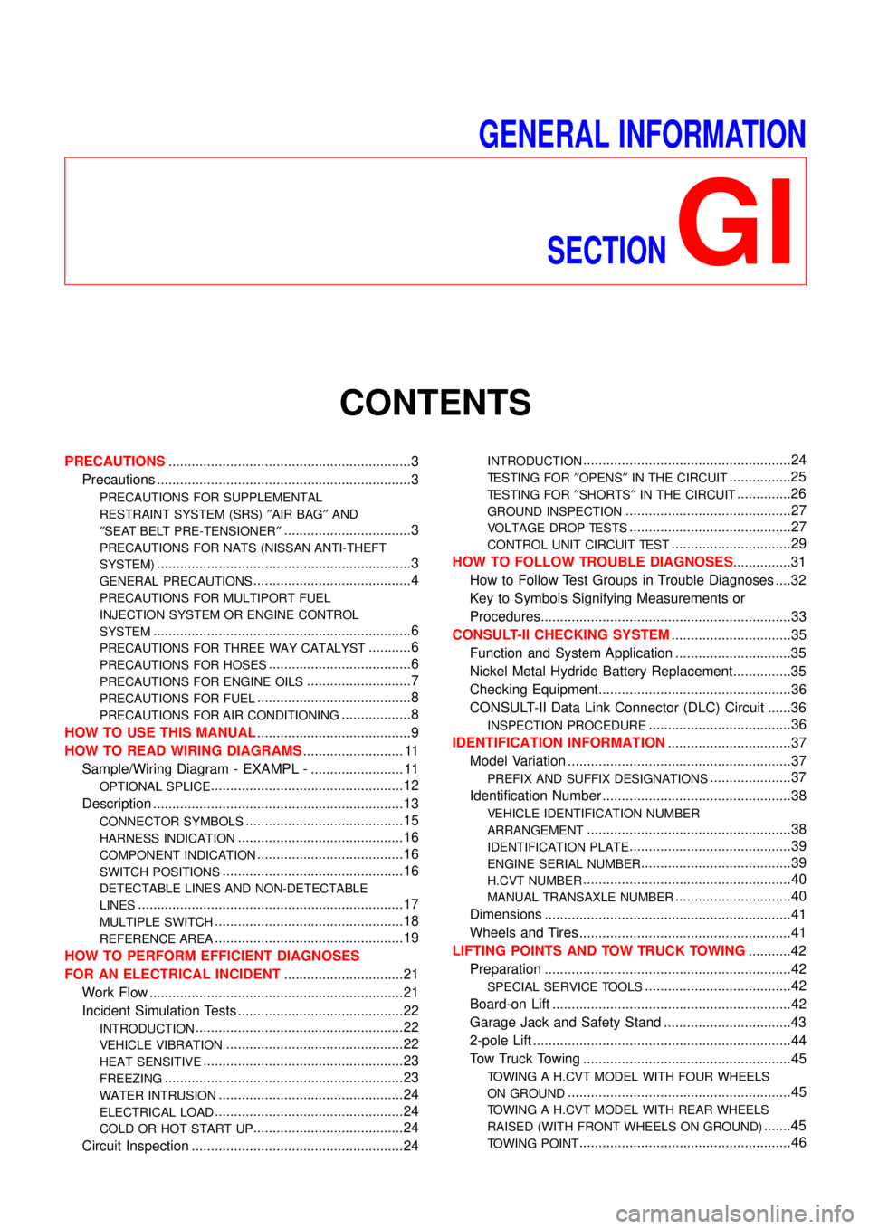
GENERAL INFORMATION
SECTION
GI
CONTENTS
PRECAUTIONS...............................................................3
Precautions ..................................................................3
PRECAUTIONS FOR SUPPLEMENTAL
RESTRAINT SYSTEM (SRS)″AIR BAG″AND
″SEAT BELT PRE-TENSIONER″
.................................3
PRECAUTIONS FOR NATS (NISSAN ANTI-THEFT
SYSTEM)
..................................................................3
GENERAL PRECAUTIONS.........................................4
PRECAUTIONS FOR MULTIPORT FUEL
INJECTION SYSTEM OR ENGINE CONTROL
SYSTEM
...................................................................6
PRECAUTIONS FOR THREE WAY CATALYST...........6
PRECAUTIONS FOR HOSES.....................................6
PRECAUTIONS FOR ENGINE OILS...........................7
PRECAUTIONS FOR FUEL........................................8
PRECAUTIONS FOR AIR CONDITIONING..................8
HOW TO USE THIS MANUAL........................................9
HOW TO READ WIRING DIAGRAMS.......................... 11
Sample/Wiring Diagram - EXAMPL - ........................ 11
OPTIONAL SPLICE..................................................12
Description .................................................................13
CONNECTOR SYMBOLS.........................................15
HARNESS INDICATION...........................................16
COMPONENT INDICATION......................................16
SWITCH POSITIONS...............................................16
DETECTABLE LINES AND NON-DETECTABLE
LINES
.....................................................................17
MULTIPLE SWITCH.................................................18
REFERENCE AREA.................................................19
HOW TO PERFORM EFFICIENT DIAGNOSES
FOR AN ELECTRICAL INCIDENT...............................21
Work Flow ..................................................................21
Incident Simulation Tests ...........................................22
INTRODUCTION......................................................22
VEHICLE VIBRATION..............................................22
HEAT SENSITIVE....................................................23
FREEZING..............................................................23
WATER INTRUSION................................................24
ELECTRICAL LOAD.................................................24
COLD OR HOT START UP.......................................24
Circuit Inspection .......................................................24
INTRODUCTION......................................................24
TESTING FOR″OPENS″IN THE CIRCUIT................25
TESTING FOR″SHORTS″IN THE CIRCUIT..............26
GROUND INSPECTION...........................................27
VOLTAGE DROP TESTS..........................................27
CONTROL UNIT CIRCUIT TEST...............................29
HOW TO FOLLOW TROUBLE DIAGNOSES...............31
How to Follow Test Groups in Trouble Diagnoses ....32
Key to Symbols Signifying Measurements or
Procedures.................................................................33
CONSULT-II CHECKING SYSTEM...............................35
Function and System Application ..............................35
Nickel Metal Hydride Battery Replacement...............35
Checking Equipment..................................................36
CONSULT-II Data Link Connector (DLC) Circuit ......36
INSPECTION PROCEDURE.....................................36
IDENTIFICATION INFORMATION................................37
Model Variation ..........................................................37
PREFIX AND SUFFIX DESIGNATIONS.....................37
Identification Number .................................................38
VEHICLE IDENTIFICATION NUMBER
ARRANGEMENT
.....................................................38
IDENTIFICATION PLATE..........................................39
ENGINE SERIAL NUMBER.......................................39
H.CVT NUMBER......................................................40
MANUAL TRANSAXLE NUMBER..............................40
Dimensions ................................................................41
Wheels and Tires .......................................................41
LIFTING POINTS AND TOW TRUCK TOWING...........42
Preparation ................................................................42
SPECIAL SERVICE TOOLS......................................42
Board-on Lift ..............................................................42
Garage Jack and Safety Stand .................................43
2-pole Lift ...................................................................44
Tow Truck Towing ......................................................45
TOWING A H.CVT MODEL WITH FOUR WHEELS
ON GROUND
..........................................................45
TOWING A H.CVT MODEL WITH REAR WHEELS
RAISED (WITH FRONT WHEELS ON GROUND)
.......45
TOWING POINT.......................................................46
Page 2547 of 3051
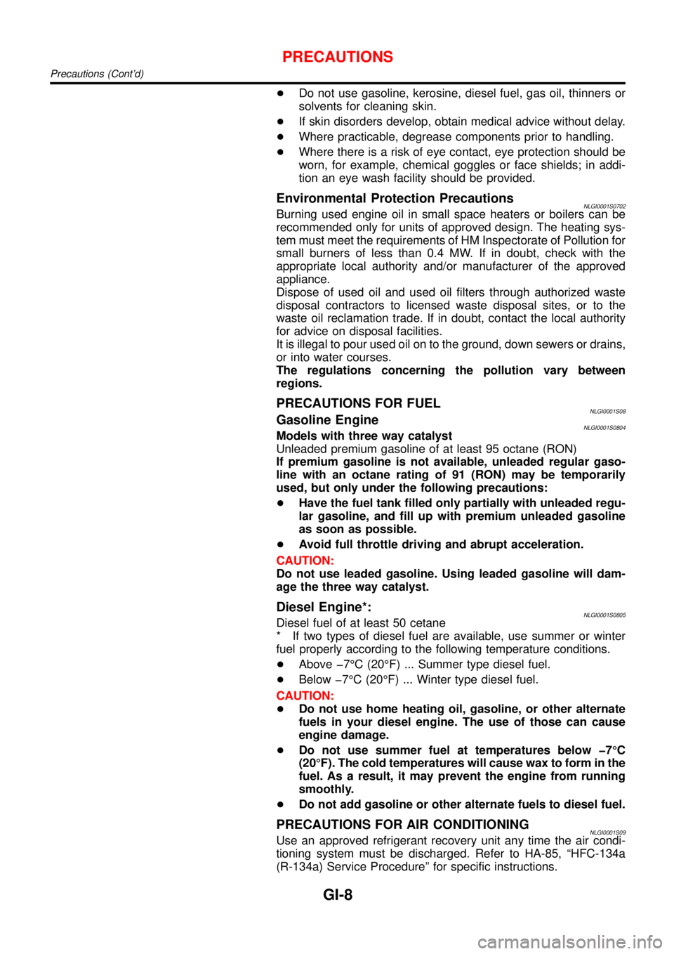
+Do not use gasoline, kerosine, diesel fuel, gas oil, thinners or
solvents for cleaning skin.
+If skin disorders develop, obtain medical advice without delay.
+Where practicable, degrease components prior to handling.
+Where there is a risk of eye contact, eye protection should be
worn, for example, chemical goggles or face shields; in addi-
tion an eye wash facility should be provided.
Environmental Protection PrecautionsNLGI0001S0702Burning used engine oil in small space heaters or boilers can be
recommended only for units of approved design. The heating sys-
tem must meet the requirements of HM Inspectorate of Pollution for
small burners of less than 0.4 MW. If in doubt, check with the
appropriate local authority and/or manufacturer of the approved
appliance.
Dispose of used oil and used oil filters through authorized waste
disposal contractors to licensed waste disposal sites, or to the
waste oil reclamation trade. If in doubt, contact the local authority
for advice on disposal facilities.
It is illegal to pour used oil on to the ground, down sewers or drains,
or into water courses.
The regulations concerning the pollution vary between
regions.
PRECAUTIONS FOR FUELNLGI0001S08Gasoline EngineNLGI0001S0804Models with three way catalyst
Unleaded premium gasoline of at least 95 octane (RON)
If premium gasoline is not available, unleaded regular gaso-
line with an octane rating of 91 (RON) may be temporarily
used, but only under the following precautions:
+Have the fuel tank filled only partially with unleaded regu-
lar gasoline, and fill up with premium unleaded gasoline
as soon as possible.
+Avoid full throttle driving and abrupt acceleration.
CAUTION:
Do not use leaded gasoline. Using leaded gasoline will dam-
age the three way catalyst.
Diesel Engine*:NLGI0001S0805Diesel fuel of at least 50 cetane
* If two types of diesel fuel are available, use summer or winter
fuel properly according to the following temperature conditions.
+Above �7°C (20°F) ... Summer type diesel fuel.
+Below �7°C (20°F) ... Winter type diesel fuel.
CAUTION:
+Do not use home heating oil, gasoline, or other alternate
fuels in your diesel engine. The use of those can cause
engine damage.
+Do not use summer fuel at temperatures below �7°C
(20°F). The cold temperatures will cause wax to form in the
fuel. As a result, it may prevent the engine from running
smoothly.
+Do not add gasoline or other alternate fuels to diesel fuel.
PRECAUTIONS FOR AIR CONDITIONINGNLGI0001S09Use an approved refrigerant recovery unit any time the air condi-
tioning system must be discharged. Refer to HA-85, “HFC-134a
(R-134a) Service Procedure” for specific instructions.
PRECAUTIONS
Precautions (Cont’d)
GI-8