Page 3014 of 3051
Be careful not to damage spacer ring during installation
SST867C
2. Tighten outer socket lock nut.
Tie-rod length“L”:
Refer to SDS, ST-28.
SST086BA
3. Measure rack stroke.
Rack stroke“S”:
Refer to SDS, ST-28.
SST967A
4. Before installing boot, coat the contact surfaces between boot
and tie-rod with grease.
SST868C
5. Install boot bands.
+Securely install boot band to boot groove and clinch the root
section of the trapezoidal area.
+Make sure that there is a clearance of 3.5 mm (0.138 in) or less
at the clinched section of the boot band. Refer to the Figure at
left.
POWER STEERING GEAR AND LINKAGE
Assembly (Cont’d)
ST-19
Page 3015 of 3051
SST090B
AdjustmentNLST00261. Check rack sliding force on vehicle as follows:
a. Install steering gear onto vehicle, but do not connect tie-rod to
knuckle arm.
b. Connect all piping and fill with steering fluid.
c. Start engine and bleed air completely.
d. Disconnect steering column lower joint from the gear.
e. Keep engine at idle and make sure steering fluid has reached
normal operating temperature.
f. Pull tie-rod slowly to move it from neutral position to±11.5 mm
(±0.453 in) at speed of 3.5 mm (0.138 in)/s. Check that rack
sliding force is within specification.
Average rack sliding force:
197 - 255 N (20.1 - 26.0 kg, 44.3 - 57.3 lb)
POWER STEERING GEAR AND LINKAGE
Adjustment
ST-20
Page 3016 of 3051
ComponentsNLST0027
NST051
NST053
InspectionNLST0028Disassemble the power steering oil pump only if the following items
are found.
+Oil leak from any point shown in the figure
+Deformed or damaged pulley
+Poor performance
POWER STEERING OIL PUMP (QG ENGINE)
Components
ST-21
Page 3017 of 3051
ComponentsNLST0044
NST052
NST053
InspectionNLST0045Disassemble the power steering oil pump only if the following items
are found.
+Oil leak from any point shown in the figure
+Deformed or damaged pulley
+Poor performance
POWER STEERING OIL PUMP (SR ENGINE)
Components
ST-22
Page 3018 of 3051
ComponentsNLST0038
SST882CA
1. Rear bracket
2. Rear body
3. Dowel pin
4. Side plate seal
5. Cam ring
6. Vane
7. Rotor
8. Side plate9. O-ring (Outer)
10. O-ring (Inner)
11. Front body
12. Drive shaft rear oil seal
13. Drive shaft front oil seal
14. Drive shaft
15. Snap ring
16. O-ring17. Outlet connector
18. Connector seal
19. Flow control valve
20. Flow control valve spring
21. Inlet connector
22. O-ring
23. Washer
SST883C
Pre-disassembly InspectionNLST0039Disassemble the power steering oil pump only if the following items
are found.
+Oil leak from any point shown in the figure
+Poor performance
POWER STEERING OIL PUMP (YD ENGINE)
Components
ST-23
Page 3019 of 3051

SST884C
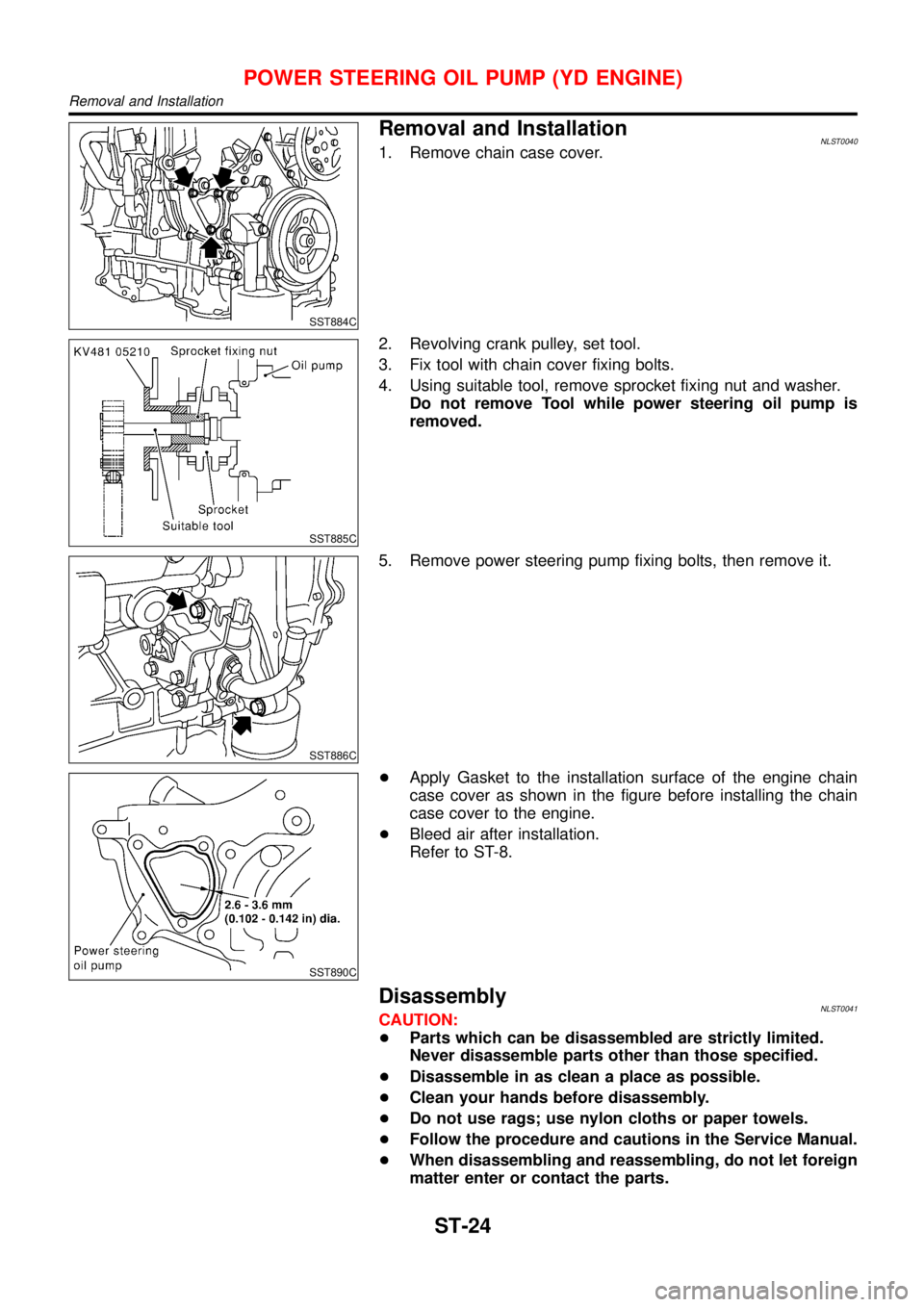
Removal and InstallationNLST00401. Remove chain case cover.
SST885C
2. Revolving crank pulley, set tool.
3. Fix tool with chain cover fixing bolts.
4. Using suitable tool, remove sprocket fixing nut and washer.
Do not remove Tool while power steering oil pump is
removed.
SST886C
5. Remove power steering pump fixing bolts, then remove it.
SST890C
+Apply Gasket to the installation surface of the engine chain
case cover as shown in the figure before installing the chain
case cover to the engine.
+Bleed air after installation.
Refer to ST-8.
DisassemblyNLST0041CAUTION:
+Parts which can be disassembled are strictly limited.
Never disassemble parts other than those specified.
+Disassemble in as clean a place as possible.
+Clean your hands before disassembly.
+Do not use rags; use nylon cloths or paper towels.
+Follow the procedure and cautions in the Service Manual.
+When disassembling and reassembling, do not let foreign
matter enter or contact the parts.
POWER STEERING OIL PUMP (YD ENGINE)
Removal and Installation
ST-24
Page 3020 of 3051
SST887C
+Remove rear bracket and rear body.
+Remove side plate seal, cam ring vane, rotor side and plate.
SST036A
+Remove inlet connector and outlet connector with spring.
Be careful not to drop the flow control valve.
Do not disassemble the flow control valve.
SST888C
+Remove oil seal
SST889C
+Remove snap ring, then draw drive shaft.
Be careful not to drop drive shaft.
InspectionNLST0042+If pulley is cracked or deformed, replace it.
+If an oil leak is found around pulley shaft oil seal, replace the
seal.
+If serration on pulley or pulley shaft is deformed or worn,
replace it.
POWER STEERING OIL PUMP (YD ENGINE)
Disassembly (Cont’d)
ST-25
Page 3021 of 3051
SST038A
AssemblyNLST0043Assemble oil pump, noting the following instructions.
+Make sure O-rings and oil seal are properly installed.
+Always install new O-rings and oil seal.
+Be careful of oil seal direction.
+Cam ring, rotor and vanes must be replaced as a set if neces-
sary.
+Coat each part with DEXRON
TMIII or equivalent when assem-
bling.
SST289A
+Pay attention to the direction of rotor.
SST843A
+When assembling vanes to rotor, rounded surfaces of vanes
must face cam ring side.
SST472C
+Insert pin 2 into pin groove 1 of front housing and front side
plate. Then install cam ring 3 as shown at left.
Cam ring:
D
1is less than D2.
POWER STEERING OIL PUMP (YD ENGINE)
Assembly
ST-26