2001 NISSAN ALMERA diagram
[x] Cancel search: diagramPage 2431 of 2898
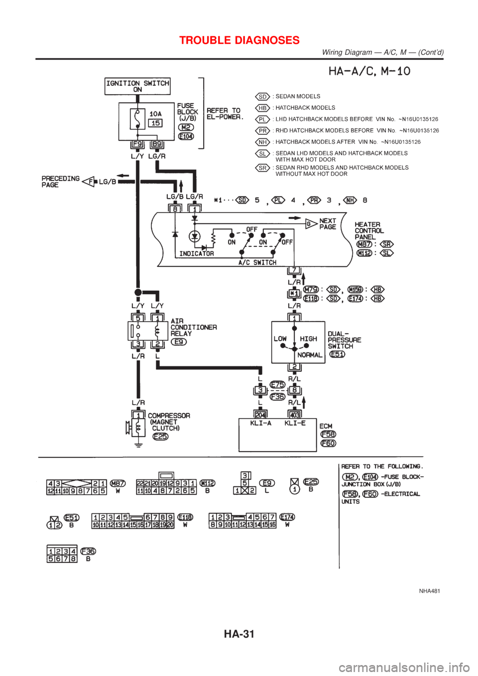
NHA481
TROUBLE DIAGNOSES
Wiring Diagram Ð A/C, M Ð (Cont'd)
HA-31
Page 2432 of 2898
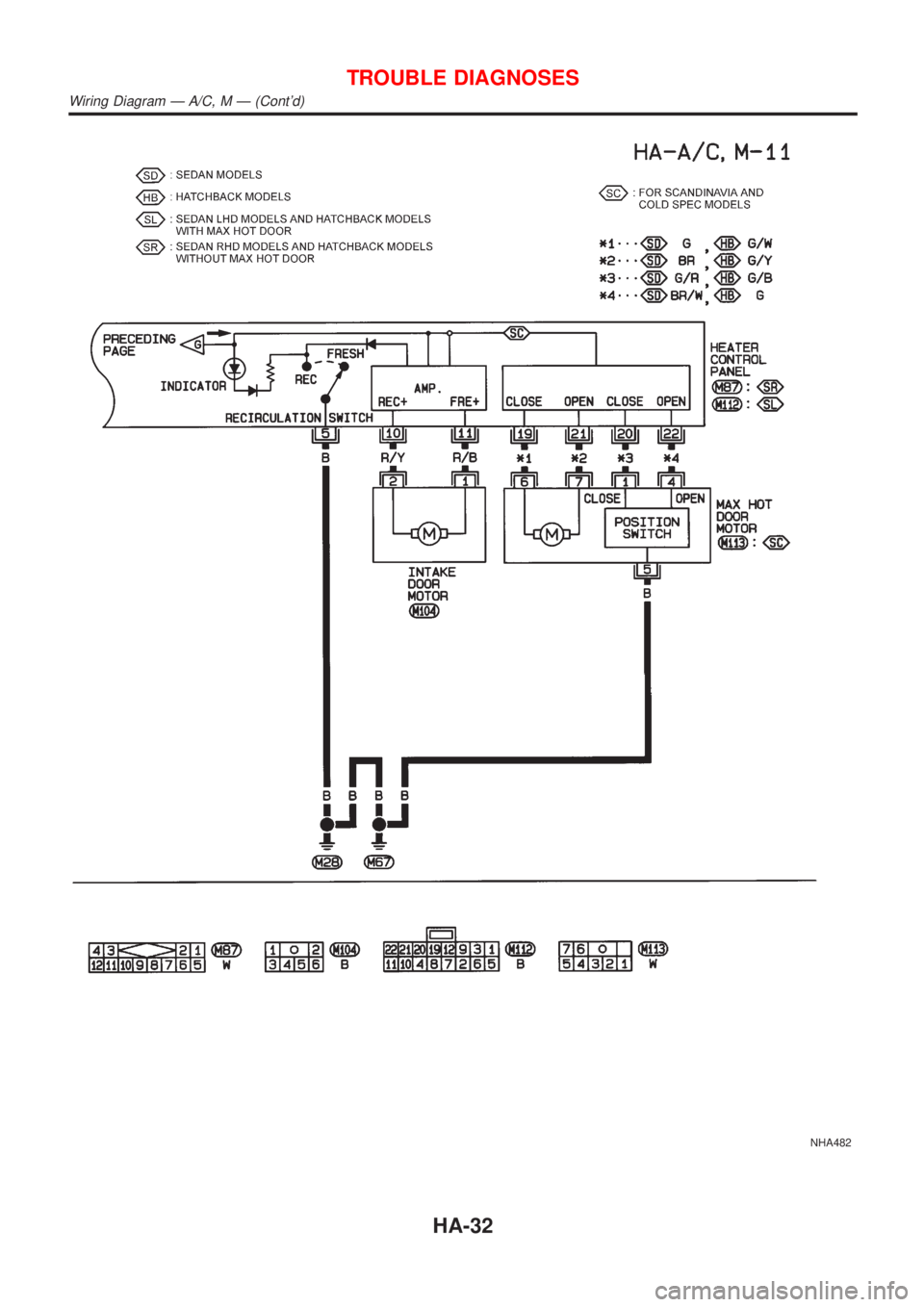
NHA482
TROUBLE DIAGNOSES
Wiring Diagram Ð A/C, M Ð (Cont'd)
HA-32
Page 2437 of 2898
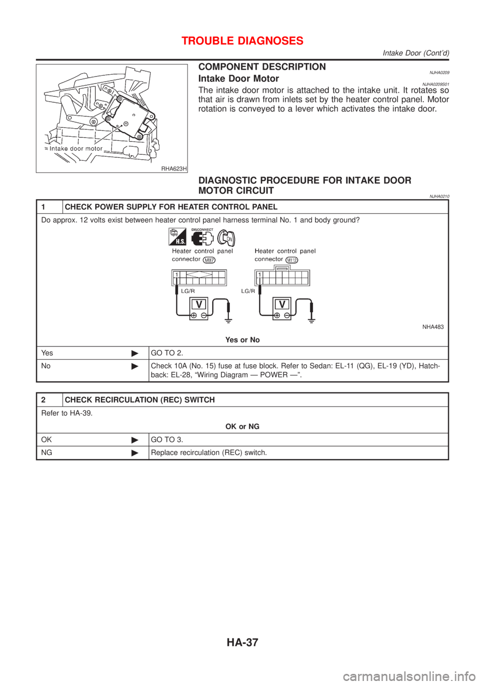
RHA623H
COMPONENT DESCRIPTIONNJHA0209Intake Door MotorNJHA0209S01The intake door motor is attached to the intake unit. It rotates so
that air is drawn from inlets set by the heater control panel. Motor
rotation is conveyed to a lever which activates the intake door.
DIAGNOSTIC PROCEDURE FOR INTAKE DOOR
MOTOR CIRCUIT
NJHA0210
1 CHECK POWER SUPPLY FOR HEATER CONTROL PANEL
Do approx. 12 volts exist between heater control panel harness terminal No. 1 and body ground?
NHA483
YesorNo
Ye s©GO TO 2.
No©Check 10A (No. 15) fuse at fuse block. Refer to Sedan: EL-11 (QG), EL-19 (YD), Hatch-
back: EL-28, ªWiring Diagram Ð POWER к.
2 CHECK RECIRCULATION (REC) SWITCH
Refer to HA-39.
OK or NG
OK©GO TO 3.
NG©Replace recirculation (REC) switch.
TROUBLE DIAGNOSES
Intake Door (Cont'd)
HA-37
Page 2449 of 2898
BLOWER MOTOR CIRCUIT=NJHA0147SYMPTOM:
+Blower motor does not rotate.
Symptom
table No.INCIDENT
1 Fan fails to rotate.
2 Fan does not rotate at 1-speed.
3 Fan does not rotate at 2-speed.
4 Fan does not rotate at 3-speed.
5 Fan does not rotate at 4-speed.
1 DIAGNOSTIC PROCEDURE
Check if blower motor rotates properly at each fan speed.
Conduct checks as per symptom table at above.
1©GO TO 2.
2, 3, 4©GO TO 8.
5©GO TO 10.
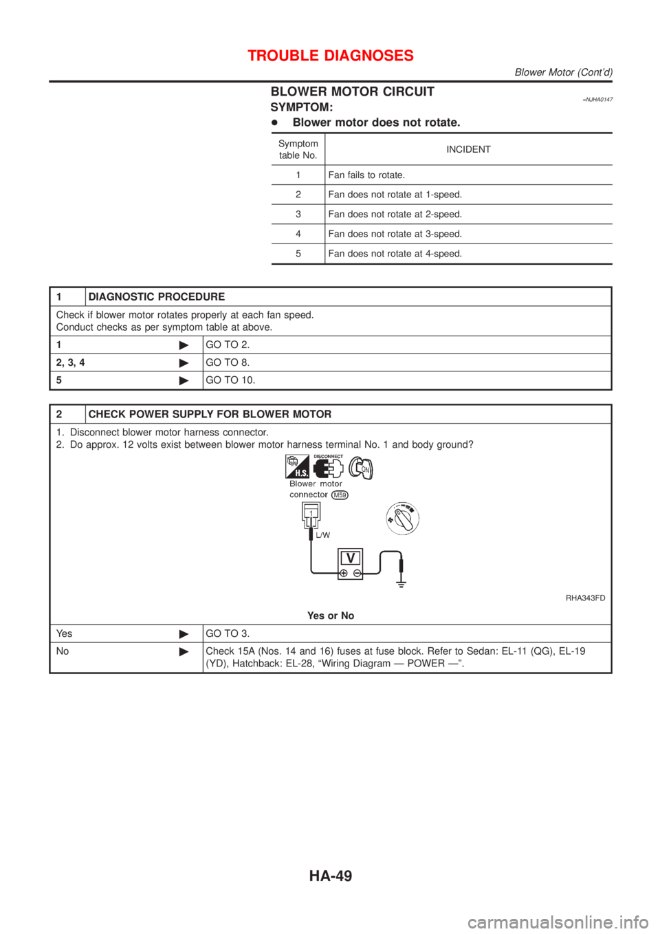
2 CHECK POWER SUPPLY FOR BLOWER MOTOR
1. Disconnect blower motor harness connector.
2. Do approx. 12 volts exist between blower motor harness terminal No. 1 and body ground?
RHA343FD
YesorNo
Ye s©GO TO 3.
No©Check 15A (Nos. 14 and 16) fuses at fuse block. Refer to Sedan: EL-11 (QG), EL-19
(YD), Hatchback: EL-28, ªWiring Diagram Ð POWER к.
TROUBLE DIAGNOSES
Blower Motor (Cont'd)
HA-49
Page 2457 of 2898
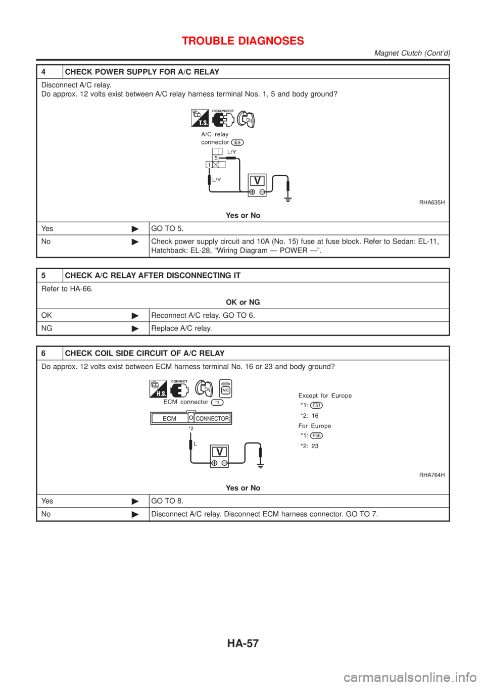
4 CHECK POWER SUPPLY FOR A/C RELAY
Disconnect A/C relay.
Do approx. 12 volts exist between A/C relay harness terminal Nos. 1, 5 and body ground?
RHA635H
YesorNo
Ye s©GO TO 5.
No©Check power supply circuit and 10A (No. 15) fuse at fuse block. Refer to Sedan: EL-11,
Hatchback: EL-28, ªWiring Diagram Ð POWER к.
5 CHECK A/C RELAY AFTER DISCONNECTING IT
Refer to HA-66.
OK or NG
OK©Reconnect A/C relay. GO TO 6.
NG©Replace A/C relay.
6 CHECK COIL SIDE CIRCUIT OF A/C RELAY
Do approx. 12 volts exist between ECM harness terminal No. 16 or 23 and body ground?
RHA764H
YesorNo
Ye s©GO TO 8.
No©Disconnect A/C relay. Disconnect ECM harness connector. GO TO 7.
TROUBLE DIAGNOSES
Magnet Clutch (Cont'd)
HA-57
Page 2462 of 2898
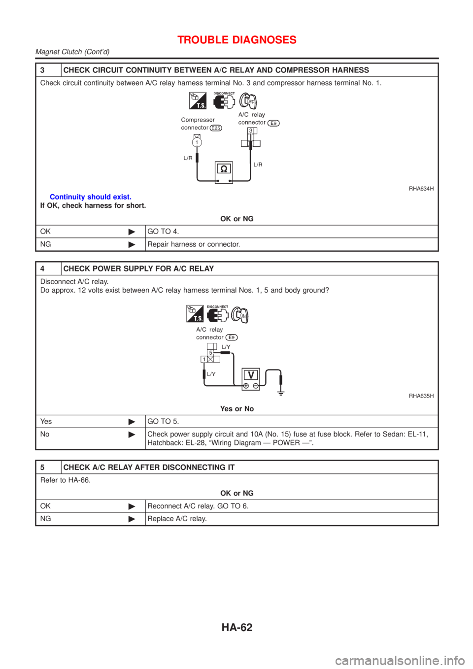
3 CHECK CIRCUIT CONTINUITY BETWEEN A/C RELAY AND COMPRESSOR HARNESS
Check circuit continuity between A/C relay harness terminal No. 3 and compressor harness terminal No. 1.
RHA634H
Continuity should exist.
If OK, check harness for short.
OK or NG
OK©GO TO 4.
NG©Repair harness or connector.
4 CHECK POWER SUPPLY FOR A/C RELAY
Disconnect A/C relay.
Do approx. 12 volts exist between A/C relay harness terminal Nos. 1, 5 and body ground?
RHA635H
YesorNo
Ye s©GO TO 5.
No©Check power supply circuit and 10A (No. 15) fuse at fuse block. Refer to Sedan: EL-11,
Hatchback: EL-28, ªWiring Diagram Ð POWER к.
5 CHECK A/C RELAY AFTER DISCONNECTING IT
Refer to HA-66.
OK or NG
OK©Reconnect A/C relay. GO TO 6.
NG©Replace A/C relay.
TROUBLE DIAGNOSES
Magnet Clutch (Cont'd)
HA-62
Page 2500 of 2898

A
A/C HFC134a (R134a) system precaution . HA-2
A/C HFC134a (R134a) system service
procedure .............................................. HA-78
A/C HFC134a (R134a) system service
tools ....................................................... HA-11
A/C HFC134a system service equip-
ment precaution ....................................... HA-6
A/C air flow ............................................... HA-20
A/C component layout .............................. HA-18
A/C compressor clutch removal and
installation .............................................. HA-83
A/C compressor precaution ........................ HA-5
A/C compressor special service tool .......... HA-9
A/C control linkage adjustment
(manual A/C) ......................................... HA-41
A/C control operation (manual A/C) .......... HA-19
A/C diagnostic work flow
(manual A/C) ........................................ HA-33
A/C harness layout (manual A/C) ............. HA-22
A/C lubricant (R134a) ............................... HA-80
A/C operational check ............................... HA-34
A/C performance chart .............................. HA-71
A/C performance test diagnoses .............. HA-69
A/C relay ................................................... HA-66
A/C service data specification .................. HA-97
A/C switch ................................................. HA-67
A/C, M - Wiring diagram ........................... HA-27
A/CCUT - Wiring diagram ....................... EC-830
A/T - Wiring diagram - AT - 1ST .............. AT-207
A/T - Wiring diagram - AT - 2ND ............. AT-214
A/T - Wiring diagram - AT - 3RD ............. AT-220
A/T - Wiring diagram - AT - 4TH .............. AT-227
A/T - Wiring diagram - AT - BA/FTS ....... AT-167,
276
A/T - Wiring diagram - AT - ENG SS ...... AT-173,
201
A/T - Wiring diagram - AT - FTS .............. AT-191
A/T - Wiring diagram - AT - LPSV ... AT-178, 241
A/T - Wiring diagram - AT - MAIN ........... AT-123
A/T - Wiring diagram - AT -
NONDTC .............................................. AT-292
A/T - Wiring diagram - AT -
OVRCSV ...................................... AT-155, 270
A/T - Wiring diagram - AT - PNP/SW ...... AT-185
A/T - Wiring diagram - AT - SSV/A .. AT-144, 248
A/T - Wiring diagram - AT - SSV/B .. AT-150, 254
A/T - Wiring diagram - AT - TCV ..... AT-161, 235
A/T - Wiring diagram - AT - TPS ..... AT-136, 261
A/T - Wiring diagram - AT - VSS/AT ....... AT-128,
197
A/T - Wiring diagram - AT -
VSSMTR ...................................... AT-132, 283
A/T IND - Wiring diagram ........................ EL-195
A/T control ............................................... EC-532
A/T diagnosis communication line .......... EC-434
A/T fluid temperature sensor ................... AT-194A/T shift lock system - Wiring
diagram ................................................ AT-344
A/T shift lock system ................................ AT-343
A/T trouble diagnoses .......................... AT-69, 74
AAC/V - Wiring diagram ................. EC-378, 513
ABS (anti-lock brake system) ................... BR-49
ABS - Wiring diagram ............................... BR-54
ABS sensor rotor ....................................... AX-24
APS - Wiring diagram ............................. EC-685
ATDIAG - Wiring diagram ............... EC-435, 533
Accelerator control system .................... FE-3, 19
Accelerator position sensor .................... EC-685
Air bag disposal ........................................ RS-40
Air bag precautions ...................................... GI-3
Air bag ....................................................... RS-20
Air bleeding (hydraulic clutch) ................... CL-10
Air bleeding for brake system ..................... BR-9
Air conditioner cut control ................. EC-35, 612
Air flow meter - See Mass air flow
sensor .......................................... EC-187, 673
Air mix door control linkage
adjustment ............................................. HA-43
Air spoiler, rear .......................................... BT-47
Alternator ................................................... SC-31
Angular tightening application .............. EM-4, 77
Antenna - See Power antenna ................ EL-282
Anti-lock brake system - Wiring
diagram .................................................. BR-54
Audio and A/C control removal and
installation - See Instrument panel ........ BT-25
Audio ........................................................ EL-258
Automatic transaxle number ...................... GI-41
Auxiliary air control (AAC) valve ..... EC-376, 511
B
Back-up lamp switch (M/T) ....................... MT-21
Back-up lamp ............................................. EL-87
Ball joint (front) .......................................... SU-13
Basic inspection ...................... EC-100, 128, 641
Battery ......................................................... SC-3
Baulk ring (M/T) ............................ MT-31, 55, 93
Blower motor ............................................. HA-54
Blower resistor .......................................... HA-54
Board-on lift ................................................ GI-44
Body alignment .......................................... BT-77
Brake booster ............................................ BR-20
Brake fluid change ...................................... BR-8
Brake fluid level and line check .................. BR-8
Brake hydraulic line .................................. BR-10
Brake master cylinder ............................... BR-14
Brake pedal ............................................... BR-12
Bulb specifications ................................... EL-574
Bumper, front .............................................. BT-7
Bumper, rear .............................................. BT-10
ALPHABETICAL INDEX
IDX-2
Page 2501 of 2898

C
CHARGE - Wiring diagram ....................... SC-27
CHIME - Wiring diagram ................. EL-199, 207
CIGAR - Wiring diagram ................. EL-236, 237
CKPS - Wiring diagram .......... EC-330, 485, 695
CMPS - Wiring diagram .......................... EC-337
CONSULT for ABS .................................... BR-65
CONSULT for engine ........................ EC-83, 632
COOL/F - Wiring diagram ............... EC-409, 730
Camshaft inspection ......................... EM-37, 123
Camshaft position sensor (CMPS) ......... EC-335
Camshaft position sensor (PHASE) ........ EC-335
Canister - See EVAP canister ................... EC-36
Charging system ....................................... SC-26
Cigarette lighter ....................................... EL-236
Circuit breaker ........................................... EL-38
Closed throttle position switch ....... EC-385, 520
Clutch cover .............................................. CL-22
Clutch disc ................................................. CL-22
Clutch master cylinder ............................... CL-11
Clutch operating cylinder ........................... CL-14
Clutch pedal .............................................. CL-10
Clutch release bearing ........................ CL-17, 20
Clutch release mechanism .................. CL-17, 20
Clutch withdrawal lever ....................... CL-17, 20
Coil spring (front) ........................................ SU-9
Coil spring (rear) ....................................... SU-21
Collision diagnosis .................................... RS-85
Combination lamp, rear, removal and
installation .............................................. BT-47
Combination meter removal and instal-
lation - See Instrument panel ................ BT-25
Combination meter .................................. EL-144
Combination switch ................................... EL-56
Compression pressure ............................. EM-83
Compressor clutch removal and
installation .............................................. HA-83
Compressor precaution ............................... HA-5
Compressor special service tool ................. HA-9
Connecting rod bearing clearance ... EM-60, 151
Connecting rod bushing clearance ... EM-61, 153
Connecting rod ................................. EM-57, 146
Console box - See Instrument panel ......... BT-25
Control lever (M/T) .................................... MT-29
Control valve (A/T) ................................... AT-388
Converter housing installation ................. AT-355
Coolant mixture ratio ................................ MA-18
Cooling circuit (engine) ....................... LC-12, 37
Cooling fan control system .................. LC-17, 43
Cooling fan control .......................... EC-406, 730
Cooling fan motor ................................... EC-417
Cooling fan relay ..................................... EC-416
Coupling sleeve (M/T) .................. MT-31, 55, 93
Crankcase emission control system -
See Positive crankcase ventilation ...... EC-39,
613
Crankcase ventilation system - See
Positive crankcase ventilation ....... EC-39, 613
Crankshaft position sensor (OBD) .. EC-328, 484Crankshaft position sensor (POS) .. EC-328, 484
Crankshaft position sensor (TDC) .......... EC-695
Crankshaft ........................................ EM-59, 148
Cylinder block ................................... EM-54, 140
Cylinder head .................................... EM-34, 119
D
DEF - Wiring diagram ...................... EL-242, 250
DTC work support ..................................... EC-92
Data link connector for Consult ........ EC-40, 632
Daytime light system ................................. EL-67
Detonation sensor - See Knock
sensor .................................................. EC-324
Diagnosis sensor unit ............................... RS-26
Diagnostic trouble code (DTC) for
OBD system .................... EC-10, 72, 596, 627
Diagnostic trouble code (DTC) inspec-
tion priority chart .................................. EC-153
Differential gear (FF A/T) ......................... AT-442
Differential gear (FF M/T) ...... MT-31, 44, 55, 93,
107
Dimensions ................................................. GI-43
Dome light - See Interior lamp ................ EL-115
Door glass ................................................. BT-17
Door lock ................................................... BT-21
Door mirror ................................................ BT-75
Door trim .................................................... BT-39
Door, front .................................................. BT-16
Door, rear ................................................... BT-16
Drive plate runout ..................................... EM-62
Drive shaft (front) ...................................... AX-10
Dropping resistor (A/T) .................... AT-182, 245
Dual pressure switch ................................ HA-13
E
ECCS-D control module ........ EC-659, 714, 792,
794, 799, 801
ECM input/output signal ................. EC-164, 659
ECTS - Wiring diagram ................... EC-203, 680
EGR control valve ................................... EC-432
EGR temperature sensor ........................ EC-418
EGR volume control valve ...................... EC-815
EGR/TS - Wiring diagram ....................... EC-421
EGRC1 - Wiring diagram ....... EC-347, 429, 494,
817
EVAP canister purge volume control
solenoid valve ........................................ EC-37
EVAP canister purge volume control
valve ............................................ EC-364, 503
EVAP canister ........................................... EC-37
Electric sunroof ........................................ EL-292
Electrical diagnoses ................................... GI-21
Electrical ignition system .......................... EC-34
Electrical load signal circuit ..................... EC-578
Electrical unit ........................................... EL-581
Electrical units location ............................ EL-517
ALPHABETICAL INDEX
IDX-3