2001 NISSAN ALMERA maintenance
[x] Cancel search: maintenancePage 2776 of 2898
![NISSAN ALMERA 2001 Service Manual SRS702
10. Check that no malfunction is detected on ªSELF-DIAG
[PAST]º.
11. Touch ªBACKº key of CONSULT-II until ªSELECT SYSTEMº
appears in order to return to User mode from Diagnosis mode.
12. NISSAN ALMERA 2001 Service Manual SRS702
10. Check that no malfunction is detected on ªSELF-DIAG
[PAST]º.
11. Touch ªBACKº key of CONSULT-II until ªSELECT SYSTEMº
appears in order to return to User mode from Diagnosis mode.
12.](/manual-img/5/57348/w960_57348-2775.png)
SRS702
10. Check that no malfunction is detected on ªSELF-DIAG
[PAST]º.
11. Touch ªBACKº key of CONSULT-II until ªSELECT SYSTEMº
appears in order to return to User mode from Diagnosis mode.
12. Turn ignition switch ªOFFº, then turn off and disconnect CON-
SULT-II.
13. Go to ªSRS Operation Checkº, page RS-59 to check SRS
operation by using ªAIR BAGº warning lamp with User mode.
DIAGNOSTIC PROCEDURE 4 (CONTINUED FROM
DIAGNOSTIC PROCEDURE 2)
NJRS0048S03Inspecting SRS malfunctioning record
1 CONSIDER POSSIBILITY OF NOT ERASING SELF-DIAGNOSTIC RESULT AFTER REPAIRING
Is it the first time for maintenance of SRS?
YesorNo
Ye s©Go to DIAGNOSTIC PROCEDURE 5 (RS-68).
No©Self-diagnostic result ªSELF-DIAG [PAST]º (previously stored in the memory) might not
be erased after repair. Go to DIAGNOSTIC PROCEDURE 3, step 8 (RS-66).
SRS834-A
SRS872
DIAGNOSTIC PROCEDURE 5NJRS0048S04Inspecting SRS intermittent malfunction by using CONSULT-II
Ð Diagnosis mode
1. Turn ignition switch ªOFFº.
2. Connect CONSULT-II to data link connector.
SUPPLEMENTAL RESTRAINT SYSTEM (SRS)
Trouble Diagnoses with CONSULT-II (Cont'd)
RS-68
Page 2789 of 2898

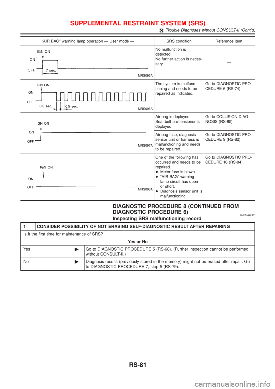
ªAIR BAGº warning lamp operation Ð User mode Ð SRS condition Reference item
MRS095A
No malfunction is
detected.
No further action is neces-
sary.Ð
MRS096A
The system is malfunc-
tioning and needs to be
repaired as indicated.Go to DIAGNOSTIC PRO-
CEDURE 6 (RS-74).
MRS097A
Air bag is deployed.
Seat belt pre-tensioner is
deployed.Go to COLLISION DIAG-
NOSIS (RS-85).
Air bag fuse, diagnosis
sensor unit or harness is
malfunctioning and needs
to be repaired.Go to DIAGNOSTIC PRO-
CEDURE 9 (RS-82).
MRS098A
One of the following has
occurred and needs to be
repaired.
+Meter fuse is blown.
+ªAIR BAGº warning
lamp circuit has open
or short.
+Diagnosis sensor unit is
malfunctioning.Go to DIAGNOSTIC PRO-
CEDURE 10 (RS-84).
DIAGNOSTIC PROCEDURE 8 (CONTINUED FROM
DIAGNOSTIC PROCEDURE 6)
NJRS0049S03Inspecting SRS malfunctioning record
1 CONSIDER POSSIBILITY OF NOT ERASING SELF-DIAGNOSTIC RESULT AFTER REPAIRING
Is it the first time for maintenance of SRS?
YesorNo
Ye s©Go to DIAGNOSTIC PROCEDURE 5 (RS-68). (Further inspection cannot be performed
without CONSULT-II.)
No©Diagnosis results (previously stored in the memory) might not be erased after repair. Go
to DIAGNOSTIC PROCEDURE 7, step 5 (RS-79).
SUPPLEMENTAL RESTRAINT SYSTEM (SRS)
Trouble Diagnoses without CONSULT-II (Cont'd)
RS-81
Page 2798 of 2898

Supplemental Restraint System (SRS) ªAIR
BAGº and ªSEAT BELT PRE-TENSIONERº
NJSC0001The Supplemental Restraint System such as ªAIR BAGº and ªSEAT BELT PRE-TENSIONERº used along with
a seat belt, helps to reduce the risk or severity of injury to the driver and front passenger for certain types of
collision. The SRS system composition which is available to NISSAN MODEL N16 is as follows (The compo-
sition varies according to the destination and optional equipment.):
+For a frontal collision
The Supplemental Restraint System consists of driver air bag module (located in the center of the steer-
ing wheel), front passenger air bag module (located on the instrument panel on passenger side), front seat
belt pre-tensioners, a diagnosis sensor unit, warning lamp, wiring harness and spiral cable.
+For a side collision
The Supplemental Restraint System consists of front side air bag module (located in the outer side of front
seat), side air bag (satellite) sensor, diagnosis sensor unit (one of components of air bags for a frontal
collision), wiring harness, warning lamp (one of components of air bags for a frontal collision).
Information necessary to service the system safely is included in theRS sectionof this Service Manual.
WARNING:
+To avoid rendering the SRS inoperative, which could increase the risk of personal injury or death
in the event of a collision which would result in air bag inflation, all maintenance should be per-
formed by an authorized NISSAN dealer.
+Improper maintenance, including incorrect removal and installation of the SRS, can lead to per-
sonal injury caused by unintentional activation of the system. For removal of Spiral Cable and Air
Bag Module, see the RS section.
+Do not use electrical test equipment on any circuit related to the SRS unless instructed to in this
Service Manual. SRS wiring harnesses can be identified by yellow harness connector.
Wiring Diagrams and Trouble DiagnosesNJSC0002When you read wiring diagrams, refer to the following:
+GI-11, ªHOW TO READ WIRING DIAGRAMSº
+EL-10, ªPOWER SUPPLY ROUTINGº for power distribution circuit
When you perform trouble diagnoses, refer to the following:
+GI-32, ªHOW TO FOLLOW TEST GROUPS IN TROUBLE DIAGNOSESº
+GI-21, ªHOW TO PERFORM EFFICIENT DIAGNOSIS FOR AN ELECTRICAL INCIDENTº
PRECAUTIONS
Supplemental Restraint System (SRS) ªAIR BAGº and ªSEAT BELT PRE-TENSIONERº
SC-2
Page 2799 of 2898

How to Handle BatteryNJSC0003CAUTION:
If it becomes necessary to start the engine with a booster
battery and jumper cables,
1) Use a 12-volt booster battery.
2) After connecting battery cables, ensure that they are
tightly clamped to battery terminals for good contact.
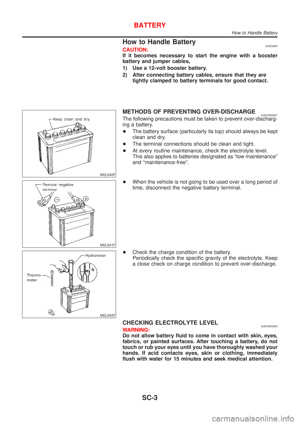
MEL040F
METHODS OF PREVENTING OVER-DISCHARGENJSC0003S01The following precautions must be taken to prevent over-discharg-
ing a battery.
+The battery surface (particularly its top) should always be kept
clean and dry.
+The terminal connections should be clean and tight.
+At every routine maintenance, check the electrolyte level.
This also applies to batteries designated as ªlow maintenanceº
and ªmaintenance-freeº.
MEL041F
+When the vehicle is not going to be used over a long period of
time, disconnect the negative battery terminal.
MEL042F
+Check the charge condition of the battery.
Periodically check the specific gravity of the electrolyte. Keep
a close check on charge condition to prevent over-discharge.
CHECKING ELECTROLYTE LEVELNJSC0003S02WARNING:
Do not allow battery fluid to come in contact with skin, eyes,
fabrics, or painted surfaces. After touching a battery, do not
touch or rub your eyes until you have thoroughly washed your
hands. If acid contacts eyes, skin or clothing, immediately
flush with water for 15 minutes and seek medical attention.
BATTERY
How to Handle Battery
SC-3
Page 2838 of 2898

Supplemental Restraint System (SRS) ªAIR
BAGº and ªSEAT BELT PRE-TENSIONERº
NJST0044The Supplemental Restraint System such as ªAIR BAGº and ªSEAT BELT PRE-TENSIONERº used along with
a seat belt, helps to reduce the risk or severity of injury to the driver and front passenger for certain types of
collision. The SRS system composition which is available to NISSAN MODEL N16 is as follows (The compo-
sition varies according to the destination and optional equipment.):
+For a frontal collision
The Supplemental Restraint System consists of driver air bag module (located in the center of the steer-
ing wheel), front passenger air bag module (located on the instrument panel on passenger side), front seat
belt pre-tensioners, a diagnosis sensor unit, warning lamp, wiring harness and spiral cable.
+For a side collision
The Supplemental Restraint System consists of front side air bag module (located in the outer side of front
seat), side air bag (satellite) sensor, diagnosis sensor unit (one of components of air bags for a frontal
collision), wiring harness, warning lamp (one of components of air bags for a frontal collision).
Information necessary to service the system safely is included in theRS sectionof this Service Manual.
WARNING:
+To avoid rendering the SRS inoperative, which could increase the risk of personal injury or death
in the event of a collision which would result in air bag inflation, all maintenance should be per-
formed by an authorized NISSAN dealer.
+Improper maintenance, including incorrect removal and installation of the SRS, can lead to per-
sonal injury caused by unintentional activation of the system. For removal of Spiral Cable and Air
Bag Module, see the RS section.
+Do not use electrical test equipment on any circuit related to the SRS unless instructed to in this
Service Manual. SRS wiring harnesses (except ªSEAT BELT PRE-TENSIONERº connector) can be
identified by yellow harness connector.
Precautions for Steering SystemNJST0003+Before disassembly, thoroughly clean the outside of the unit.
+Disassembly should be done in a clean work area. It is important to prevent the internal parts from
becoming contaminated by dirt or other foreign matter.
+Place disassembled parts in order, on a parts rack, for easier and proper assembly.
+Use nylon cloths or paper towels to clean the parts; common shop rags can leave lint that might
interfere with their operation.
+Before inspection or reassembly, carefully clean all parts with a general purpose, non-flammable
solvent.
+Before assembly, apply a coat of recommended power steering fluid* to hydraulic parts. Vaseline
may be applied to O-rings and seals. Do not use any grease.
+Replace all gaskets, seals and O-rings. Avoid damaging O-rings, seals and gaskets during instal-
lation. Perform functional tests whenever designated.
*: DEXRON
TMIII or equivalent. Refer to MA-16, ªFluids and Lubricantsº.
PRECAUTIONS
Supplemental Restraint System (SRS) ªAIR BAGº and ªSEAT BELT PRE-TENSIONERº
ST-2