Page 1519 of 2898
Wiring DiagramNJEC0747SEDAN MODELS AND HATCHBACK MODELS WITH ECM IN ENGINE COMPARTMENTNJEC0747S01
HEC839
DTC P1620 ECM RLYYD
Wiring Diagram
EC-795
Page 1520 of 2898
HATCHBACK MODELS WITH ECM IN CABINNJEC0747S02
HEC994
DTC P1620 ECM RLYYD
Wiring Diagram (Cont'd)
EC-796
Page 1521 of 2898

Diagnostic ProcedureNJEC0748
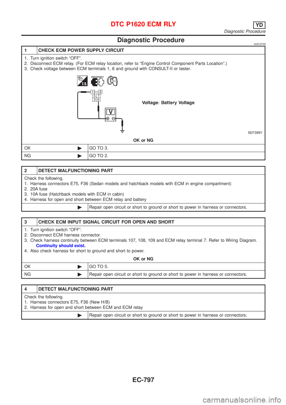
1 CHECK ECM POWER SUPPLY CIRCUIT
1. Turn ignition switch ªOFFº.
2. Disconnect ECM relay. (For ECM relay location, refer to ªEngine Control Component Parts Locationº.)
3. Check voltage between ECM terminals 1, 6 and ground with CONSULT-II or tester.
SEF399Y
OK or NG
OK©GO TO 3.
NG©GO TO 2.
2 DETECT MALFUNCTIONING PART
Check the following.
1. Harness connectors E75, F36 (Sedan models and hatchback models with ECM in engine compartment)
2. 20A fuse
3. 10A fuse (Hatchback models with ECM in cabin)
4. Harness for open and short between ECM relay and battery
©Repair open circuit or short to ground or short to power in harness or connectors.
3 CHECK ECM INPUT SIGNAL CIRCUIT FOR OPEN AND SHORT
1. Turn ignition switch ªOFFº.
2. Disconnect ECM harness connector.
3. Check harness continuity between ECM terminals 107, 108, 109 and ECM relay terminal 7. Refer to Wiring Diagram.
Continuity should exist.
4. Also check harness for short to ground and short to power.
OK or NG
OK©GO TO 5.
NG©Repair open circuit or short to ground or short to power in harness or connectors.
4 DETECT MALFUNCTIONING PART
Check the following.
1. Harness connectors E75, F36 (New H/B)
2. Harness for open and short between ECM and ECM relay
©Repair open circuit or short to ground or short to power in harness or connectors.
DTC P1620 ECM RLYYD
Diagnostic Procedure
EC-797
Page 1522 of 2898
5 CHECK ECM OUTPUT SIGNAL CIRCUIT FOR OPEN AND SHORT
1. Check harness continuity between ECM terminal 325 and ECM relay terminal 2. Refer to Wiring Diagram.
Continuity should exist.
2. Also check harness for short to ground and short to power.
OK or NG
OK©GO TO 7.
NG©GO TO 6.
6 DETECT MALFUNCTIONING PART
Check the following.
1. Harness connectors E174, M159 (New H/B)
2. Harness connectors M63, F102 (New H/B)
3. Harness for open and short between ECM and ECM relay
©Repair open circuit or short to ground or short to power in harness or connectors.
7 CHECK ECM RELAY
1. Apply 12V direct current between ECM relay terminals 1 and 2.
2. Check continuity between ECM relay terminals 3 and 5, 6 and 7.
SEF296X
OK or NG
OK©GO TO 8.
NG©Replace ECM relay.
8 CHECK INTERMITTENT INCIDENT
Refer to ªTROUBLE DIAGNOSIS FOR INTERMITTENT INCIDENTº, EC-665.
©INSPECTION END
DTC P1620 ECM RLYYD
Diagnostic Procedure (Cont'd)
EC-798
Page 1526 of 2898
2 CHECK BATTERY AND ALTERNATOR
Check that the proper type of battery and alternator is installed.
Refer to SC-38, ªBatteryº and SC-39, ªAlternatorº.
OK or NG
OK©GO TO 5.
NG©Replace with a proper one.
3 CHECK JUMPER CABLES INSTALLATION
Check that the jumper cables are connected in the correct sequence.
SEF439Z
OK or NG
OK©GO TO 4.
NG©Reconnect jumper cables properly.
4 CHECK BATTERY FOR BOOSTER
Check that the battery for the booster is a 12V battery.
OK or NG
OK©GO TO 5.
NG©Change the vehicle for booster.
5 PERFORM DTC CONFIRMATION PROCEDURE AGAIN
Perform ªDTC Confirmation Procedureº, EC-801, again.
OK or NG
OK©GO TO 6.
NG©Replace ECM.
6 CHECK ELECTRICAL PARTS DAMAGE
Check the following for damage.
+Wiring harness and harness connectors for burn
+Fuses for short
OK or NG
OK©INSPECTION END
NG©Repair or replace malfunctioning part.
DTC P1660 BATTERY VOLTAGEYD
Diagnostic Procedure (Cont'd)
EC-802
Page 1532 of 2898
Wiring DiagramNJEC0762
NEF337A
GLOW CONTROL SYSTEMYD
Wiring Diagram
EC-808
Page 1535 of 2898

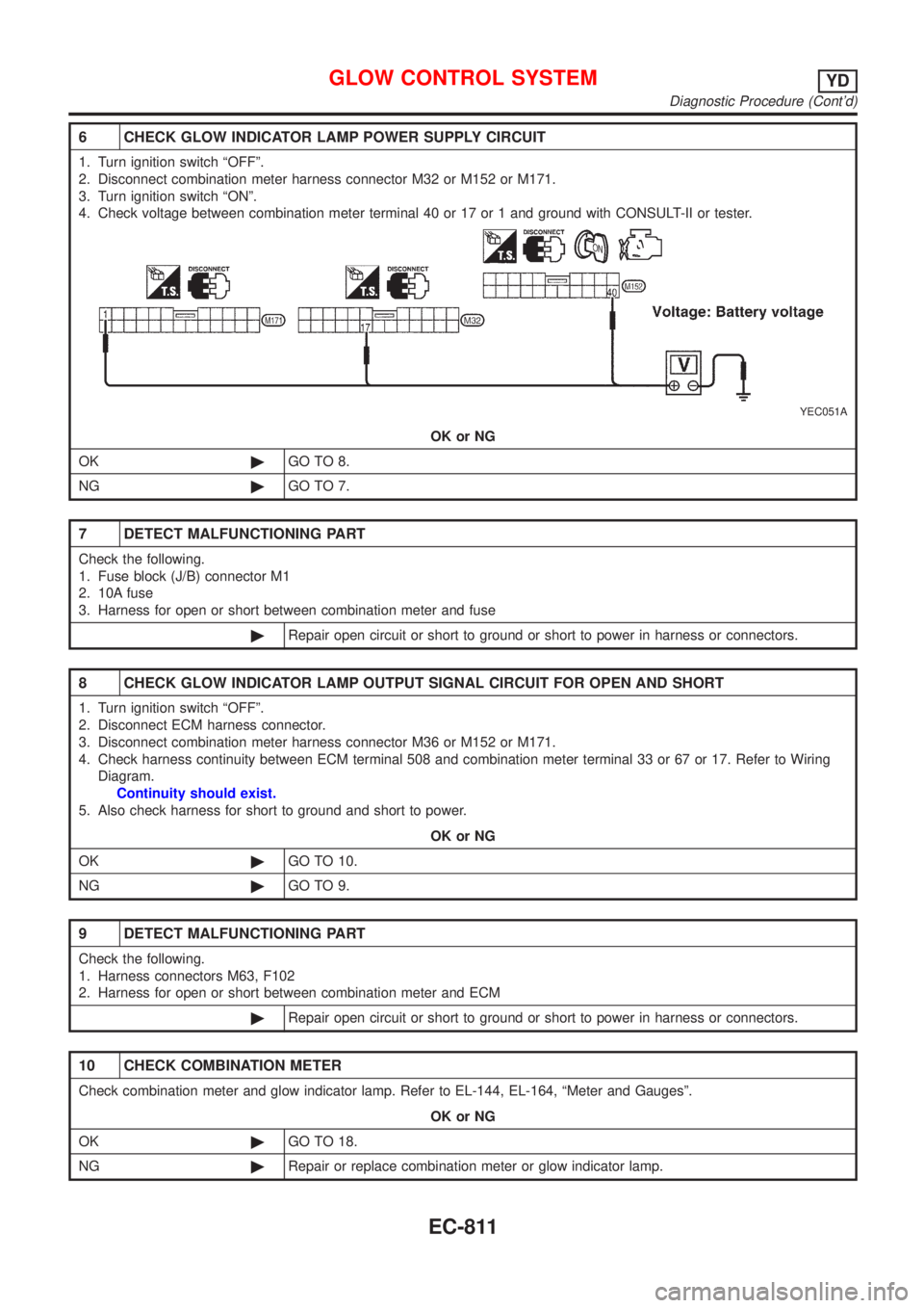
6 CHECK GLOW INDICATOR LAMP POWER SUPPLY CIRCUIT
1. Turn ignition switch ªOFFº.
2. Disconnect combination meter harness connector M32 or M152 or M171.
3. Turn ignition switch ªONº.
4. Check voltage between combination meter terminal 40 or 17 or 1 and ground with CONSULT-II or tester.
YEC051A
OK or NG
OK©GO TO 8.
NG©GO TO 7.
7 DETECT MALFUNCTIONING PART
Check the following.
1. Fuse block (J/B) connector M1
2. 10A fuse
3. Harness for open or short between combination meter and fuse
©Repair open circuit or short to ground or short to power in harness or connectors.
8 CHECK GLOW INDICATOR LAMP OUTPUT SIGNAL CIRCUIT FOR OPEN AND SHORT
1. Turn ignition switch ªOFFº.
2. Disconnect ECM harness connector.
3. Disconnect combination meter harness connector M36 or M152 or M171.
4. Check harness continuity between ECM terminal 508 and combination meter terminal 33 or 67 or 17. Refer to Wiring
Diagram.
Continuity should exist.
5. Also check harness for short to ground and short to power.
OK or NG
OK©GO TO 10.
NG©GO TO 9.
9 DETECT MALFUNCTIONING PART
Check the following.
1. Harness connectors M63, F102
2. Harness for open or short between combination meter and ECM
©Repair open circuit or short to ground or short to power in harness or connectors.
10 CHECK COMBINATION METER
Check combination meter and glow indicator lamp. Refer to EL-144, EL-164, ªMeter and Gaugesº.
OK or NG
OK©GO TO 18.
NG©Repair or replace combination meter or glow indicator lamp.
GLOW CONTROL SYSTEMYD
Diagnostic Procedure (Cont'd)
EC-811
Page 1536 of 2898

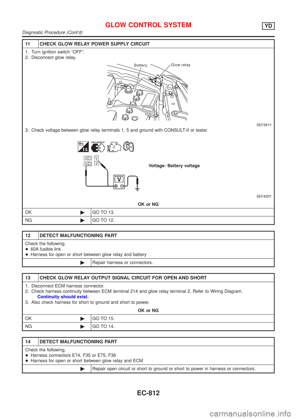
11 CHECK GLOW RELAY POWER SUPPLY CIRCUIT
1. Turn ignition switch ªOFFº.
2. Disconnect glow relay.
SEF391Y
3. Check voltage between glow relay terminals 1, 5 and ground with CONSULT-II or tester.
SEF420Y
OK or NG
OK©GO TO 13.
NG©GO TO 12.
12 DETECT MALFUNCTIONING PART
Check the following.
+60A fusible link
+Harness for open or short between glow relay and battery
©Repair harness or connectors.
13 CHECK GLOW RELAY OUTPUT SIGNAL CIRCUIT FOR OPEN AND SHORT
1. Disconnect ECM harness connector.
2. Check harness continuity between ECM terminal 214 and glow relay terminal 2. Refer to Wiring Diagram.
Continuity should exist.
3. Also check harness for short to ground and short to power.
OK or NG
OK©GO TO 15.
NG©GO TO 14.
14 DETECT MALFUNCTIONING PART
Check the following.
+Harness connectors E74, F35 or E75, F36
+Harness for open or short between glow relay and ECM
©Repair open circuit or short to ground or short to power in harness or connectors.
GLOW CONTROL SYSTEMYD
Diagnostic Procedure (Cont'd)
EC-812