2001 NISSAN ALMERA window
[x] Cancel search: windowPage 1308 of 2898
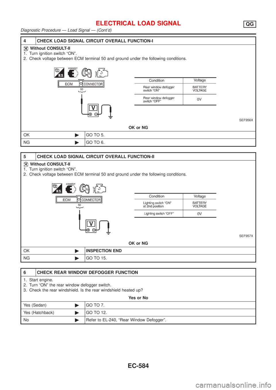
4 CHECK LOAD SIGNAL CIRCUIT OVERALL FUNCTION-I
Without CONSULT-II
1. Turn ignition switch ªONº.
2. Check voltage between ECM terminal 50 and ground under the following conditions.
SEF956X
OK or NG
OK©GO TO 5.
NG©GO TO 6.
5 CHECK LOAD SIGNAL CIRCUIT OVERALL FUNCTION-II
Without CONSULT-II
1. Turn ignition switch ªONº.
2. Check voltage between ECM terminal 50 and ground under the following conditions.
SEF957X
OK or NG
OK©INSPECTION END
NG©GO TO 15.
6 CHECK REAR WINDOW DEFOGGER FUNCTION
1. Start engine.
2. Turn ªONº the rear window defogger switch.
3. Check the rear windshield. Is the rear windshield heated up?
YesorNo
Yes (Sedan)©GO TO 7.
Yes (Hatchback)©GO TO 12.
No©Refer to EL-240, ªRear Window Defoggerº.
ELECTRICAL LOAD SIGNALQG
Diagnostic Procedure Ð Load Signal Ð (Cont'd)
EC-584
Page 1309 of 2898
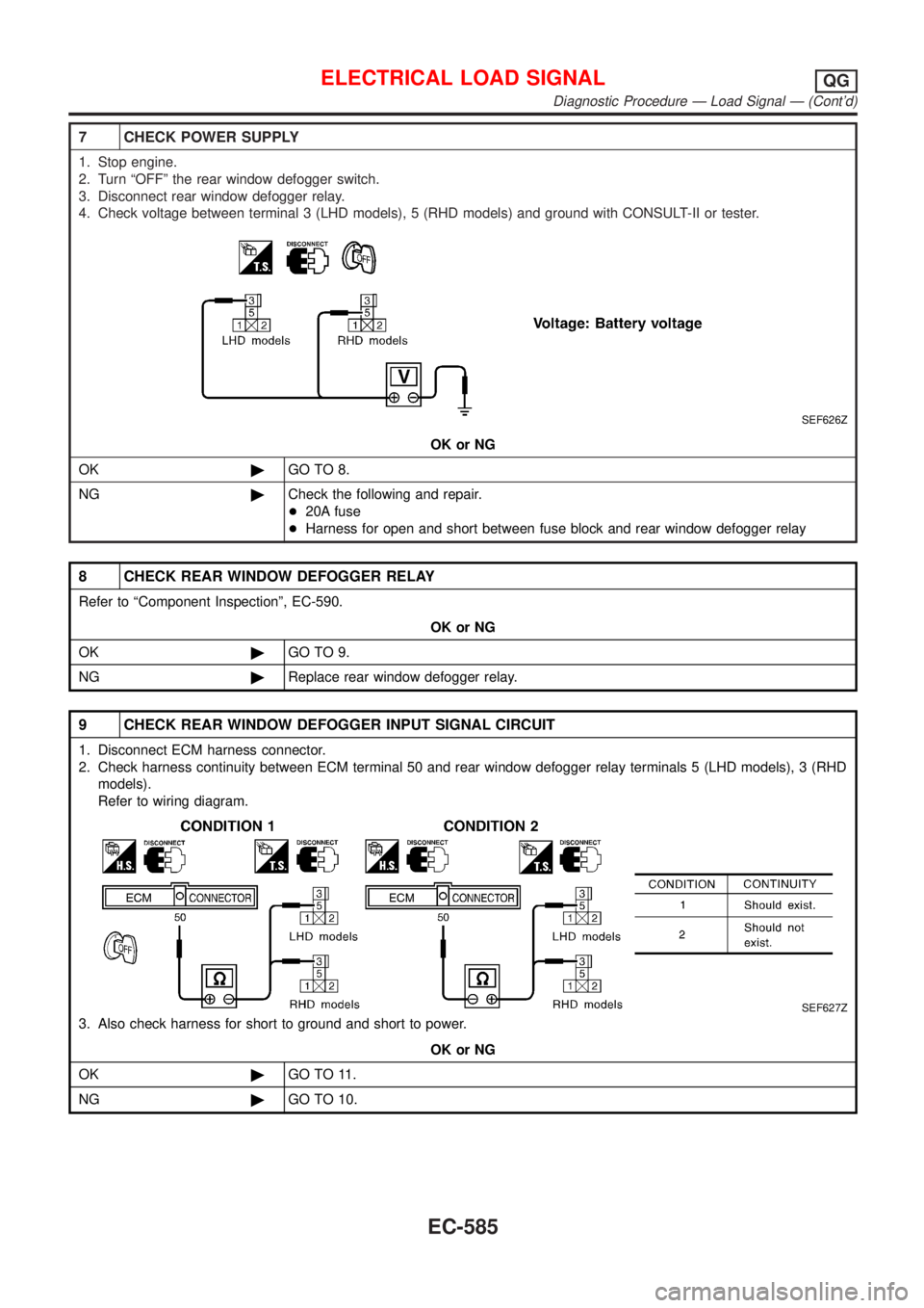
7 CHECK POWER SUPPLY
1. Stop engine.
2. Turn ªOFFº the rear window defogger switch.
3. Disconnect rear window defogger relay.
4. Check voltage between terminal 3 (LHD models), 5 (RHD models) and ground with CONSULT-II or tester.
SEF626Z
OK or NG
OK©GO TO 8.
NG©Check the following and repair.
+20A fuse
+Harness for open and short between fuse block and rear window defogger relay
8 CHECK REAR WINDOW DEFOGGER RELAY
Refer to ªComponent Inspectionº, EC-590.
OK or NG
OK©GO TO 9.
NG©Replace rear window defogger relay.
9 CHECK REAR WINDOW DEFOGGER INPUT SIGNAL CIRCUIT
1. Disconnect ECM harness connector.
2. Check harness continuity between ECM terminal 50 and rear window defogger relay terminals 5 (LHD models), 3 (RHD
models).
Refer to wiring diagram.
SEF627Z
3. Also check harness for short to ground and short to power.
OK or NG
OK©GO TO 11.
NG©GO TO 10.
ELECTRICAL LOAD SIGNALQG
Diagnostic Procedure Ð Load Signal Ð (Cont'd)
EC-585
Page 1314 of 2898
2 CHECK INPUT SIGNAL CIRCUIT
1. Stop engine.
2. Disconnect ECM harness connector.
3. Disconnect heater control panel fan switch harness connector.
4. Check harness continuity between ECM terminal 51 and heater fan switch harness connector terminal 18.
Refer to wiring diagram.
Continuity should exist.
5. Also check harness for short to ground and short to power.
OK or NG
OK©Refer to HA-48, ªBLOWER MOTORº.
NG©GO TO 3.
3 DETECT MALFUNCTIONING PART
Check the following.
+Harness connectors M94, F106 (Sedan)
+Harness connectors M73, F111 or M169, F113 (Hatchback)
+Harness for open and short between ECM and heater fan motor switch
©Repair open circuit or short to ground or short to power in harness or connectors.
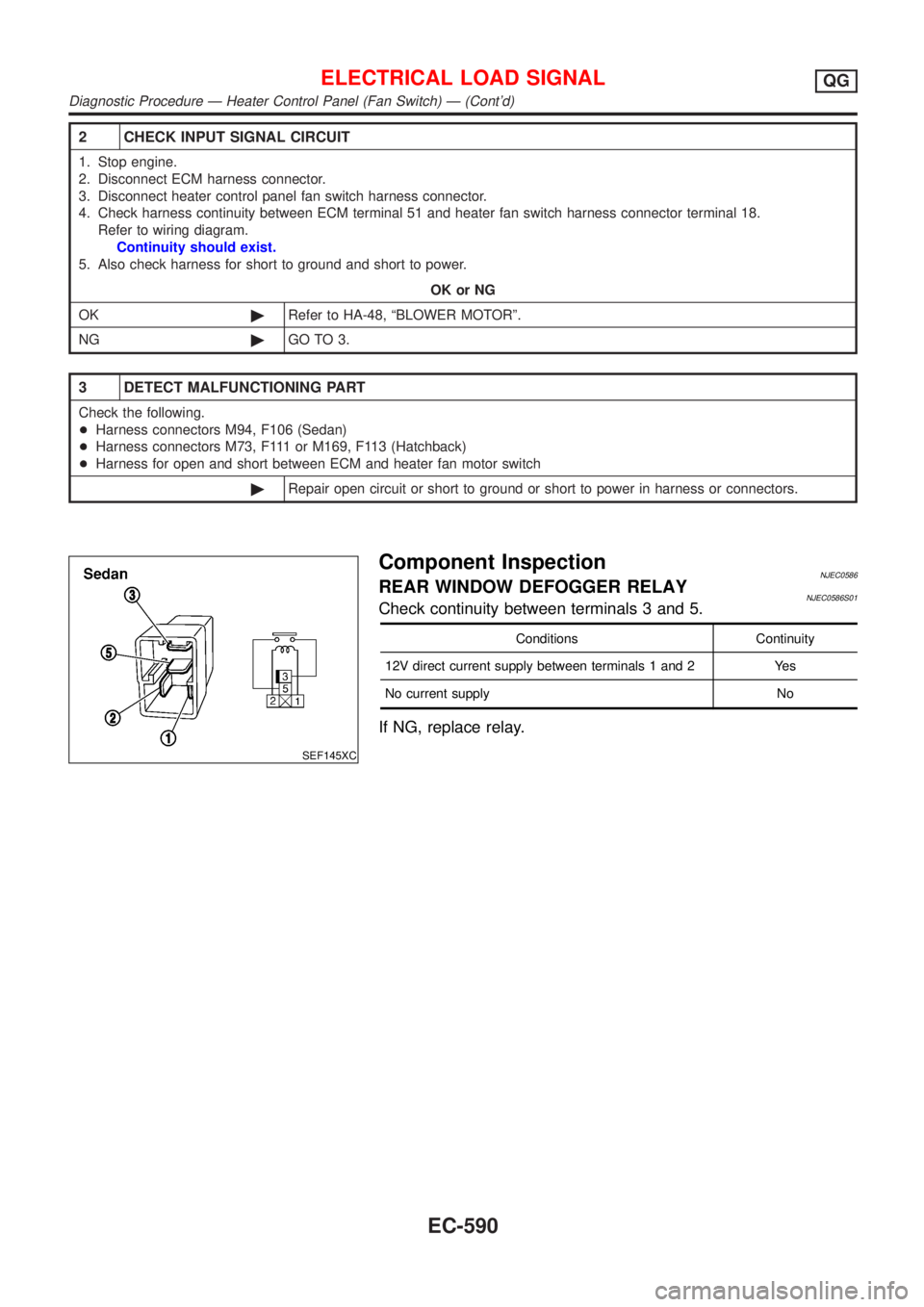
SEF145XC
Component InspectionNJEC0586REAR WINDOW DEFOGGER RELAYNJEC0586S01Check continuity between terminals 3 and 5.
Conditions Continuity
12V direct current supply between terminals 1 and 2 Yes
No current supply No
If NG, replace relay.
ELECTRICAL LOAD SIGNALQG
Diagnostic Procedure Ð Heater Control Panel (Fan Switch) Ð (Cont'd)
EC-590
Page 1317 of 2898
Fuel Pressure RegulatorNJEC0467
Fuel pressure at idling
kPa (bar, kg/cm2, psi)Vacuum hose is connected Approximately 235 (2.35, 2.4, 34)
Vacuum hose is disconnected Approximately 294 (2.94, 3.0, 43)
Idle Speed and Ignition TimingNJEC0468
Target idle speed* rpmM/T: 700±50
A/T: 800±50
Air conditioner: ON rpm825 or more
Ignition timingM/T: 8±5É BTDC
A/T: 10±5É BTDC
Throttle position sensor idle position V 0.15 - 0.85
*: Under the following conditions:
+Air conditioner switch: OFF
+Electrical load: OFF (Lights, heater fan & rear window defogger)
+Steering wheel: Kept in straight-ahead position
Mass Air Flow SensorNJEC0470
Supply voltage (Heater) VBattery voltage (11 - 14)
Supply voltage (Sensor) VApproximately 5
Output voltage V1.0 - 1.7*
Mass air flow
(Using CONSULT-II or GST) g´m/sec1.0 - 4.0 at idle*
5.0 - 10.0 at 2,500 rpm*
*: Engine is warmed up to normal operating temperature and idling under no-load.
Intake Air Temperature SensorNJEC0480
Temperature ÉC (ÉF) Resistance kW
20 (68) 2.1 - 2.9
80 (176) 0.27 - 0.38
Engine Coolant Temperature SensorNJEC0471
Temperature ÉC (ÉF) Resistance kW
20 (68) 2.1 - 2.9
50 (122) 0.68 - 1.00
90 (194) 0.236 - 0.260
Throttle Position SensorNJEC0477
Throttle valve conditions Voltage (V)
Completely closed0.15 - 0.85
Completely open3.5 - 4.7
Heated Oxygen Sensor 1 Heater (Front)NJEC0478
Resistance [at 25ÉC (77ÉF)]W2.3 - 4.3
Heated Oxygen Sensor 2 Heater (Rear)NJEC0483
Resistance [at 25ÉC (77ÉF)]W2.3 - 4.3
SERVICE DATA AND SPECIFICATIONS (SDS)QG
Fuel Pressure Regulator
EC-593
Page 1560 of 2898
Wiring Diagram - ROOM/L -/Sedan With Interior
Room Lamp Timer ................................................... 117
Trouble Diagnoses/Sedan With Interior Room
Lamp Timer .............................................................. 119
System Description/Hatchback With Interior
Room Lamp Timer ...................................................127
Wiring Diagram - ROOM/L -/Hatchback With
Interior Room Lamp Timer.......................................129
Trouble Diagnoses/Hatchback With Interior
Room Lamp Timer ...................................................131
Wiring Diagram - ROOM/L -/Sedan Without
Timer ........................................................................139
Wiring Diagram - ROOM/L -/Hatchback Without
Timer ........................................................................140
SPOT AND TRUNK ROOM LAMPS...........................141
Wiring Diagram - INT/L -/Sedan ..............................141
Wiring Diagram - INT/L -/Hatchback .......................143
METERS AND GAUGES.............................................144
Component Parts and Harness Connector
Location/Sedan ........................................................144
System Description/Sedan ......................................144
Combination Meter/Sedan With Tachometer...........146
Schematic/Sedan With Tachometer ........................147
Combination Meter/Without Tachometer .................148
Schematic/Without Tachometer ...............................149
Construction/Sedan .................................................150
Wiring Diagram - METER -/Without Tachometer ....151
Wiring Diagram - METER -/Sedan ..........................152
Meter/Gauge Operation and Odo/Trip Meter
Segment Check in Diagnosis Mode/Sedan.............153
Trouble Diagnoses/Sedan .......................................154
Electrical Components Inspection/Sedan ................162
Component Parts and Harness Connector
Location/Hatchback .................................................164
System Description/Hatchback ................................164
Combination Meter/Hatchback (Models before
VIN No. - N16U0135126) ........................................166
Combination Meter/Hatchback (Models after VIN
No. - N16U0135126) ...............................................167
Schematic/Hatchback (Models before VIN No. -
N160135126) ...........................................................168
Schematic/Hatchback (Models after VIN No. -
N16U0135126).........................................................169
Construction/Hatchback ...........................................170
Wiring Diagram - METER -/Hatchback ...................171
Combination Meter Self-Diagnosis/Hatchback ........173
Trouble Diagnoses/Hatchback.................................176
Electrical Components Inspection/Hatchback .........183
WARNING LAMPS......................................................184
Schematic/Sedan .....................................................184
Wiring Diagram - WARN -/Sedan ............................185
Schematic/Hatchback ..............................................189Wiring Diagram - WARN -/Hatchback .....................190
Electrical Components Inspection ...........................194
A/T INDICATOR...........................................................195
Wiring Diagram - AT/IND -/With Tachometer...........195
Wiring Diagram - AT/IND -/Without Tachometer......196
WARNING CHIME.......................................................197
Component Parts and Harness Connector
Location/Sedan ........................................................197
System Description/Sedan ......................................198
Wiring Diagram - CHIME -/Sedan ...........................199
Trouble Diagnoses/Sedan .......................................200
Component Parts and Harness Connector
Location/Hatchback .................................................205
System Description/Hatchback ................................206
Wiring Diagram - CHIME -/Hatchback ....................207
Trouble Diagnoses/Hatchback.................................209
FRONT WIPER AND WASHER..................................215
System Description/Sedan ......................................215
Wiring Diagram - WIPER -/Sedan ...........................217
System Description/Hatchback ................................218
Wiring Diagram - WIPER -/Hatchback ....................220
Removal and Installation .........................................222
Washer Nozzle Adjustment .....................................223
Washer Tube Layout ...............................................224
REAR WIPER AND WASHER....................................225
Wiring Diagram - WIP/R -/Sedan ............................225
Wiring Diagram - WIP/R -/Hatchback......................227
Removal and Installation .........................................229
Washer Nozzle Adjustment .....................................229
Washer Tube Layout ...............................................230
HEADLAMP WASHER................................................231
Wiring Diagram - HLC -/Sedan ...............................231
Wiring Diagram - HLC -/Hatchback .........................232
Washer Tube Layout ...............................................233
HORN...........................................................................234
Wiring Diagram - HORN -/Sedan ............................234
Wiring Diagram - HORN -/Hatchback .....................235
CIGARETTE LIGHTER................................................236
Wiring Diagram - CIGAR -/Sedan ...........................236
Wiring Diagram - CIGAR -/Hatchback.....................237
CLOCK.........................................................................238
Wiring Diagram - CLOCK -/Sedan ..........................238
Wiring Diagram - CLOCK -/Hatchback....................239
REAR WINDOW DEFOGGER.....................................240
System Description/Sedan ......................................240
Wiring Diagram - DEF -/Sedan ...............................242
Trouble Diagnoses/Sedan .......................................246
System Description/Hatchback ................................249
Wiring Diagram - DEF -/Hatchback .........................250
Trouble Diagnoses/Hatchback.................................252
Electrical Components Inspection ...........................255
Filament Check ........................................................256
CONTENTS(Cont'd)
EL-2
Page 1561 of 2898
Filament Repair .......................................................257
AUDIO..........................................................................258
System Description/Sedan ......................................258
Schematic/Sedan .....................................................260
Wiring Diagram - AUDIO -/Sedan ...........................261
System Description/Hatchback ................................269
Schematic/Hatchback ..............................................271
Wiring Diagram - AUDIO -/Hatchback .....................272
Trouble Diagnoses...................................................280
Inspection.................................................................281
AUDIO ANTENNA.......................................................282
Wiring Diagram - P/ANT - .......................................282
Location of Antenna/Power Antenna .......................283
Antenna Rod Replacement/Power Antenna ............284
Window Antenna Repair ..........................................284
Location of Antenna/Sedan With Manual Antenna..286
Antenna Rod Replacement/Sedan With Manual
Antenna....................................................................286
Location of Antenna/Hatchback ...............................287
Antenna Rod Replacement/Hatchback ...................287
HEATED SEAT............................................................288
Wiring Diagram - H/SEAT -/Sedan ..........................288
Wiring Diagram - H/SEAT -/Hatchback ...................290
POWER SUNROOF.....................................................292
Wiring Diagram - SROOF - .....................................292
Trouble Diagnoses...................................................293
DOOR MIRROR...........................................................294
Wiring Diagram - MIRROR -/Sedan ........................294
Wiring Diagram - MIRROR -/Hatchback .................295
TRUNK LID OPENER..................................................297
Wiring Diagram - TLID - ..........................................297
POWER WINDOW.......................................................298
System Description/Sedan ......................................298
Schematic/Sedan .....................................................300
Wiring Diagram - WINDOW -/Sedan .......................301
Trouble Diagnoses/Sedan .......................................305
System Description/Hatchback ................................306
Schematic/Hatchback ..............................................308
Wiring Diagram - WINDOW -/Hatchback ................309
Trouble Diagnoses/Hatchback.................................313
POWER DOOR LOCK.................................................314
System Description/Hatchback ................................314
Schematic/Hatchback ..............................................316
Wiring Diagram - D/LOCK -/Hatchback...................318
Trouble Diagnoses/Hatchback.................................325
System Description/Sedan ......................................333
Schematic/Sedan .....................................................334
Wiring Diagram - D/LOCK -/Sedan .........................335
Trouble Diagnoses/Sedan .......................................340
POWER DOOR LOCK - SUPER LOCK -...................349
System Description ..................................................349
Schematic/Sedan .....................................................351Wiring Diagram - S/LOCK -/Sedan .........................352
Trouble Diagnoses/Sedan .......................................358
Schematic/Hatchback ..............................................370
Wiring Diagram - S/LOCK -/Hatchback ...................372
Trouble Diagnoses/Hatchback.................................379
MULTI-REMOTE CONTROL SYSTEM.......................392
System Description/Sedan ......................................392
Wiring Diagram - MULTI -/Sedan ............................393
Trouble Diagnoses/Sedan .......................................395
ID Code Entry Procedure/Sedan .............................402
Remote Controller Battery Replacement/Sedan .....403
System Description/Hatchback ................................403
Wiring Diagram - MULTI -/Hatchback .....................405
Trouble Diagnoses/Hatchback.................................407
ID Code Entry Procedure/Hatchback ......................412
Remote Controller Battery
Replacement/Hatchback ..........................................413
TIME CONTROL UNIT................................................414
Description/Sedan....................................................414
Schematic/Sedan .....................................................415
Time Control Unit Inspection Table/Sedan ..............416
Description/Hatchback .............................................417
Trouble Diagnoses/Hatchback.................................418
Schematic/Hatchback ..............................................420
NATS (NISSAN ANTI-THEFT SYSTEM).....................422
Component Parts and Harness Connetor
Location ...................................................................422
System Description ..................................................423
System Composition ................................................424
Wiring Diagram - NATS -/Sedan .............................425
Wiring Diagram - NATS -/Hatchback.......................427
CONSULT-II .............................................................429
Trouble Diagnoses...................................................432
How to Replace NATS IMMU ..................................449
NAVIGATION SYSTEM...............................................450
Precautions ..............................................................450
Component Parts Location ......................................451
System Description ..................................................452
Schematic/Sedan .....................................................460
Wiring Diagram - NAVI -/Sedan ..............................461
Schematic/Hatchback ..............................................467
Wiring Diagram - NAVI -/Hatchback ........................468
Self-diagnosis Mode ................................................476
Confirmation/Adjustment Mode ...............................479
Control Panel Mode .................................................491
Guide Volume Setting ..............................................498
Anti-theft System .....................................................499
CONSULT-II .............................................................500
Trouble Diagnoses...................................................501
This Condition Is Not Abnormal...............................507
Program Loading .....................................................516
CONTENTS(Cont'd)
EL-3
Page 1613 of 2898
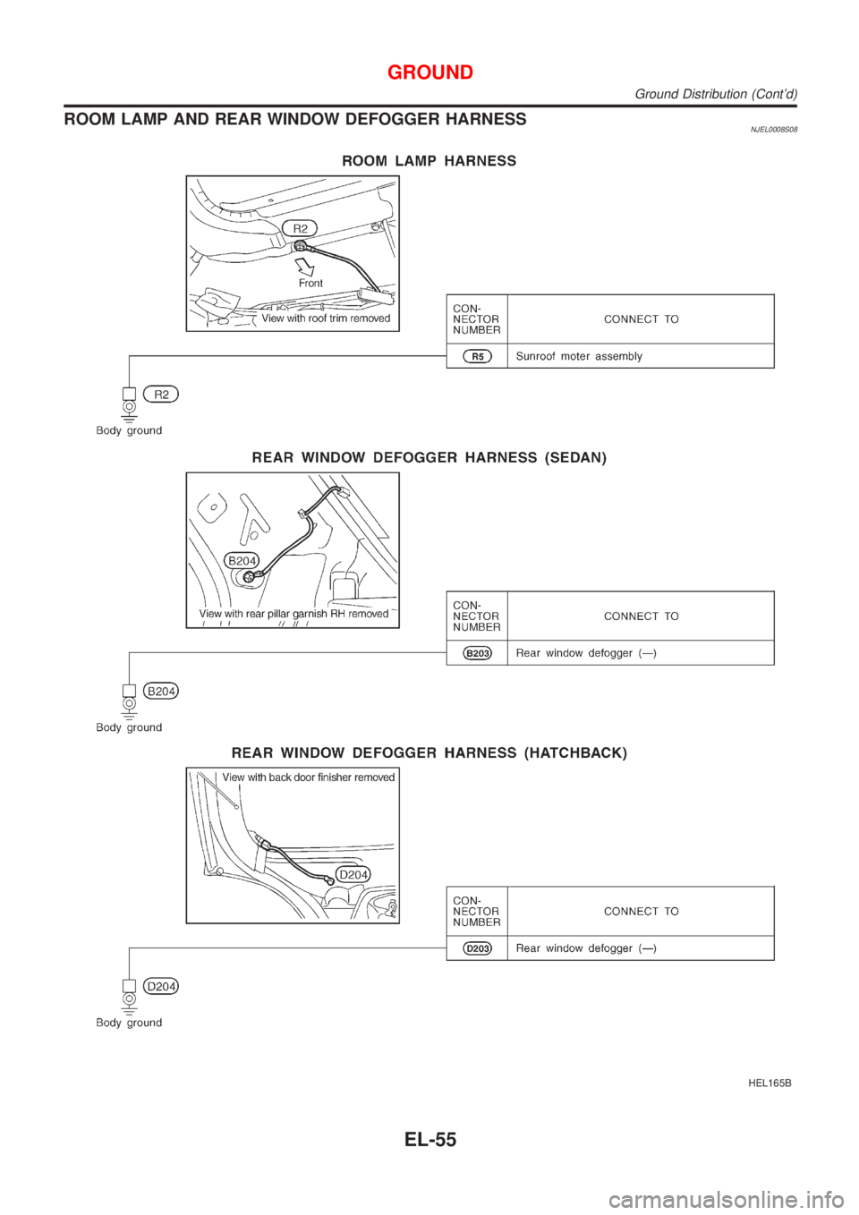
ROOM LAMP AND REAR WINDOW DEFOGGER HARNESSNJEL0008S08
HEL165B
GROUND
Ground Distribution (Cont'd)
EL-55
Page 1798 of 2898
System Description/Sedan=NJEL0378LHD MODELSNJEL0378S01The rear window defogger system is controlled by the time control unit. The rear window defogger operates
only for approximately 15 minutes.
Power is supplied at all times
+through 20A fuse [No. 7, located in the fuse block (J/B)]
+to rear window defogger relay terminal 3
+through 10A fuse [No. 13, located in the fuse block (J/B)]
+to rear window defogger relay terminal 6
+through 10A fuse [No. 12, located in the fuse block (J/B)]
+to time control unit terminal 1.
With the ignition switch in the ON or START position, power is supplied
+through 10A fuse [No. 10, located in the fuse block (J/B)]
+to the rear window defogger relay terminal 1 and
+to time control unit terminal 17.
Ground is supplied
+through body grounds M28 and M67
+to terminal 5 of the rear window defogger switch.
When the rear defogger switch is turned ON, ground is supplied
+through terminal 3 of the rear defogger switch
+to time control unit terminal 35.
Terminal 27 of time control unit then supplies ground to the rear window defogger relay terminal 2.
With power and ground supplied, the rear window defogger relay is energized.
Power is supplied
+through terminals 5 and 7 of the rear window defogger relay and
+to the rear window defogger and door mirror defogger.
The rear window defogger has an independent ground.
With power and ground supplied, the rear window defogger filaments heat and defog the rear window.
When the system is activated, the rear window defogger indicator illuminates in the rear window defogger
switch.
RHD MODELSNJEL0378S02The rear window defogger system is controlled by the time control unit. The rear window defogger operates
only for approximately 15 minutes.
Power is supplied at all times
+through 20A fuse [No. 7, located in the fuse block (J/B)]
+to rear window defogger relay terminal 5
+through 10A fuse [No. 12, located in the fuse block (J/B)]
+to time control unit terminal 1.
With the ignition switch in the ON or START position, power is supplied
+through 10A fuse [No. 10, located in the fuse block (J/B)]
+to the rear window defogger relay terminal 1 and
+to time control unit terminal 17.
Ground is supplied
+through body grounds M28 and M67
+to terminal 5 of the rear window defogger switch.
When the rear defogger switch is turned ON, ground is supplied
+through terminal 3 of the rear defogger switch
+to time control unit terminal 35.
Terminal 27 of time control unit then supplies ground to the rear window defogger relay terminal 2.
With power and ground supplied, the rear window defogger relay is energized.
Power is supplied
+through terminal 3 of the rear window defogger relay and
REAR WINDOW DEFOGGER
System Description/Sedan
EL-240