2001 NISSAN ALMERA warning light
[x] Cancel search: warning lightPage 1972 of 2898
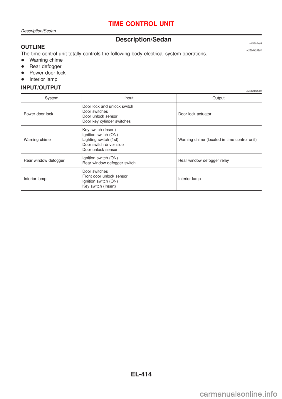
Description/Sedan=NJEL0403OUTLINENJEL0403S01The time control unit totally controls the following body electrical system operations.
+Warning chime
+Rear defogger
+Power door lock
+Interior lamp
INPUT/OUTPUTNJEL0403S02
System Input Output
Power door lockDoor lock and unlock switch
Door switches
Door unlock sensor
Door key cylinder switchesDoor lock actuator
Warning chimeKey switch (Insert)
Ignition switch (ON)
Lighting switch (1st)
Door switch driver side
Door unlock sensorWarning chime (located in time control unit)
Rear window defoggerIgnition switch (ON)
Rear window defogger switchRear window defogger relay
Interior lampDoor switches
Front door unlock sensor
Ignition switch (ON)
Key switch (Insert)Interior lamp
TIME CONTROL UNIT
Description/Sedan
EL-414
Page 1975 of 2898
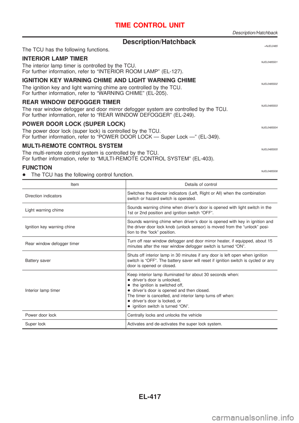
Description/Hatchback=NJEL0485The TCU has the following functions.
INTERIOR LAMP TIMERNJEL0485S01The interior lamp timer is controlled by the TCU.
For further information, refer to ªINTERIOR ROOM LAMPº (EL-127).
IGNITION KEY WARNING CHIME AND LIGHT WARNING CHIMENJEL0485S02The ignition key and light warning chime are controlled by the TCU.
For further information, refer to ªWARNING CHIMEº (EL-205).
REAR WINDOW DEFOGGER TIMERNJEL0485S03The rear window defogger and door mirror defogger system are controlled by the TCU.
For further information, refer to ªREAR WINDOW DEFOGGERº (EL-249).
POWER DOOR LOCK (SUPER LOCK)NJEL0485S04The power door lock (super lock) is controlled by the TCU.
For further information, refer to ªPOWER DOOR LOCK Ð Super Lock к (EL-349).
MULTI-REMOTE CONTROL SYSTEMNJEL0485S05The multi-remote control system is controlled by the TCU.
For further information, refer to ªMULTI-REMOTE CONTROL SYSTEMº (EL-403).
FUNCTIONNJEL0485S06+The TCU has the following control function.
Item Details of control
Direction indicatorsSwitches the director indicators (Left, Right or All) when the combination
switch or hazard switch is operated.
Light warning chimeSounds warning chime when driver's door is opened with light switch in the
1st or 2nd position and ignition switch ªOFFº.
Ignition key warning chineSounds warning chime when driver's door is opened with key in ignition and
the driver door lock knob (unlock sensor) is moved from the ªunlockº posi-
tion to the ªlockº position.
Rear window defogger timerTurn off rear window defogger and door mirror heater, if equipped, about 15
minutes after the rear window defogger switch is turned ªONº.
Battery saverShuts off interior lamp in 30 minutes if any door is left open when ignition
switch is ªOFFº. The battery saver will reset if ignition switch is cycled or any
door is opened or closed.
Interior lamp timerKeep interior lamp illuminated for about 30 seconds when:
+driver's door is unlocked,
+the ignition is switched off,
+driver's door is opened and then closed.
The timer is cancelled, and interior lamp turns off when:
+driver's door is locked, or
+ignition switch is turned ªONº.
Power door lock Centrally locks and unlocks the vehicle
Super lock Activates and de-activates the super lock system.
TIME CONTROL UNIT
Description/Hatchback
EL-417
Page 2133 of 2898
NJEL0311
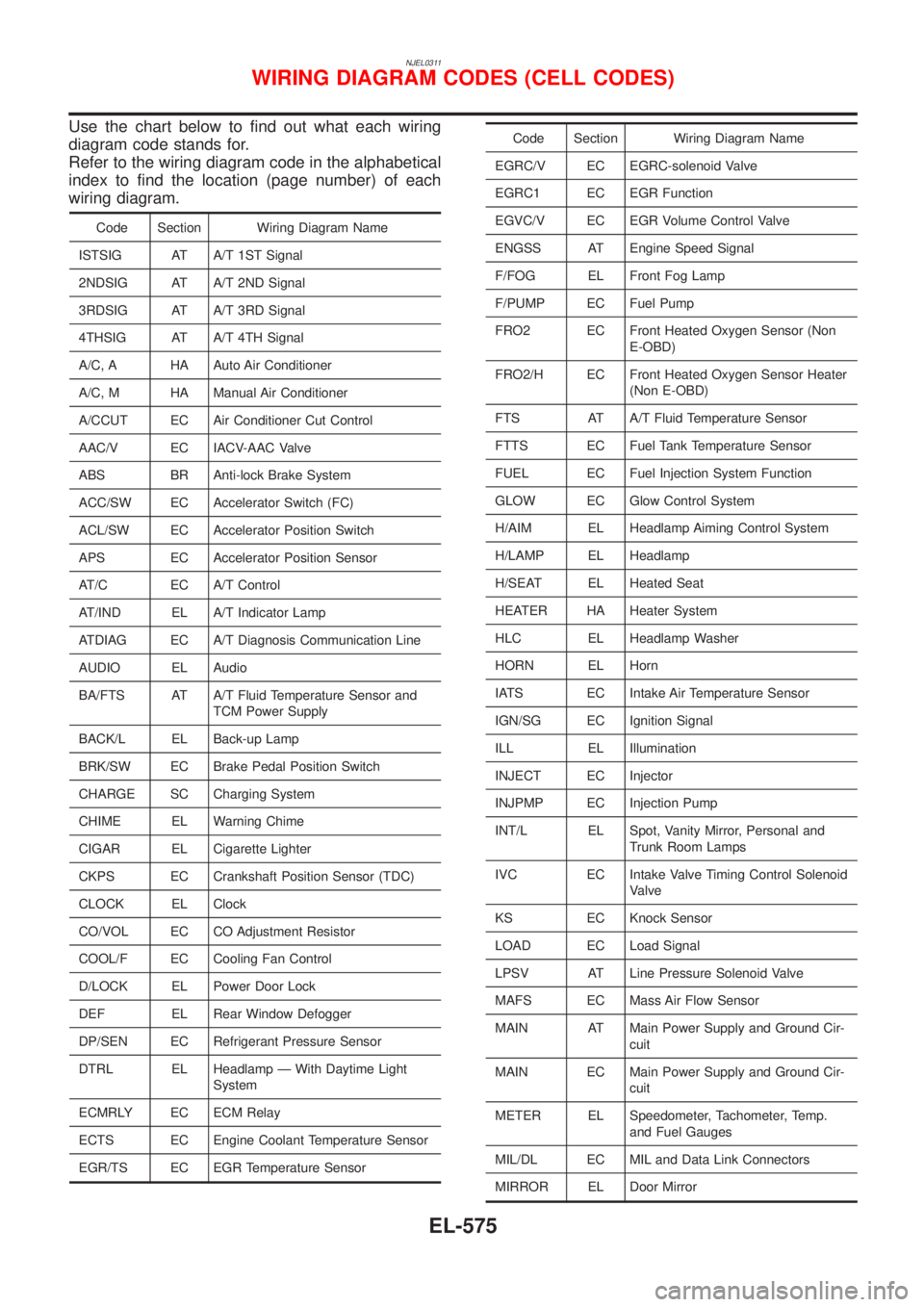
Use the chart below to find out what each wiring
diagram code stands for.
Refer to the wiring diagram code in the alphabetical
index to find the location (page number) of each
wiring diagram.
Code Section Wiring Diagram Name
ISTSIG AT A/T 1ST Signal
2NDSIG AT A/T 2ND Signal
3RDSIG AT A/T 3RD Signal
4THSIG AT A/T 4TH Signal
A/C, A HA Auto Air Conditioner
A/C, M HA Manual Air Conditioner
A/CCUT EC Air Conditioner Cut Control
AAC/V EC IACV-AAC Valve
ABS BR Anti-lock Brake System
ACC/SW EC Accelerator Switch (FC)
ACL/SW EC Accelerator Position Switch
APS EC Accelerator Position Sensor
AT/C EC A/T Control
AT/IND EL A/T Indicator Lamp
ATDIAG EC A/T Diagnosis Communication Line
AUDIO EL Audio
BA/FTS AT A/T Fluid Temperature Sensor and
TCM Power Supply
BACK/L EL Back-up Lamp
BRK/SW EC Brake Pedal Position Switch
CHARGE SC Charging System
CHIME EL Warning Chime
CIGAR EL Cigarette Lighter
CKPS EC Crankshaft Position Sensor (TDC)
CLOCK EL Clock
CO/VOL EC CO Adjustment Resistor
COOL/F EC Cooling Fan Control
D/LOCK EL Power Door Lock
DEF EL Rear Window Defogger
DP/SEN EC Refrigerant Pressure Sensor
DTRL EL Headlamp Ð With Daytime Light
System
ECMRLY EC ECM Relay
ECTS EC Engine Coolant Temperature Sensor
EGR/TS EC EGR Temperature Sensor
Code Section Wiring Diagram Name
EGRC/V EC EGRC-solenoid Valve
EGRC1 EC EGR Function
EGVC/V EC EGR Volume Control Valve
ENGSS AT Engine Speed Signal
F/FOG EL Front Fog Lamp
F/PUMP EC Fuel Pump
FRO2 EC Front Heated Oxygen Sensor (Non
E-OBD)
FRO2/H EC Front Heated Oxygen Sensor Heater
(Non E-OBD)
FTS AT A/T Fluid Temperature Sensor
FTTS EC Fuel Tank Temperature Sensor
FUEL EC Fuel Injection System Function
GLOW EC Glow Control System
H/AIM EL Headlamp Aiming Control System
H/LAMP EL Headlamp
H/SEAT EL Heated Seat
HEATER HA Heater System
HLC EL Headlamp Washer
HORN EL Horn
IATS EC Intake Air Temperature Sensor
IGN/SG EC Ignition Signal
ILL EL Illumination
INJECT EC Injector
INJPMP EC Injection Pump
INT/L EL Spot, Vanity Mirror, Personal and
Trunk Room Lamps
IVC EC Intake Valve Timing Control Solenoid
Valve
KS EC Knock Sensor
LOAD EC Load Signal
LPSV AT Line Pressure Solenoid Valve
MAFS EC Mass Air Flow Sensor
MAIN AT Main Power Supply and Ground Cir-
cuit
MAIN EC Main Power Supply and Ground Cir-
cuit
METER EL Speedometer, Tachometer, Temp.
and Fuel Gauges
MIL/DL EC MIL and Data Link Connectors
MIRROR EL Door Mirror
WIRING DIAGRAM CODES (CELL CODES)
EL-575
Page 2515 of 2898
SMA390C
5. Check oil level.
6. Start engine and check area around drain plug and oil filter for
oil leakage.
7. Run engine for a few minutes, then turn it off. After several
minutes, check oil level.
ALC094
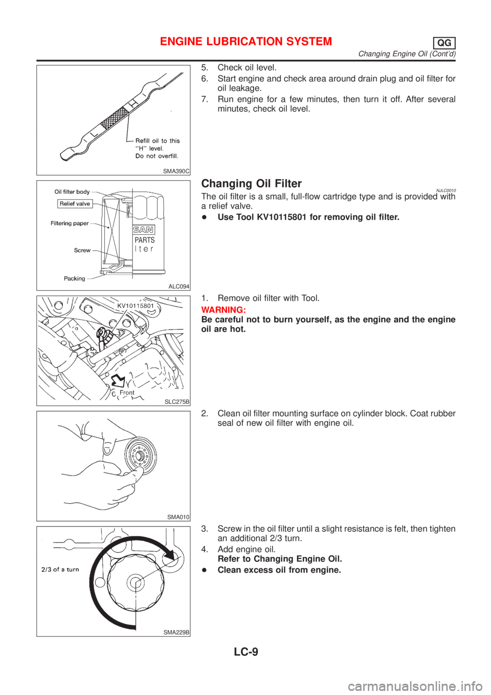
Changing Oil FilterNJLC0010The oil filter is a small, full-flow cartridge type and is provided with
a relief valve.
+Use Tool KV10115801 for removing oil filter.
SLC275B
1. Remove oil filter with Tool.
WARNING:
Be careful not to burn yourself, as the engine and the engine
oil are hot.
SMA010
2. Clean oil filter mounting surface on cylinder block. Coat rubber
seal of new oil filter with engine oil.
SMA229B
3. Screw in the oil filter until a slight resistance is felt, then tighten
an additional 2/3 turn.
4. Add engine oil.
Refer to Changing Engine Oil.
+Clean excess oil from engine.
ENGINE LUBRICATION SYSTEMQG
Changing Engine Oil (Cont'd)
LC-9
Page 2757 of 2898
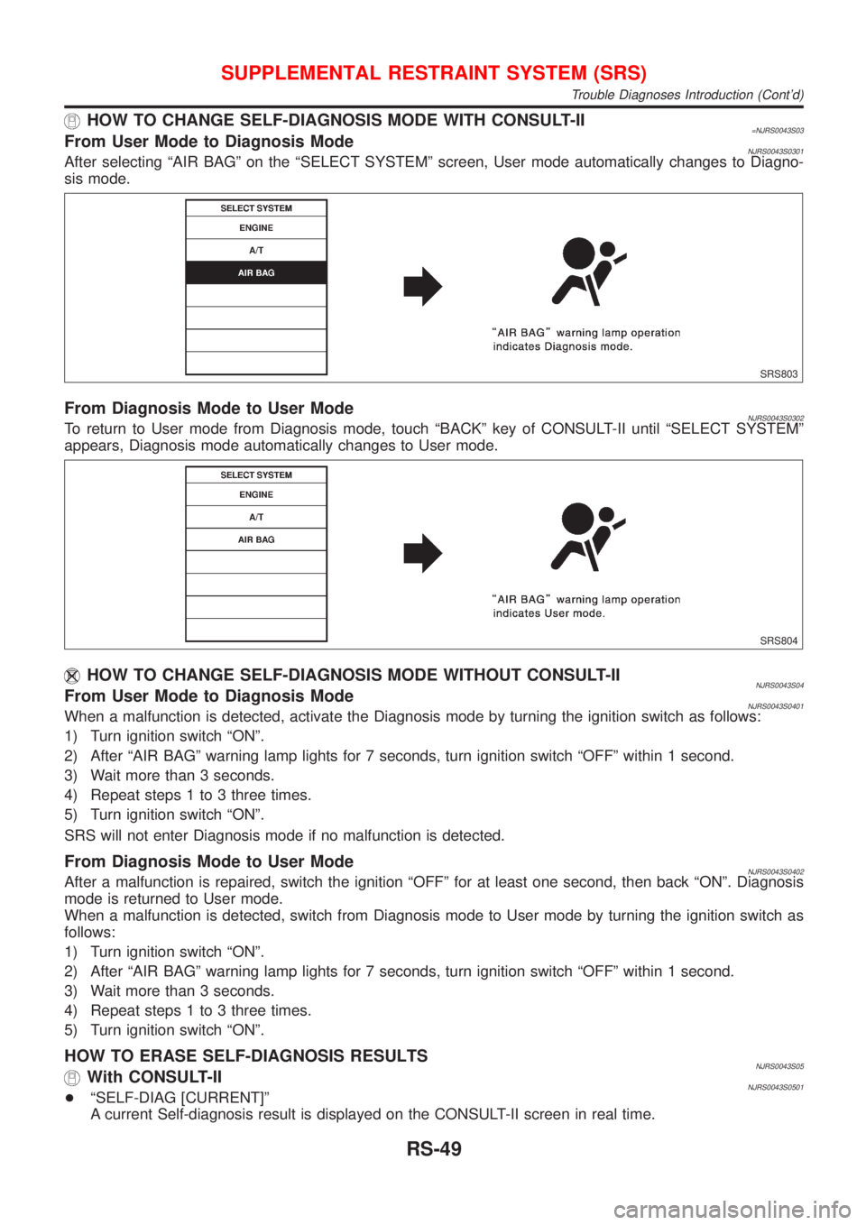
HOW TO CHANGE SELF-DIAGNOSIS MODE WITH CONSULT-II=NJRS0043S03From User Mode to Diagnosis ModeNJRS0043S0301After selecting ªAIR BAGº on the ªSELECT SYSTEMº screen, User mode automatically changes to Diagno-
sis mode.
SRS803
From Diagnosis Mode to User ModeNJRS0043S0302To return to User mode from Diagnosis mode, touch ªBACKº key of CONSULT-II until ªSELECT SYSTEMº
appears, Diagnosis mode automatically changes to User mode.
SRS804
HOW TO CHANGE SELF-DIAGNOSIS MODE WITHOUT CONSULT-IINJRS0043S04From User Mode to Diagnosis ModeNJRS0043S0401When a malfunction is detected, activate the Diagnosis mode by turning the ignition switch as follows:
1) Turn ignition switch ªONº.
2) After ªAIR BAGº warning lamp lights for 7 seconds, turn ignition switch ªOFFº within 1 second.
3) Wait more than 3 seconds.
4) Repeat steps 1 to 3 three times.
5) Turn ignition switch ªONº.
SRS will not enter Diagnosis mode if no malfunction is detected.
From Diagnosis Mode to User ModeNJRS0043S0402After a malfunction is repaired, switch the ignition ªOFFº for at least one second, then back ªONº. Diagnosis
mode is returned to User mode.
When a malfunction is detected, switch from Diagnosis mode to User mode by turning the ignition switch as
follows:
1) Turn ignition switch ªONº.
2) After ªAIR BAGº warning lamp lights for 7 seconds, turn ignition switch ªOFFº within 1 second.
3) Wait more than 3 seconds.
4) Repeat steps 1 to 3 three times.
5) Turn ignition switch ªONº.
HOW TO ERASE SELF-DIAGNOSIS RESULTSNJRS0043S05With CONSULT-IINJRS0043S0501+ªSELF-DIAG [CURRENT]º
A current Self-diagnosis result is displayed on the CONSULT-II screen in real time.
SUPPLEMENTAL RESTRAINT SYSTEM (SRS)
Trouble Diagnoses Introduction (Cont'd)
RS-49
Page 2782 of 2898
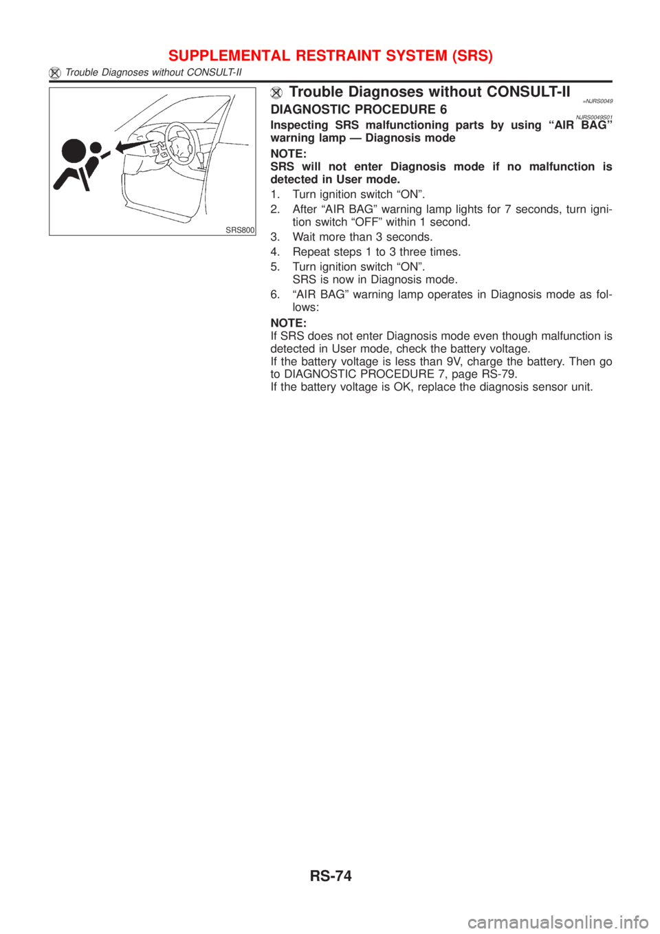
SRS800
Trouble Diagnoses without CONSULT-II=NJRS0049DIAGNOSTIC PROCEDURE 6NJRS0049S01Inspecting SRS malfunctioning parts by using ªAIR BAGº
warning lamp Ð Diagnosis mode
NOTE:
SRS will not enter Diagnosis mode if no malfunction is
detected in User mode.
1. Turn ignition switch ªONº.
2. After ªAIR BAGº warning lamp lights for 7 seconds, turn igni-
tion switch ªOFFº within 1 second.
3. Wait more than 3 seconds.
4. Repeat steps 1 to 3 three times.
5. Turn ignition switch ªONº.
SRS is now in Diagnosis mode.
6. ªAIR BAGº warning lamp operates in Diagnosis mode as fol-
lows:
NOTE:
If SRS does not enter Diagnosis mode even though malfunction is
detected in User mode, check the battery voltage.
If the battery voltage is less than 9V, charge the battery. Then go
to DIAGNOSTIC PROCEDURE 7, page RS-79.
If the battery voltage is OK, replace the diagnosis sensor unit.
SUPPLEMENTAL RESTRAINT SYSTEM (SRS)
Trouble Diagnoses without CONSULT-II
RS-74
Page 2788 of 2898
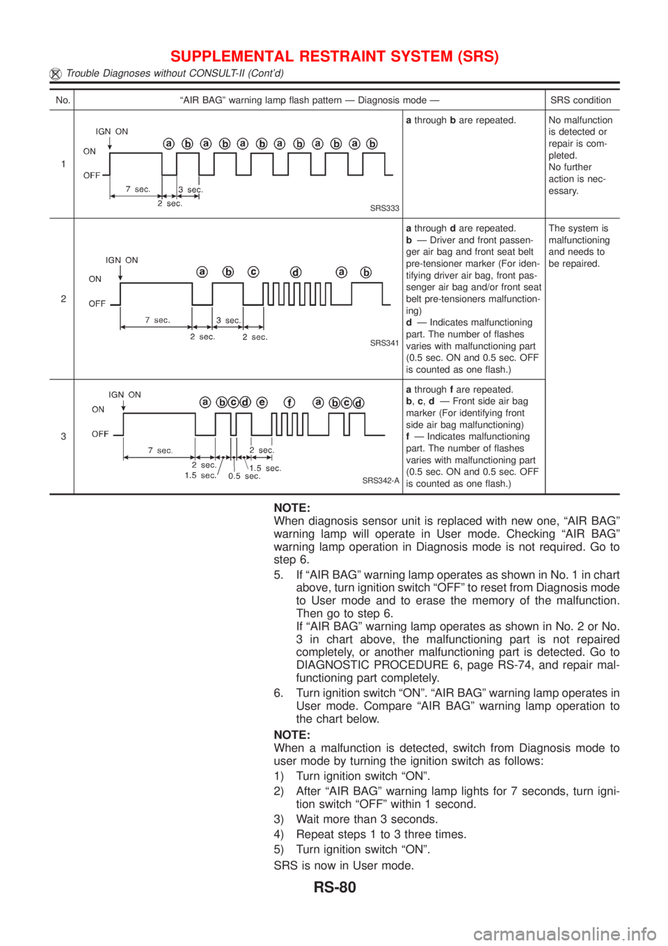
No. ªAIR BAGº warning lamp flash pattern Ð Diagnosis mode Ð SRS condition
1
SRS333
athroughbare repeated. No malfunction
is detected or
repair is com-
pleted.
No further
action is nec-
essary.
2
SRS341
athroughdare repeated.
bÐ Driver and front passen-
ger air bag and front seat belt
pre-tensioner marker (For iden-
tifying driver air bag, front pas-
senger air bag and/or front seat
belt pre-tensioners malfunction-
ing)
dÐ Indicates malfunctioning
part. The number of flashes
varies with malfunctioning part
(0.5 sec. ON and 0.5 sec. OFF
is counted as one flash.)The system is
malfunctioning
and needs to
be repaired.
3
SRS342-A
athroughfare repeated.
b,c,dÐ Front side air bag
marker (For identifying front
side air bag malfunctioning)
fÐ Indicates malfunctioning
part. The number of flashes
varies with malfunctioning part
(0.5 sec. ON and 0.5 sec. OFF
is counted as one flash.)
NOTE:
When diagnosis sensor unit is replaced with new one, ªAIR BAGº
warning lamp will operate in User mode. Checking ªAIR BAGº
warning lamp operation in Diagnosis mode is not required. Go to
step 6.
5. If ªAIR BAGº warning lamp operates as shown in No. 1 in chart
above, turn ignition switch ªOFFº to reset from Diagnosis mode
to User mode and to erase the memory of the malfunction.
Then go to step 6.
If ªAIR BAGº warning lamp operates as shown in No. 2 or No.
3 in chart above, the malfunctioning part is not repaired
completely, or another malfunctioning part is detected. Go to
DIAGNOSTIC PROCEDURE 6, page RS-74, and repair mal-
functioning part completely.
6. Turn ignition switch ªONº. ªAIR BAGº warning lamp operates in
User mode. Compare ªAIR BAGº warning lamp operation to
the chart below.
NOTE:
When a malfunction is detected, switch from Diagnosis mode to
user mode by turning the ignition switch as follows:
1) Turn ignition switch ªONº.
2) After ªAIR BAGº warning lamp lights for 7 seconds, turn igni-
tion switch ªOFFº within 1 second.
3) Wait more than 3 seconds.
4) Repeat steps 1 to 3 three times.
5) Turn ignition switch ªONº.
SRS is now in User mode.
SUPPLEMENTAL RESTRAINT SYSTEM (SRS)
Trouble Diagnoses without CONSULT-II (Cont'd)
RS-80
Page 2822 of 2898
System DescriptionNJSC0009SEDANNJSC0009S01The alternator provides DC voltage to operate the vehicle's electrical system and to keep the battery charged.
The voltage output is controlled by the IC regulator.
Power is supplied at all times to alternator terminal 4 (S) through:
+10A fuse (No. 33, located in the fuse and fusible link box).
Terminal B supplies power to charge the battery and operate the vehicle's electrical system. Output voltage
is controlled by the IC regulator at terminal 4 (S) detecting the input voltage. The charging circuit is protected
by the 80A (A/T models with QG13DE engine and M/T models with gasoline engine) or 100A (A/T models
except QG13DE engine and diesel engine models) fusible link.
The alternator is grounded to the engine block.
With the ignition switch in the ON or START position, power is supplied
+through 10A fuse [No. 30, located in the fuse block (J/B)]
+to combination meter terminal 17 (Models with tachometer) or 22 (Models without tachometer) for the
charge warning lamp.
Ground is supplied to terminal 62 (Models with tachometer) or 61 (Models without tachometer) of the combi-
nation meter through terminal 3 (L) of the alternator. With power and ground supplied, the charge warning lamp
will illuminate. When the alternator is providing sufficient voltage with the engine running, the ground is opened
and the charge warning lamp will go off.
If the charge warning lamp illuminates with the engine running, a fault is indicated.
HATCHBACKNJSC0009S02The alternator provides DC voltage to operate the vehicle's electrical system and to keep the battery charged.
The voltage output is controlled by the IC regulator.
Power is supplied at all times to alternator terminal 4 (S) through:
+10A fuse (No. 33, located in the fuse and fusible link box).
Terminal B supplies power to charge the battery and operate the vehicle's electrical system. Output voltage
is controlled by the IC regulator at terminal 4 (S) detecting the input voltage. The charging circuit is protected
by the 80A (Gasoline engine models without daytime light system) or 100A (A/T models, diesel engine mod-
els and gasoline engine models with daytime light system) fusible link.
The alternator is grounded to the engine block.
With the ignition switch in the ON or START position, power is supplied
+through 10A fuse [No. 30, located in the fuse block (J/B)]
+to combination meter terminal 40 or 1
Ground is supplied to terminal 1 or 28 of the combination meter through terminal 3 (L) of the alternator. With
power and ground supplied, the charge warning lamp will illuminate. When the alternator is providing suffi-
cient voltage with the engine running, the ground is opened and the charge warning lamp will go off.
If the charge warning lamp illuminates with the engine running, a fault is indicated.
CHARGING SYSTEM
System Description
SC-26