2001 NISSAN ALMERA battery
[x] Cancel search: batteryPage 78 of 2898

Diagnostic Worksheet=NJAT0257S0102
1.NRead the Fail-safe and listen to customer complaints. AT-9
2.NCHECK A/T FLUIDAT-80
NLeakage (Follow specified procedure)
NFluid condition
NFluid level
3.NPerform STALL TEST and LINE PRESSURE TEST. AT-80, 84
NStall test Ð Mark possible damaged components/others.
NTorque converter one-way clutch
NReverse clutch
NForward clutch
NOverrun clutch
NForward one-way clutchNLow & reverse brake
NLow one-way clutch
NEngine
NLine pressure is low
NClutches and brakes except high clutch and
brake band are OK
NLine Pressure test Ð Suspected parts:
4.NPerform all ROAD TEST and mark required procedures. AT-85
4-1. Check before engine is started. AT-87
NSELF-DIAGNOSTIC PROCEDURE Ð Mark detected items.
NPNP switch, AT-183.
NA/T fluid temperature sensor, AT-189.
NVehicle speed sensor´A/T (Revolution sensor), AT-195.
NEngine speed signal, AT-200.
NTorque converter clutch solenoid valve, AT-233.
NLine pressure solenoid valve, AT-239.
NShift solenoid valve A, AT-246.
NShift solenoid valve B, AT-252.
NThrottle position sensor, AT-258.
NOverrun clutch solenoid valve, AT-268.
NPNP, overdrive control and throttle position switches, AT-334.
NA/T fluid temperature sensor and TCM power source, AT-274.
NVehicle speed sensor´MTR, AT-281.
NControl unit (RAM), control unit (ROM), AT-286.
NControl unit (EEP ROM), AT-288.
NBattery
NOthers
4-2. Check at idleAT-89
N1. O/D OFF Indicator Lamp Does Not Come On, AT-296.
N2. Engine Cannot Be Started In ªPº And ªNº Position, AT-299.
N3. In ªPº Position, Vehicle Moves Forward Or Backward When Pushed, AT-300.
N4. In ªNº Position, Vehicle Moves, AT-301.
N5. Large Shock. ªNº®ªRº Position, AT-303.
N6. Vehicle Does Not Creep Backward In ªRº Position, AT-305.
N7. Vehicle Does Not Creep Forward In ªDº, ª2º Or ª1º Position, AT-308.
TROUBLE DIAGNOSIS Ð INTRODUCTIONEURO-OBD
Introduction (Cont'd)
AT-76
Page 79 of 2898

4. 4-3. Cruise testAT-92
AT-95
Part-1
N8. Vehicle Cannot Be Started From D
1, AT-311.
N9. A/T Does Not Shift: D
1®D2Or Does Not Kickdown: D4®D2, AT-314.
N10. A/T Does Not Shift: D
2®D3, AT-317.
N11. A/T Does Not Shift: D
3®D4, AT-320.
N12. A/T Does Not Perform Lock-up, AT-323.
N13. A/T Does Not Hold Lock-up Condition, AT-325.
N14. Lock-up Is Not Released, AT-327.
N15. Engine Speed Does Not Return To Idle (Light Braking D
4®D3), AT-328.
Part-2AT-99
N16. Vehicle Does Not Start From D
1, AT-330.
N9. A/T Does Not Shift: D
1®D2Or Does Not Kickdown: D4®D2, AT-314.
N10. A/T Does Not Shift: D
2®D3, AT-317.
N11. A/T Does Not Shift: D
3®D4, AT-320.
Part-3AT-101
N17. A/T Does Not Shift: D
4®D3When Overdrive Control Switch ªONº®ªOFFº, AT-331
N15. Engine Speed Does Not Return To Idle (Engine Brake In D
3), AT-328.
N18. A/T Does Not Shift: D
3®22, When Selector Lever ªDº®ª2º Position, AT-332.
N15. Engine Speed Does Not Return To Idle (Engine Brake In 2
2), AT-328.
N19. A/T Does Not Shift: 2
2®11, When Selector Lever ª2º®ª1º Position, AT-333.
N20. Vehicle Does Not Decelerate By Engine Brake, AT-334.
NSELF-DIAGNOSTIC PROCEDURE Ð Mark detected items.
NPNP switch, AT-183.
NA/T fluid temperature sensor, AT-189.
NVehicle speed sensor´A/T (Revolution sensor), AT-195.
NEngine speed signal, AT-200.
NTorque converter clutch solenoid valve, AT-233.
NLine pressure solenoid valve, AT-239.
NShift solenoid valve A, AT-246.
NShift solenoid valve B, AT-252.
NThrottle position sensor, AT-258.
NOverrun clutch solenoid valve, AT-268.
NPNP, overdrive control and throttle position switches, AT-334.
NA/T fluid temperature sensor and TCM power source, AT-274.
NVehicle speed sensor´MTR, AT-281.
NControl unit (RAM), control unit (ROM), AT-286.
NControl unit (EEP ROM), AT-288.
NBattery
NOthers
5.NFor self-diagnosis NG items, inspect each component. Repair or replace the damaged parts. AT-55
6.NPerform all ROAD TEST and re-mark required procedures. AT-85
7.NPerform DTC CONFIRMATION PROCEDURE for following MIL indicating items and check out NG items.
Refer to EC-60, ªEmission-related Diagnostic Informationº.EC section
NDTC (P0731) A/T 1st gear function, AT-204.
NDTC (P0732) A/T 2nd gear function, AT-211.
NDTC (P0733) A/T 3rd gear function, AT-217.
NDTC (P0734) A/T 4th gear function, AT-223.
8.NPerform the Diagnostic Procedures for all remaining items marked NG. Repair or replace the damaged
parts.
Refer to the Symptom Chart when you perform the procedures. (The chart also shows some other possible
symptoms and the component inspection orders.)AT-105
AT-118
9.NErase DTC from TCM and ECM memories. AT-52
TROUBLE DIAGNOSIS Ð INTRODUCTIONEURO-OBD
Introduction (Cont'd)
AT-77
Page 121 of 2898
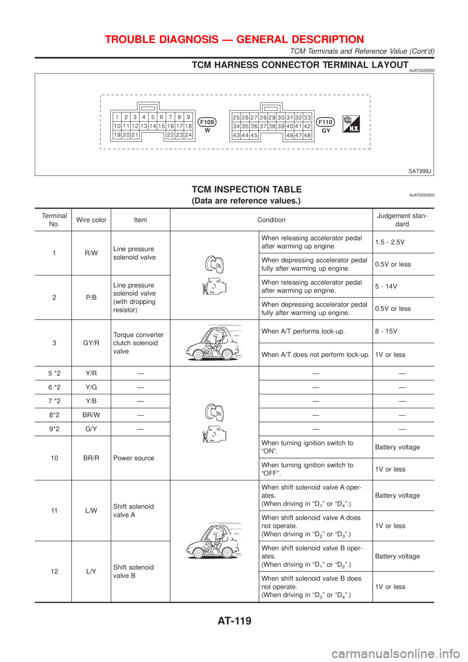
TCM HARNESS CONNECTOR TERMINAL LAYOUTNJAT0030S02
SAT999J
TCM INSPECTION TABLENJAT0030S03(Data are reference values.)
Terminal
No.Wire color Item ConditionJudgement stan-
dard
1 R/WLine pressure
solenoid valve
When releasing accelerator pedal
after warming up engine.1.5 - 2.5V
When depressing accelerator pedal
fully after warming up engine.0.5V or less
2 P/BLine pressure
solenoid valve
(with dropping
resistor)When releasing accelerator pedal
after warming up engine.5 - 14V
When depressing accelerator pedal
fully after warming up engine.0.5V or less
3 GY/RTorque converter
clutch solenoid
valve
When A/T performs lock-up. 8 - 15V
When A/T does not perform lock-up. 1V or less
5 *2 Y/R Ð
ÐÐ
6 *2 Y/G Ð Ð Ð
7 *2 Y/B Ð Ð Ð
8*2 BR/W Ð Ð Ð
9*2 G/Y Ð Ð Ð
10 BR/R Power sourceWhen turning ignition switch to
ªONº.Battery voltage
When turning ignition switch to
ªOFFº.1V or less
11 L/WShift solenoid
valve A
When shift solenoid valve A oper-
ates.
(When driving in ªD
1ºorªD4º.)Battery voltage
When shift solenoid valve A does
not operate.
(When driving in ªD
2ºorªD3º.)1V or less
12 L/YShift solenoid
valve BWhen shift solenoid valve B oper-
ates.
(When driving in ªD
1ºorªD2º.)Battery voltage
When shift solenoid valve B does
not operate.
(When driving in ªD
3ºorªD4º.)1V or less
TROUBLE DIAGNOSIS Ð GENERAL DESCRIPTION
TCM Terminals and Reference Value (Cont'd)
AT-119
Page 122 of 2898
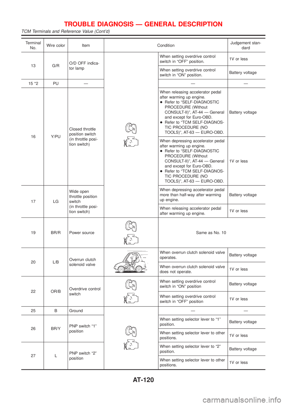
Terminal
No.Wire color Item ConditionJudgement stan-
dard
13 G/RO/D OFF indica-
tor lamp
When setting overdrive control
switch in ªOFFº position.1V or less
When setting overdrive control
switch in ªONº position.Battery voltage
15 *2 PU Ð Ð Ð
16 Y/PUClosed throttle
position switch
(in throttle posi-
tion switch)When releasing accelerator pedal
after warming up engine.
+Refer to ªSELF-DIAGNOSTIC
PROCEDURE (Without
CONSULT-II)º, AT-44 Ð General
and except for Euro-OBD.
+Refer to ªTCM SELF-DIAGNOS-
TIC PROCEDURE (NO
TOOLS)º, AT-63 Ð EURO-OBD.Battery voltage
When depressing accelerator pedal
after warming up engine.
+Refer to ªSELF-DIAGNOSTIC
PROCEDURE (Without
CONSULT-II)º, AT-44 Ð General
and except for Euro-OBD.
+Refer to ªTCM SELF-DIAGNOS-
TIC PROCEDURE (NO
TOOLS)º, AT-63 Ð EURO-OBD.1V or less
17 LGWide open
throttle position
switch
(in throttle posi-
tion switch)When depressing accelerator pedal
more than half-way after warming
up engine.Battery voltage
When releasing accelerator pedal
after warming up engine.1V or less
19 BR/R Power source
Same as No. 10
20 L/BOverrun clutch
solenoid valve
When overrun clutch solenoid valve
operates.Battery voltage
When overrun clutch solenoid valve
does not operate.1V or less
22 OR/BOverdrive control
switch
When setting overdrive control
switch in ªONº positionBattery voltage
When setting overdrive control
switch in ªOFFº position1V or less
25 B Ground
ÐÐ
26 BR/YPNP switch ª1º
positionWhen setting selector lever to ª1º
position.Battery voltage
When setting selector lever to other
positions.1V or less
27 LPNP switch ª2º
positionWhen setting selector lever to ª2º
position.Battery voltage
When setting selector lever to other
positions.1V or less
TROUBLE DIAGNOSIS Ð GENERAL DESCRIPTION
TCM Terminals and Reference Value (Cont'd)
AT-120
Page 123 of 2898
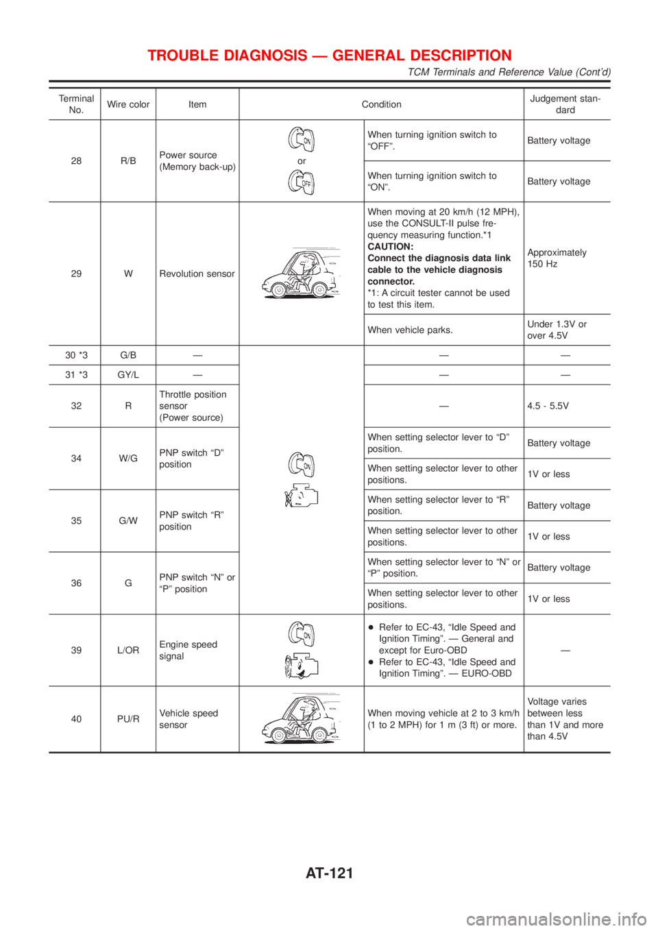
Terminal
No.Wire color Item ConditionJudgement stan-
dard
28 R/BPower source
(Memory back-up)
or
When turning ignition switch to
ªOFFº.Battery voltage
When turning ignition switch to
ªONº.Battery voltage
29 W Revolution sensor
When moving at 20 km/h (12 MPH),
use the CONSULT-II pulse fre-
quency measuring function.*1
CAUTION:
Connect the diagnosis data link
cable to the vehicle diagnosis
connector.
*1: A circuit tester cannot be used
to test this item.Approximately
150 Hz
When vehicle parks.Under 1.3V or
over 4.5V
30 *3 G/B Ð
ÐÐ
31 *3 GY/L Ð Ð Ð
32 RThrottle position
sensor
(Power source)Ð 4.5 - 5.5V
34 W/GPNP switch ªDº
positionWhen setting selector lever to ªDº
position.Battery voltage
When setting selector lever to other
positions.1V or less
35 G/WPNP switch ªRº
positionWhen setting selector lever to ªRº
position.Battery voltage
When setting selector lever to other
positions.1V or less
36 GPNP switch ªNº or
ªPº positionWhen setting selector lever to ªNº or
ªPº position.Battery voltage
When setting selector lever to other
positions.1V or less
39 L/OREngine speed
signal
+Refer to EC-43, ªIdle Speed and
Ignition Timingº. Ð General and
except for Euro-OBD
+Refer to EC-43, ªIdle Speed and
Ignition Timingº. Ð EURO-OBDÐ
40 PU/RVehicle speed
sensor
When moving vehicle at 2 to 3 km/h
(1 to 2 MPH) for1m(3ft)ormore.Voltage varies
between less
than 1V and more
than 4.5V
TROUBLE DIAGNOSIS Ð GENERAL DESCRIPTION
TCM Terminals and Reference Value (Cont'd)
AT-121
Page 124 of 2898
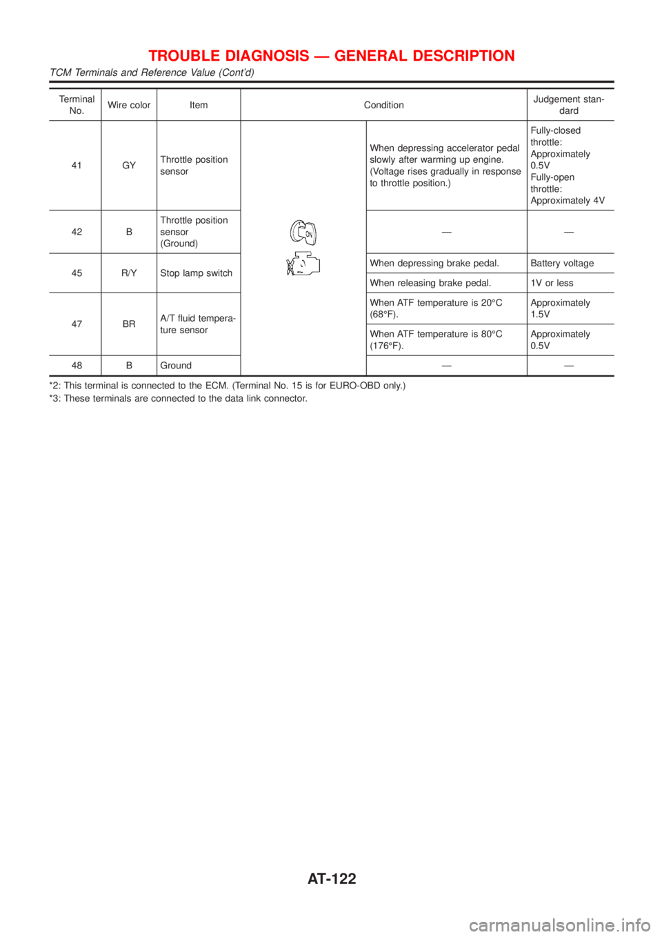
Terminal
No.Wire color Item ConditionJudgement stan-
dard
41 GYThrottle position
sensor
When depressing accelerator pedal
slowly after warming up engine.
(Voltage rises gradually in response
to throttle position.)Fully-closed
throttle:
Approximately
0.5V
Fully-open
throttle:
Approximately 4V
42 BThrottle position
sensor
(Ground)ÐÐ
45 R/Y Stop lamp switchWhen depressing brake pedal. Battery voltage
When releasing brake pedal. 1V or less
47 BRA/T fluid tempera-
ture sensorWhen ATF temperature is 20ÉC
(68ÉF).Approximately
1.5V
When ATF temperature is 80ÉC
(176ÉF).Approximately
0.5V
48 B Ground Ð Ð
*2: This terminal is connected to the ECM. (Terminal No. 15 is for EURO-OBD only.)
*3: These terminals are connected to the data link connector.
TROUBLE DIAGNOSIS Ð GENERAL DESCRIPTION
TCM Terminals and Reference Value (Cont'd)
AT-122
Page 126 of 2898
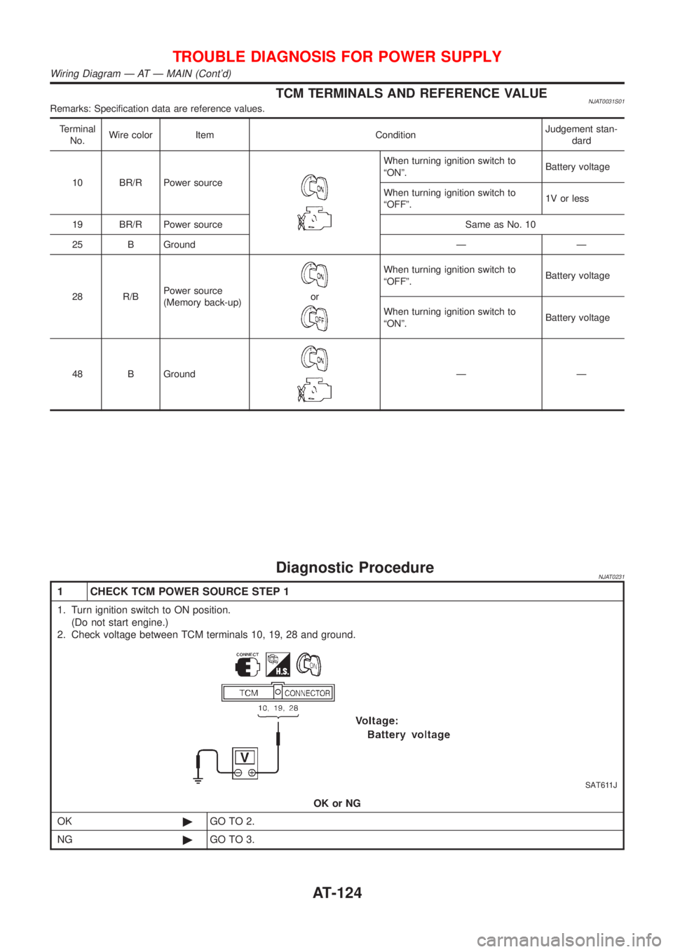
TCM TERMINALS AND REFERENCE VALUENJAT0031S01Remarks: Specification data are reference values.
Terminal
No.Wire color Item ConditionJudgement stan-
dard
10 BR/R Power source
When turning ignition switch to
ªONº.Battery voltage
When turning ignition switch to
ªOFFº.1V or less
19 BR/R Power source Same as No. 10
25 B Ground Ð Ð
28 R/BPower source
(Memory back-up)
or
When turning ignition switch to
ªOFFº.Battery voltage
When turning ignition switch to
ªONº.Battery voltage
48 B Ground
ÐÐ
Diagnostic ProcedureNJAT0231
1 CHECK TCM POWER SOURCE STEP 1
1. Turn ignition switch to ON position.
(Do not start engine.)
2. Check voltage between TCM terminals 10, 19, 28 and ground.
SAT611J
OK or NG
OK©GO TO 2.
NG©GO TO 3.
TROUBLE DIAGNOSIS FOR POWER SUPPLY
Wiring Diagram Ð AT Ð MAIN (Cont'd)
AT-124
Page 136 of 2898
SAT004K
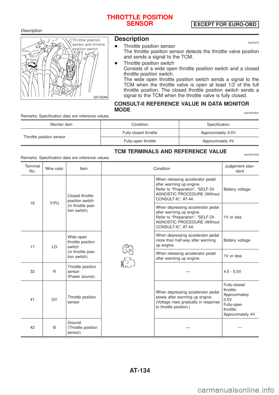
DescriptionNJAT0070+Throttle position sensor
The throttle position sensor detects the throttle valve position
and sends a signal to the TCM.
+Throttle position switch
Consists of a wide open throttle position switch and a closed
throttle position switch.
The wide open throttle position switch sends a signal to the
TCM when the throttle valve is open at least 1/2 of the full
throttle position. The closed throttle position switch sends a
signal to the TCM when the throttle valve is fully closed.
CONSULT-II REFERENCE VALUE IN DATA MONITOR
MODE
NJAT0070S01Remarks: Specification data are reference values.
Monitor item Condition Specification
Throttle position sensorFully-closed throttle Approximately 0.5V
Fully-open throttle Approximately 4V
TCM TERMINALS AND REFERENCE VALUENJAT0070S02Remarks: Specification data are reference values.
Terminal
No.Wire color Item ConditionJudgement stan-
dard
16 Y/PUClosed throttle
position switch
(in throttle posi-
tion switch)
When releasing accelerator pedal
after warming up engine.
Refer to ªPreparationº, ªSELF-DI-
AGNOSTIC PROCEDURE (Without
CONSULT-II)º, AT-44.Battery voltage
When depressing accelerator pedal
after warming up engine.
Refer to ªPreparationº, ªSELF-DI-
AGNOSTIC PROCEDURE (Without
CONSULT-II)º, AT-44.1V or less
17 LGWide open
throttle position
switch
(in throttle posi-
tion switch)When depressing accelerator pedal
more than half-way after warming
up engine.Battery voltage
When releasing accelerator pedal
after warming up engine.1V or less
32 RThrottle position
sensor
(Power source)Ð 4.5 - 5.5V
41 GYThrottle position
sensorWhen depressing accelerator pedal
slowly after warming up engine.
(Voltage rises gradually in response
to throttle position.)Fully-closed
throttle:
Approximately
0.5V
Fully-open
throttle:
Approximately 4V
42 BGround
(Throttle position
sensor)ÐÐ
THROTTLE POSITION
SENSOR
EXCEPT FOR EURO-OBD
Description
AT-134