Page 85 of 2493
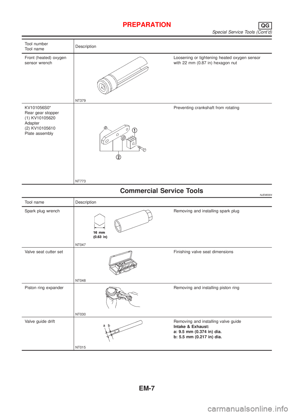
Tool number
Tool nameDescription
Front (heated) oxygen
sensor wrench
NT379
Loosening or tightening heated oxygen sensor
with 22 mm (0.87 in) hexagon nut
KV101056S0*
Rear gear stopper
(1) KV10105620
Adapter
(2) KV10105610
Plate assembly
NT773
Preventing crankshaft from rotating
Commercial Service ToolsNJEM0004
Tool name Description
Spark plug wrench
NT047
Removing and installing spark plug
Valve seat cutter set
NT048
Finishing valve seat dimensions
Piston ring expander
NT030
Removing and installing piston ring
Valve guide drift
NT015
Removing and installing valve guide
Intake & Exhaust:
a: 9.5 mm (0.374 in) dia.
b: 5.5 mm (0.217 in) dia.
PREPARATIONQG
Special Service Tools (Cont'd)
EM-7
Page 204 of 2493

JEM158G
SEM301G
3. Heat cylinder head to 110 to 120ÉC (230 to 248ÉF) by soaking
in heated oil.
4. Sufficiently cool valve seat with dry ice. Force fit valve seat into
cylinder head.
WARNING:
Do not touch cold valve seat with your bare hands.
5. Cut or grind valve seat using suitable tool to the specified
dimensions as shown in SDS (EM-163).
CAUTION:
Use the valve seat cutter properly. Securely gripping the cut-
ter handle with both hands, press the cutter down onto the
entire circumference of the contacting surface and finish cut-
ting at one time. Improper pressing of the cutter or cutting in
several steps may result in staged surface on the valve seat.
6. After cutting, lap valve seat with abrasive compound.
7. Check valve seating condition. Refer to EM-125, ªValve Seatsº.
JEM253G
8. Use a depth gauge to measure the distance between the
mounting surface of the cylinder head spring seat and the
valve stem end. If the distance is shorter than specified, repeat
step 5 above to adjust it. If it is longer, replace the valve seat
with a new one.
Valve seat resurface limit ªLº:
Intake 36.53 - 36.98 mm (1.4382 - 1.4559 in)
Exhaust 36.53 - 37.01 mm (1.4382 - 1.4571 in)
CYLINDER HEADYD
Inspection (Cont'd)
EM-126
Page 1895 of 2493
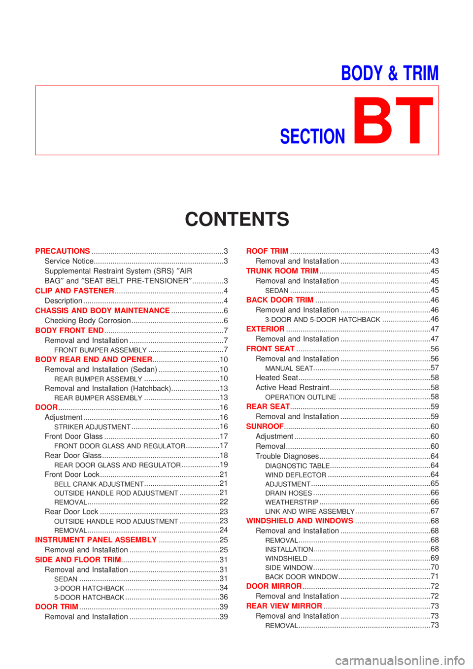
BODY & TRIM
SECTION
BT
CONTENTS
PRECAUTIONS...............................................................3
Service Notice..............................................................3
Supplemental Restraint System (SRS)²AIR
BAG²and²SEAT BELT PRE-TENSIONER²...............3
CLIP AND FASTENER....................................................4
Description ...................................................................4
CHASSIS AND BODY MAINTENANCE.........................6
Checking Body Corrosion ............................................6
BODY FRONT END.........................................................7
Removal and Installation .............................................7
FRONT BUMPER ASSEMBLY....................................7
BODY REAR END AND OPENER................................10
Removal and Installation (Sedan) .............................10
REAR BUMPER ASSEMBLY....................................10
Removal and Installation (Hatchback).......................13
REAR BUMPER ASSEMBLY....................................13
DOOR.............................................................................16
Adjustment .................................................................16
STRIKER ADJUSTMENT..........................................16
Front Door Glass .......................................................17
FRONT DOOR GLASS AND REGULATOR................17
Rear Door Glass ........................................................18
REAR DOOR GLASS AND REGULATOR..................19
Front Door Lock .........................................................21
BELL CRANK ADJUSTMENT....................................21
OUTSIDE HANDLE ROD ADJUSTMENT...................21
REMOVAL...............................................................22
Rear Door Lock .........................................................23
OUTSIDE HANDLE ROD ADJUSTMENT...................23
REMOVAL...............................................................24
INSTRUMENT PANEL ASSEMBLY.............................25
Removal and Installation ...........................................25
SIDE AND FLOOR TRIM...............................................31
Removal and Installation ...........................................31
SEDAN...................................................................31
3-DOOR HATCHBACK.............................................34
5-DOOR HATCHBACK.............................................36
DOOR TRIM...................................................................39
Removal and Installation ...........................................39ROOF TRIM...................................................................43
Removal and Installation ...........................................43
TRUNK ROOM TRIM.....................................................45
Removal and Installation ...........................................45
SEDAN...................................................................45
BACK DOOR TRIM.......................................................46
Removal and Installation ...........................................46
3-DOOR AND 5-DOOR HATCHBACK.......................46
EXTERIOR.....................................................................47
Removal and Installation ...........................................47
FRONT SEAT................................................................56
Removal and Installation ...........................................56
MANUAL SEAT........................................................57
Heated Seat ...............................................................58
Active Head Restraint ................................................58
OPERATION OUTLINE............................................58
REAR SEAT...................................................................59
Removal and Installation ...........................................59
SUNROOF......................................................................60
Adjustment .................................................................60
Removal .....................................................................60
Trouble Diagnoses.....................................................64
DIAGNOSTIC TABLE................................................64
WIND DEFLECTOR.................................................64
ADJUSTMENT.........................................................65
DRAIN HOSES........................................................66
WEATHERSTRIP.....................................................66
LINK AND WIRE ASSEMBLY....................................67
WINDSHIELD AND WINDOWS....................................68
Removal and Installation ...........................................68
REMOVAL...............................................................68
INSTALLATION........................................................68
WINDSHIELD..........................................................69
SIDE WINDOW........................................................70
BACK DOOR WINDOW............................................71
DOOR MIRROR.............................................................72
Removal and Installation ...........................................72
REAR VIEW MIRROR...................................................73
Removal and Installation ...........................................73
REMOVAL...............................................................73
Page 1950 of 2493
Removal and InstallationNJBT0018+When removing or installing the seat trim, carefully handle it to keep dirt out and avoid damage.
HFor Wiring Diagram, refer to EL-163, ªWiring Diagram Ð HEATED SEAT к.
CAUTION:
+Before removing the front seat, turn the ignition switch off, disconnect both battery cables and wait
at least 3 minutes.
+Do not drop, tilt, or bump the side air bag module installed in the seat. Always handle it with care.
+Disconnect the side air bag harness connector and heated seat harness connector from under the
seat before removing the seat.
+Disconnect the side air bag harness connector before removing the seat back. Refer to RS-33,
ªFront Side Air Bag Moduleº for details.
FRONT SEAT
Removal and Installation
BT-56
Page 1952 of 2493
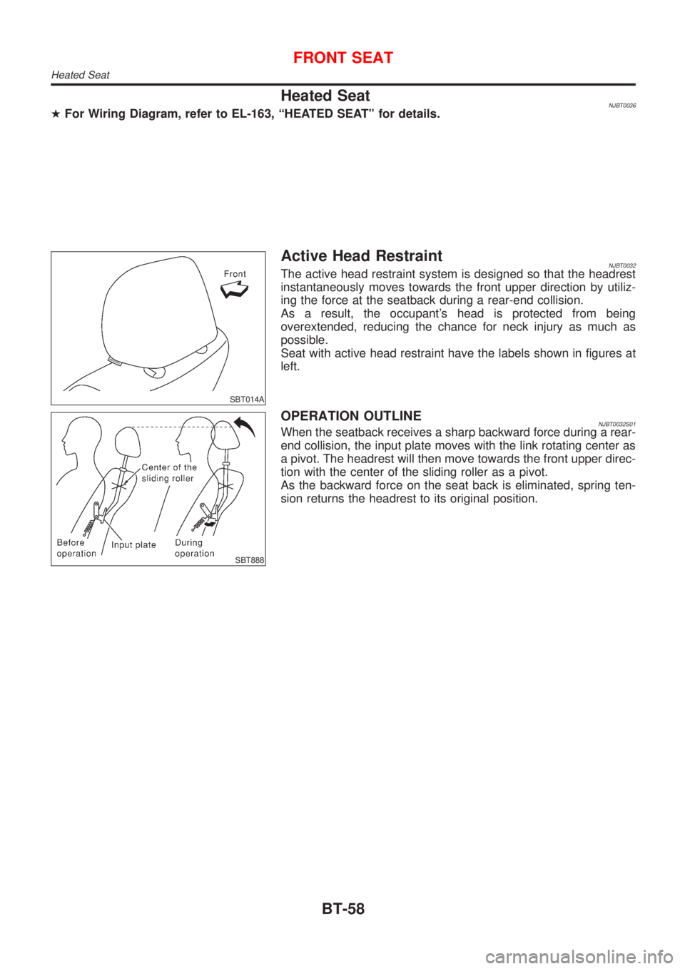
Heated SeatNJBT0036HFor Wiring Diagram, refer to EL-163, ªHEATED SEATº for details.
SBT014A
Active Head RestraintNJBT0032The active head restraint system is designed so that the headrest
instantaneously moves towards the front upper direction by utiliz-
ing the force at the seatback during a rear-end collision.
As a result, the occupant's head is protected from being
overextended, reducing the chance for neck injury as much as
possible.
Seat with active head restraint have the labels shown in figures at
left.
SBT888
OPERATION OUTLINENJBT0032S01When the seatback receives a sharp backward force during a rear-
end collision, the input plate moves with the link rotating center as
a pivot. The headrest will then move towards the front upper direc-
tion with the center of the sliding roller as a pivot.
As the backward force on the seat back is eliminated, spring ten-
sion returns the headrest to its original position.
FRONT SEAT
Heated Seat
BT-58
Page 1996 of 2493
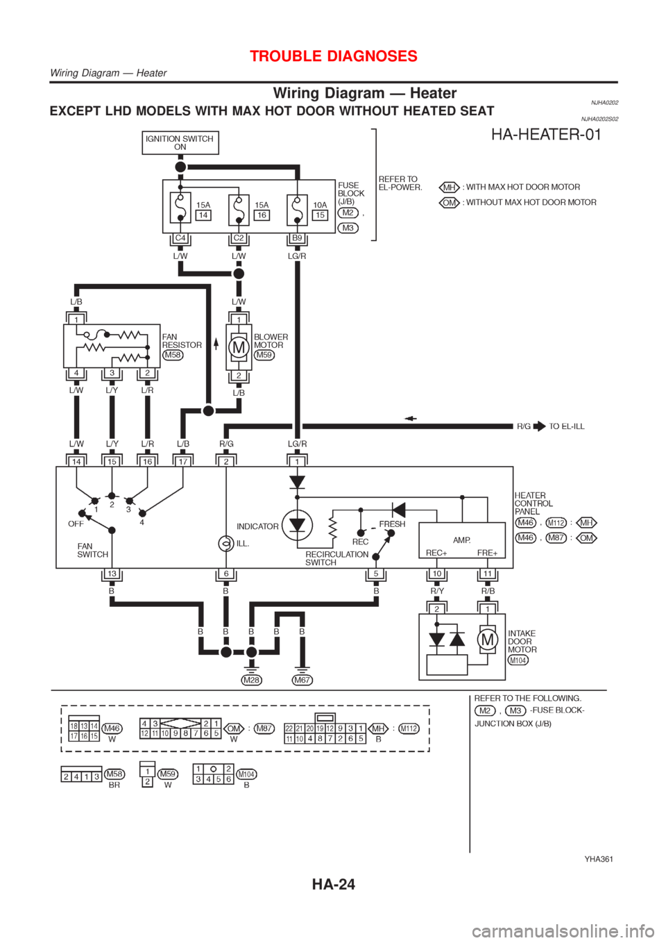
Wiring Diagram Ð HeaterNJHA0202EXCEPT LHD MODELS WITH MAX HOT DOOR WITHOUT HEATED SEATNJHA0202S02
YHA361
TROUBLE DIAGNOSES
Wiring Diagram Ð Heater
HA-24
Page 1997 of 2493
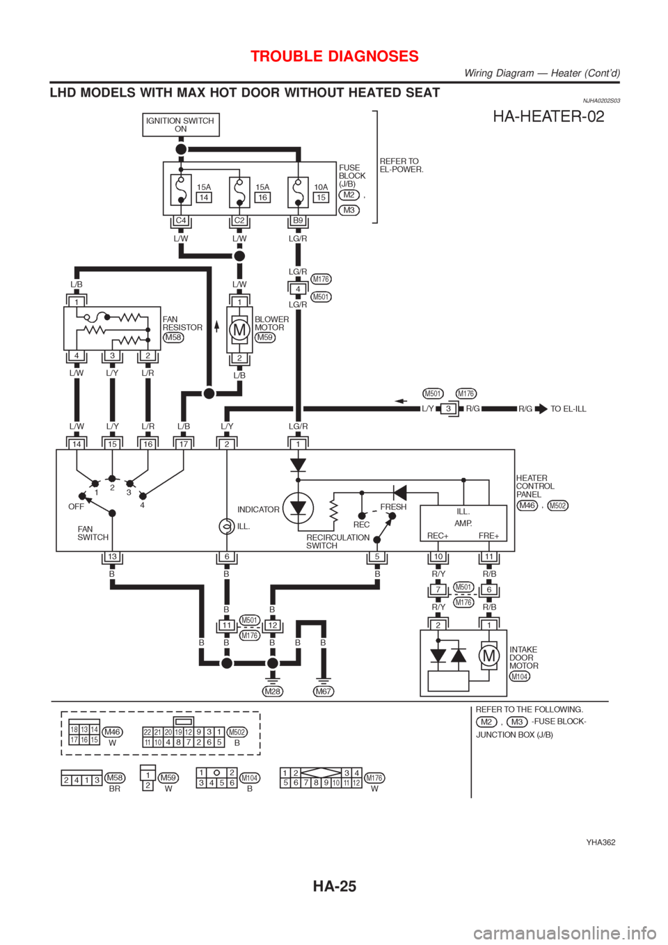
LHD MODELS WITH MAX HOT DOOR WITHOUT HEATED SEATNJHA0202S03
YHA362
TROUBLE DIAGNOSES
Wiring Diagram Ð Heater (Cont'd)
HA-25
Page 1999 of 2493
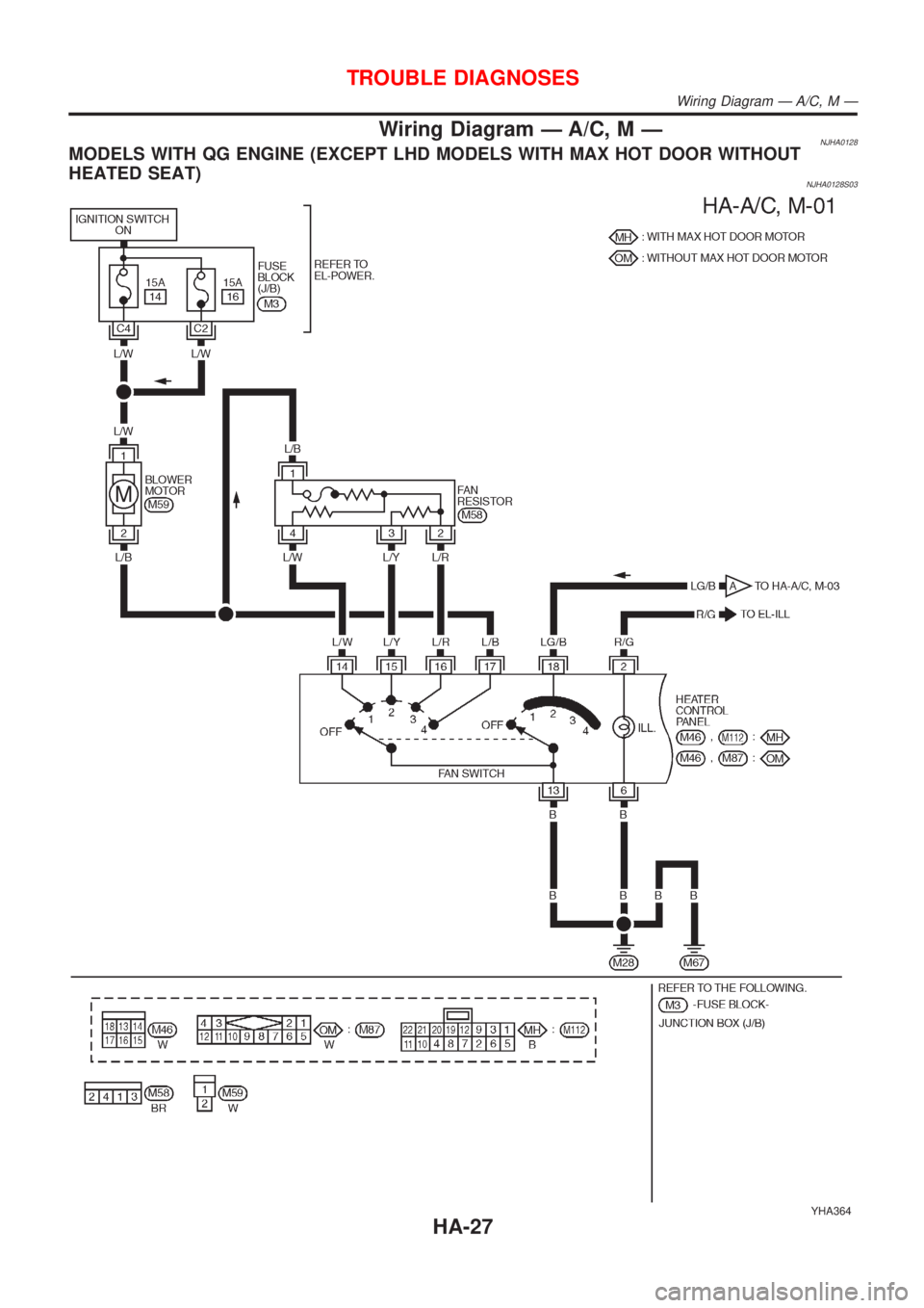
Wiring Diagram Ð A/C, M ÐNJHA0128MODELS WITH QG ENGINE (EXCEPT LHD MODELS WITH MAX HOT DOOR WITHOUT
HEATED SEAT)
NJHA0128S03
YHA364
TROUBLE DIAGNOSES
Wiring Diagram Ð A/C, M Ð
HA-27