Page 687 of 2493
Diagnostic ProcedureNJEC1246
1 CHECK OVERALL FUNCTION
Without CONSULT-II
1. Start engine and drive the vehicle at over 70 km/h (43 MPH) for 2 consecutive minutes.
2. Stop vehicle and keep the engine running.
3. Set the voltmeter probe between ECM terminals 3 [HO2S2 HTR (B1) signal] and ground.
4. Check the voltage under the following conditions.
SEF241Z
OK or NG
OK©INSPECTION END
NG©GO TO 2.
2 CHECK POWER SUPPLY
1. Turn ignition switch ªOFFº.
2. Disconnect heated oxygen sensor 2 (rear) harness connector.
NEF345A
3. Turn ignition switch ªONº.
4. Check voltage between terminal 2 and ground.
SEF218W
OK or NG
OK©GO TO 4.
NG©GO TO 3.
HEATED OXYGEN SENSOR 2 HEATER (REAR)QG
Diagnostic Procedure
EC-391
Page 815 of 2493

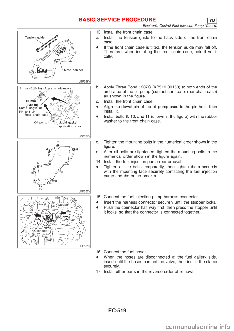
JEF369Y
13. Install the front chain case.
a. Install the tension guide to the back side of the front chain
case.
+If the front chain case is tilted, the tension guide may fall off.
Therefore, when installing the front chain case, hold it verti-
cally.
JEF370Y
b. Apply Three Bond 1207C (KP510 00150) to both ends of the
arch area of the oil pump (contact surface of rear chain case)
as shown in the figure.
c. Install the front chain case.
+Align the dowel pin of the oil pump case to the pin hole, then
install it.
+Install bolts 6, 10, and 11 (shown in the figure) with the rubber
washer to the front chain case.
JEF352Y
d. Tighten the mounting bolts in the numerical order shown in the
figure.
e. After all bolts are tightened, tighten the mounting bolts in the
numerical order shown in the figure again.
14. Install the fuel injection pump rear bracket.
+Tighten all the bolts temporarily, then tighten them securely
with the mounting face securely contacting the fuel injection
pump and the pump bracket.
JEF351Y
15. Connect the fuel injection pump harness connector.
+Insert the harness connector securely until the stopper locks.
+Push the connector half way first, then press the stopper until
it locks, so that the connector is connected together.
16. Connect the fuel hoses.
+When the hoses are disconnected at the fuel gallery side,
insert until the hoses contact the valve, then install the clamp
securely.
17. Install other parts in the reverse order of removal.
BASIC SERVICE PROCEDUREYD
Electronic Control Fuel Injection Pump (Cont'd)
EC-519
Page 822 of 2493
Relationship Between MI, DTC, CONSULT-II and Driving PatternsNJEC0628S07
SEF879Y
*1: When a malfunction is detected,
MI will light up.
*2: When the same malfunction is
detected in two consecutive driv-
ing patterns, MI will stay lit up.
*3: MI will go off after vehicle is driven
three times without any malfunc-
tions.*4: When a malfunction is detected
for the first time, the DTC will be
stored in ECM.
*5: The DTC will not be displayed any
longer after vehicle is driven 40
times without the same malfunc-
tion. (The DTC still remain in
ECM.)*6: Other screens except SELF-DIAG-
NOSTIC RESULTS & DATA
MONITOR (AUTO TRIG) cannot
display the malfunction. DATA
MONITOR (AUTO TRIG) can dis-
play the malfunction at the
moment it is detected.
ON BOARD DIAGNOSTIC SYSTEM DESCRIPTIONYD
Malfunction Indicator (MI) (Cont'd)
EC-526
Page 855 of 2493

DescriptionNJEC0637Intermittent incidents (I/I) may occur. In many cases, the problem resolves itself (the part or circuit function
returns to normal without intervention). It is important to realize that the symptoms described in the custom-
er's complaint often do not recur on DTC visits. Realize also that the most frequent cause of I/I occurrences
is poor electrical connections. Because of this, the conditions under which the incident occurred may not be
clear. Therefore, circuit checks made as part of the standard diagnostic procedure may not indicate the spe-
cific problem area.
COMMON I/I REPORT SITUATIONSNJEC0637S01
STEP in Work Flow Situation
II The CONSULT-II is used. The SELF-DIAG RESULTS screen shows time data other than ª0º.
III The symptom described by the customer does not recur.
IV DTC does not appear during the DTC Confirmation Procedure.
VI The Diagnostic Procedure for XXXX does not indicate the problem area.
Diagnostic ProcedureNJEC0638
1 INSPECTION START
Erase DTCs. Refer to ªHOW TO ERASE DTCº, EC-522.
©GO TO 2.
2 CHECK GROUND TERMINALS
Check ground terminals for corroding or loose connection.
Refer to GI-22, ªGROUND INSPECTIONº.
OK or NG
OK©GO TO 3.
NG©Repair or replace.
3 SEARCH FOR ELECTRICAL INCIDENT
Perform GI-22, ªIncident Simulation Testsº.
OK or NG
OK©INSPECTION END
NG©Repair or replace.
TROUBLE DIAGNOSIS FOR INTERMITTENT INCIDENTYD
Description
EC-559
Page 1002 of 2493
SFE248AB
4. Loosen lock nut.
5. Tighten accelerator adjusting nut until throttle drum starts to
move.
6. From that position, turn back adjusting nut 1.5 to 2 turns, and
secure lock nut.
7. Release vacuum from the throttle opener.
8. Remove vacuum pump and vacuum hose from the throttle
opener.
9. Reinstall the original vacuum hose to the throttle opener
securely.
ACCELERATOR CONTROL SYSTEMQG
Adjusting Accelerator Wire (Cont'd)
FE-4
Page 1003 of 2493

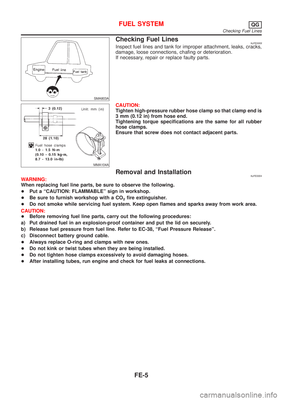
SMA803A
Checking Fuel LinesNJFE0009Inspect fuel lines and tank for improper attachment, leaks, cracks,
damage, loose connections, chafing or deterioration.
If necessary, repair or replace faulty parts.
MMA104A
CAUTION:
Tighten high-pressure rubber hose clamp so that clamp end is
3 mm (0.12 in) from hose end.
Tightening torque specifications are the same for all rubber
hose clamps.
Ensure that screw does not contact adjacent parts.
Removal and InstallationNJFE0004WARNING:
When replacing fuel line parts, be sure to observe the following.
+Put a ªCAUTION: FLAMMABLEº sign in workshop.
+Be sure to furnish workshop with a CO
2fire extinguisher.
+Do not smoke while servicing fuel system. Keep open flames and sparks away from work area.
CAUTION:
+Before removing fuel line parts, carry out the following procedures:
a) Put drained fuel in an explosion-proof container and put the lid on securely.
b) Release fuel pressure from fuel line. Refer to EC-38, ªFuel Pressure Releaseº.
c) Disconnect battery ground cable.
+Always replace O-ring and clamps with new ones.
+Do not kink or twist tubes when they are being installed.
+Do not tighten hose clamps excessively to avoid damaging hoses.
+After installing tubes, run engine and check for fuel leaks at connections.
FUEL SYSTEMQG
Checking Fuel Lines
FE-5
Page 1013 of 2493

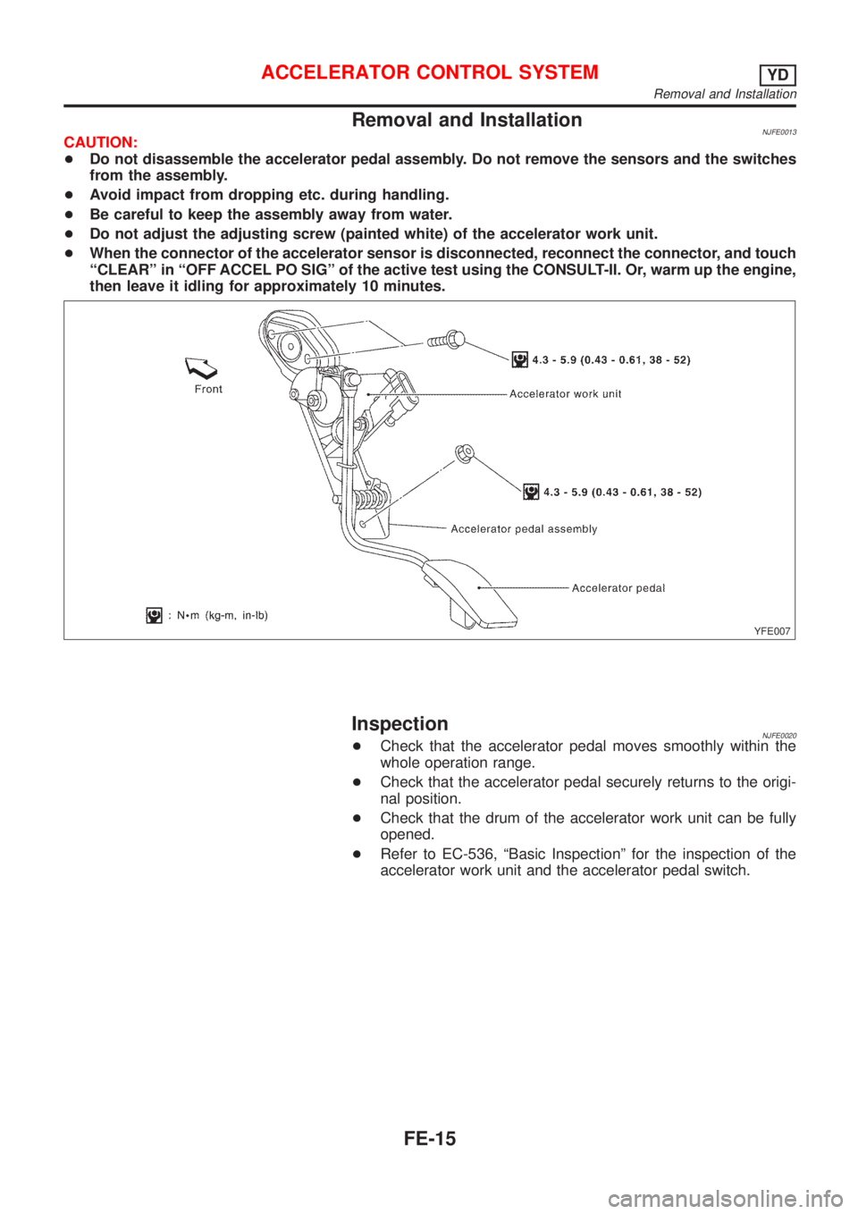
Removal and InstallationNJFE0013CAUTION:
+Do not disassemble the accelerator pedal assembly. Do not remove the sensors and the switches
from the assembly.
+Avoid impact from dropping etc. during handling.
+Be careful to keep the assembly away from water.
+Do not adjust the adjusting screw (painted white) of the accelerator work unit.
+When the connector of the accelerator sensor is disconnected, reconnect the connector, and touch
ªCLEARº in ªOFF ACCEL PO SIGº of the active test using the CONSULT-II. Or, warm up the engine,
then leave it idling for approximately 10 minutes.
YFE007
InspectionNJFE0020+Check that the accelerator pedal moves smoothly within the
whole operation range.
+Check that the accelerator pedal securely returns to the origi-
nal position.
+Check that the drum of the accelerator work unit can be fully
opened.
+Refer to EC-536, ªBasic Inspectionº for the inspection of the
accelerator work unit and the accelerator pedal switch.
ACCELERATOR CONTROL SYSTEMYD
Removal and Installation
FE-15
Page 1015 of 2493

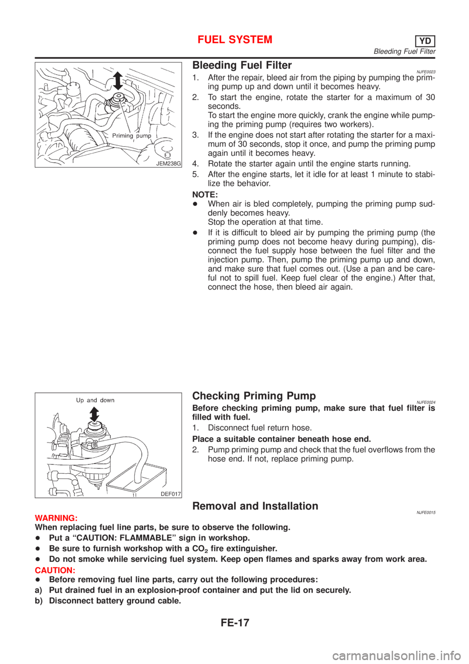
JEM238G
Bleeding Fuel FilterNJFE00231. After the repair, bleed air from the piping by pumping the prim-
ing pump up and down until it becomes heavy.
2. To start the engine, rotate the starter for a maximum of 30
seconds.
To start the engine more quickly, crank the engine while pump-
ing the priming pump (requires two workers).
3. If the engine does not start after rotating the starter for a maxi-
mum of 30 seconds, stop it once, and pump the priming pump
again until it becomes heavy.
4. Rotate the starter again until the engine starts running.
5. After the engine starts, let it idle for at least 1 minute to stabi-
lize the behavior.
NOTE:
+When air is bled completely, pumping the priming pump sud-
denly becomes heavy.
Stop the operation at that time.
+If it is difficult to bleed air by pumping the priming pump (the
priming pump does not become heavy during pumping), dis-
connect the fuel supply hose between the fuel filter and the
injection pump. Then, pump the priming pump up and down,
and make sure that fuel comes out. (Use a pan and be care-
ful not to spill fuel. Keep fuel clear of the engine.) After that,
connect the hose, then bleed air again.
DEF017
Checking Priming PumpNJFE0024Before checking priming pump, make sure that fuel filter is
filled with fuel.
1. Disconnect fuel return hose.
Place a suitable container beneath hose end.
2. Pump priming pump and check that the fuel overflows from the
hose end. If not, replace priming pump.
Removal and InstallationNJFE0015WARNING:
When replacing fuel line parts, be sure to observe the following.
+Put a ªCAUTION: FLAMMABLEº sign in workshop.
+Be sure to furnish workshop with a CO
2fire extinguisher.
+Do not smoke while servicing fuel system. Keep open flames and sparks away from work area.
CAUTION:
+Before removing fuel line parts, carry out the following procedures:
a) Put drained fuel in an explosion-proof container and put the lid on securely.
b) Disconnect battery ground cable.
FUEL SYSTEMYD
Bleeding Fuel Filter
FE-17