Page 1012 of 2493
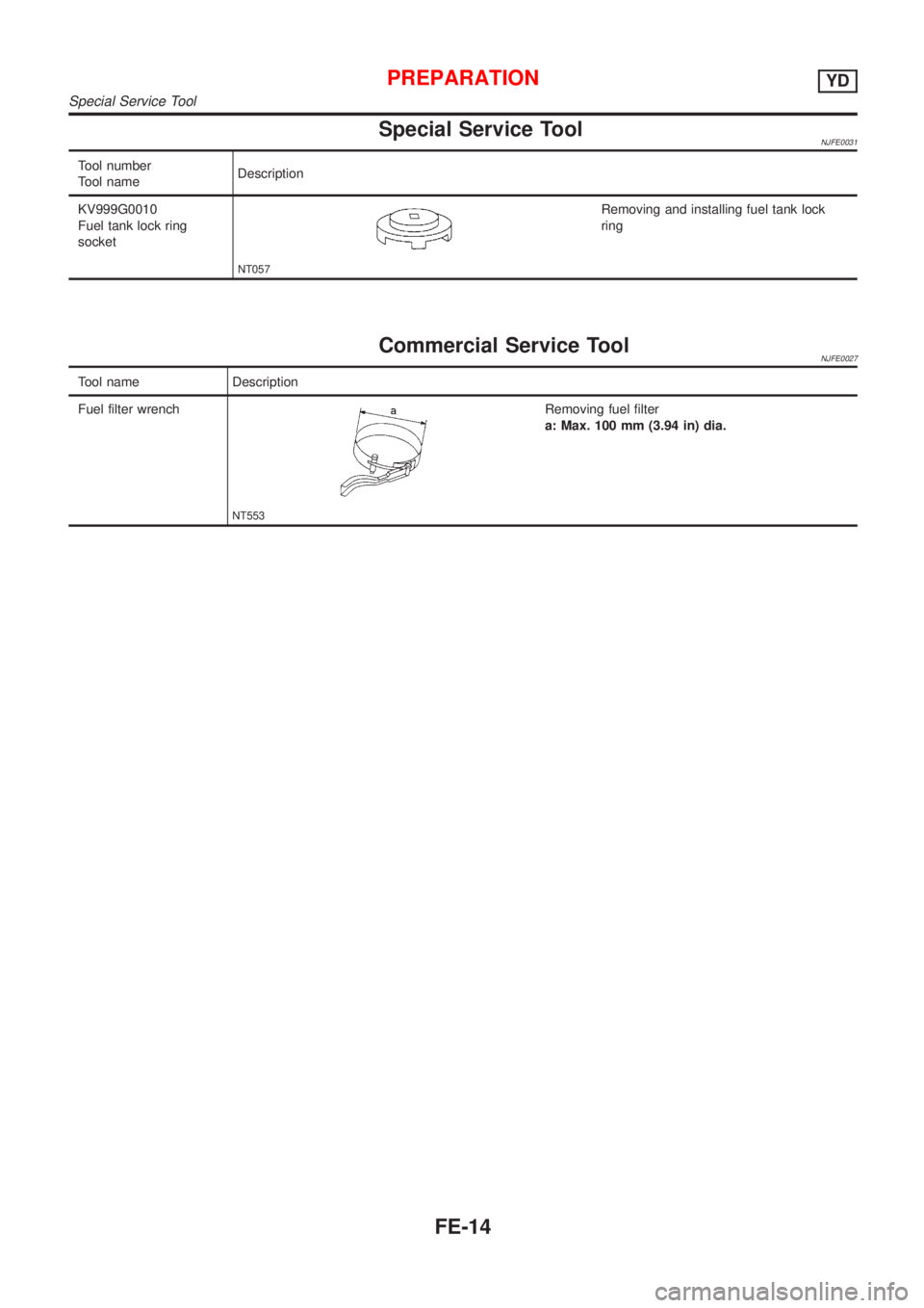
Special Service ToolNJFE0031
Tool number
Tool nameDescription
KV999G0010
Fuel tank lock ring
socket
NT057
Removing and installing fuel tank lock
ring
Commercial Service ToolNJFE0027
Tool name Description
Fuel filter wrench
NT553
Removing fuel filter
a: Max. 100 mm (3.94 in) dia.
PREPARATIONYD
Special Service Tool
FE-14
Page 1014 of 2493
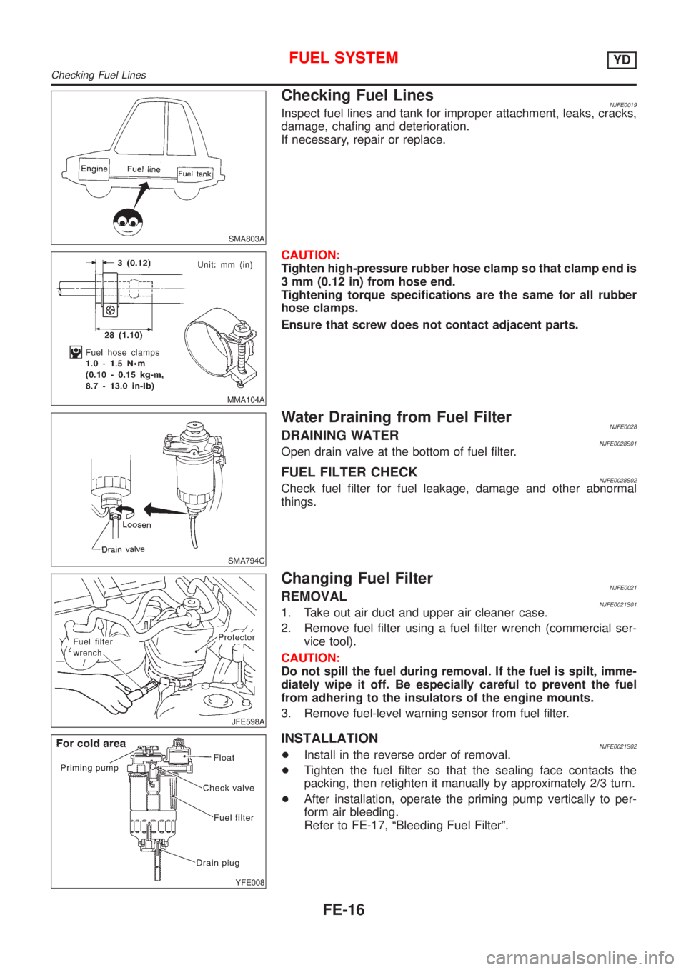
SMA803A
Checking Fuel LinesNJFE0019Inspect fuel lines and tank for improper attachment, leaks, cracks,
damage, chafing and deterioration.
If necessary, repair or replace.
MMA104A
CAUTION:
Tighten high-pressure rubber hose clamp so that clamp end is
3 mm (0.12 in) from hose end.
Tightening torque specifications are the same for all rubber
hose clamps.
Ensure that screw does not contact adjacent parts.
SMA794C
Water Draining from Fuel FilterNJFE0028DRAINING WATERNJFE0028S01Open drain valve at the bottom of fuel filter.
FUEL FILTER CHECKNJFE0028S02Check fuel filter for fuel leakage, damage and other abnormal
things.
JFE598A
Changing Fuel FilterNJFE0021REMOVALNJFE0021S011. Take out air duct and upper air cleaner case.
2. Remove fuel filter using a fuel filter wrench (commercial ser-
vice tool).
CAUTION:
Do not spill the fuel during removal. If the fuel is spilt, imme-
diately wipe it off. Be especially careful to prevent the fuel
from adhering to the insulators of the engine mounts.
3. Remove fuel-level warning sensor from fuel filter.
YFE008
INSTALLATIONNJFE0021S02+Install in the reverse order of removal.
+Tighten the fuel filter so that the sealing face contacts the
packing, then retighten it manually by approximately 2/3 turn.
+After installation, operate the priming pump vertically to per-
form air bleeding.
Refer to FE-17, ªBleeding Fuel Filterº.
FUEL SYSTEMYD
Checking Fuel Lines
FE-16
Page 1015 of 2493
JEM238G
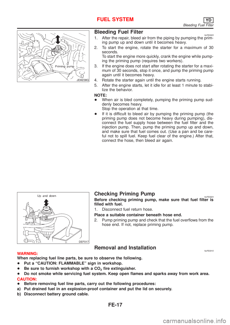
Bleeding Fuel FilterNJFE00231. After the repair, bleed air from the piping by pumping the prim-
ing pump up and down until it becomes heavy.
2. To start the engine, rotate the starter for a maximum of 30
seconds.
To start the engine more quickly, crank the engine while pump-
ing the priming pump (requires two workers).
3. If the engine does not start after rotating the starter for a maxi-
mum of 30 seconds, stop it once, and pump the priming pump
again until it becomes heavy.
4. Rotate the starter again until the engine starts running.
5. After the engine starts, let it idle for at least 1 minute to stabi-
lize the behavior.
NOTE:
+When air is bled completely, pumping the priming pump sud-
denly becomes heavy.
Stop the operation at that time.
+If it is difficult to bleed air by pumping the priming pump (the
priming pump does not become heavy during pumping), dis-
connect the fuel supply hose between the fuel filter and the
injection pump. Then, pump the priming pump up and down,
and make sure that fuel comes out. (Use a pan and be care-
ful not to spill fuel. Keep fuel clear of the engine.) After that,
connect the hose, then bleed air again.
DEF017
Checking Priming PumpNJFE0024Before checking priming pump, make sure that fuel filter is
filled with fuel.
1. Disconnect fuel return hose.
Place a suitable container beneath hose end.
2. Pump priming pump and check that the fuel overflows from the
hose end. If not, replace priming pump.
Removal and InstallationNJFE0015WARNING:
When replacing fuel line parts, be sure to observe the following.
+Put a ªCAUTION: FLAMMABLEº sign in workshop.
+Be sure to furnish workshop with a CO
2fire extinguisher.
+Do not smoke while servicing fuel system. Keep open flames and sparks away from work area.
CAUTION:
+Before removing fuel line parts, carry out the following procedures:
a) Put drained fuel in an explosion-proof container and put the lid on securely.
b) Disconnect battery ground cable.
FUEL SYSTEMYD
Bleeding Fuel Filter
FE-17
Page 1042 of 2493
SCL729
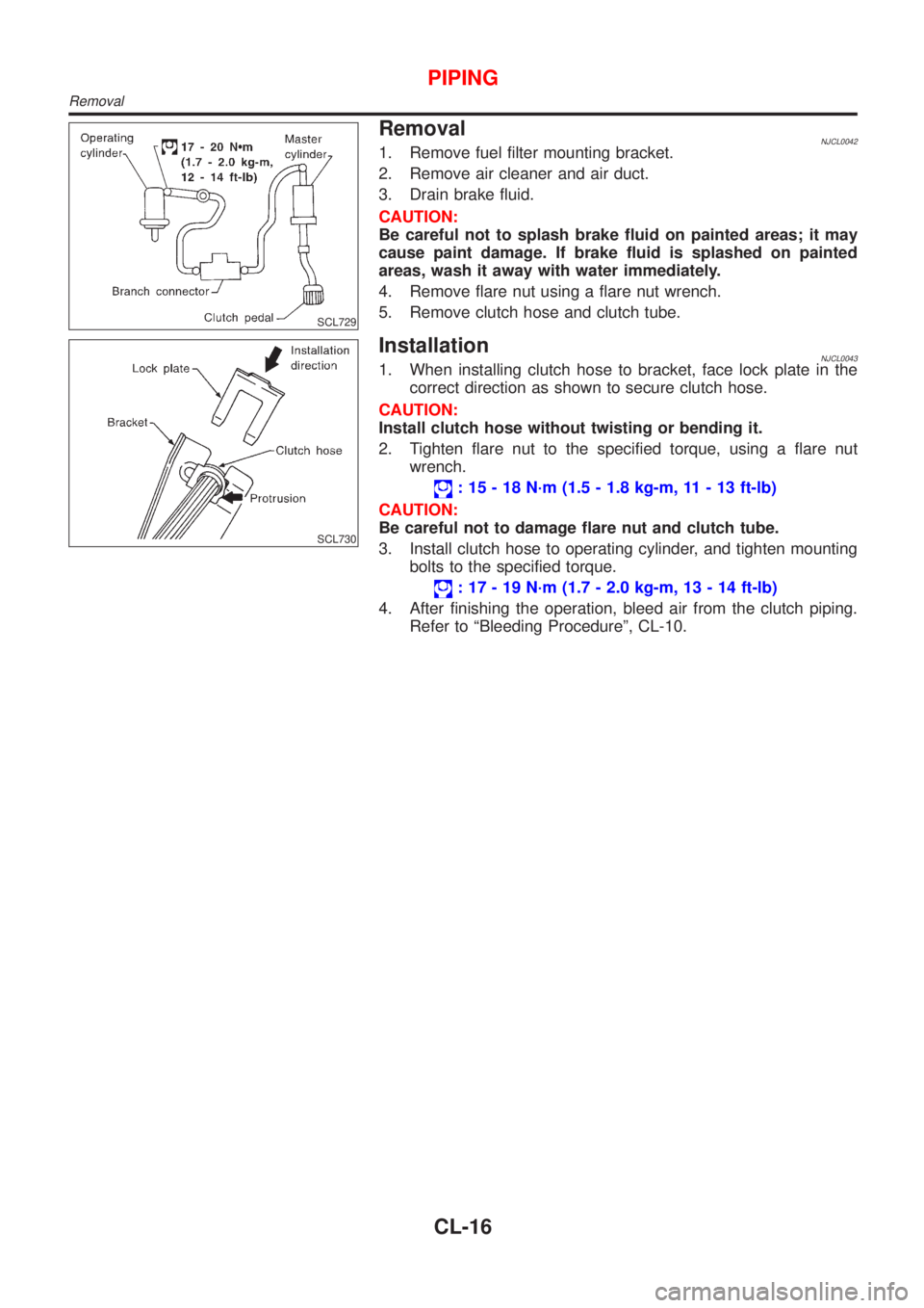
RemovalNJCL00421. Remove fuel filter mounting bracket.
2. Remove air cleaner and air duct.
3. Drain brake fluid.
CAUTION:
Be careful not to splash brake fluid on painted areas; it may
cause paint damage. If brake fluid is splashed on painted
areas, wash it away with water immediately.
4. Remove flare nut using a flare nut wrench.
5. Remove clutch hose and clutch tube.
SCL730
InstallationNJCL00431. When installing clutch hose to bracket, face lock plate in the
correct direction as shown to secure clutch hose.
CAUTION:
Install clutch hose without twisting or bending it.
2. Tighten flare nut to the specified torque, using a flare nut
wrench.
: 15 - 18 N´m (1.5 - 1.8 kg-m, 11 - 13 ft-lb)
CAUTION:
Be careful not to damage flare nut and clutch tube.
3. Install clutch hose to operating cylinder, and tighten mounting
bolts to the specified torque.
: 17 - 19 N´m (1.7 - 2.0 kg-m, 13 - 14 ft-lb)
4. After finishing the operation, bleed air from the clutch piping.
Refer to ªBleeding Procedureº, CL-10.
PIPING
Removal
CL-16
Page 1077 of 2493
SMT940D
SMT951D
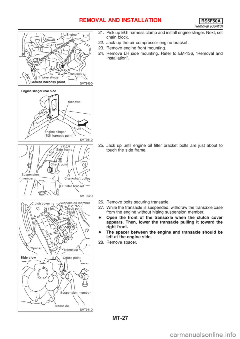
21. Pick up EGI harness clamp and install engine slinger. Next, set
chain block.
22. Jack up the air compressor engine bracket.
23. Remove engine front mounting.
24. Remove LH side mounting. Refer to EM-136, ªRemoval and
Installationº.
SMT952D
25. Jack up until engine oil filter bracket bolts are just about to
touch the side frame.
SMT941D
26. Remove bolts securing transaxle.
27. While the transaxle is suspended, withdraw the transaxle case
from the engine without hitting suspension member.
+Open the front of the transaxle when the clutch cover
appears. Then, lower the transaxle pulling it toward the
right front.
+The spacer between the engine and transaxle should be
left at the engine side.
28. Remove spacer.
REMOVAL AND INSTALLATIONRS5F50A
Removal (Cont'd)
MT-27
Page 1195 of 2493
parts. Apply petroleum jelly to protect O-rings and seals, or
hold bearings and washers in place during assembly. Do not
use grease.
+Extreme care should be taken to avoid damage to O-rings,
seals and gaskets when assembling.
+After overhaul, refill the transaxle with new ATF.
+When the A/T drain plug is removed, only some of the fluid is
drained. Old A/T fluid will remain in torque converter and ATF
cooling system.
Always follow the procedures under ªChanging A/T Fluidº in the
AT section when changing A/T fluid. Refer to ªChanging A/T
Fluidº, AT-15.
Service Notice or PrecautionsNJAT0247FAIL-SAFENJAT0247S01The TCM has an electronic Fail-Safe (limp home mode). This allows the vehicle to be driven even if a major
electrical input/output device circuit is damaged.
Under Fail-Safe, the vehicle always runs in third gear, even with a shift lever position of ª1º, ª2º or ªDº. The
customer may complain of sluggish or poor acceleration.
When the ignition key is turned ªONº following Fail-Safe operation, O/D OFF indicator lamp blinks for about
8 seconds. (For EXCEPT FOR EURO-OBD; ªSELF-DIAGNOSTIC PROCEDURE (WITHOUT CONSULT-II)º,
refer to AT-42 and for EURO-OBD; ªTCM SELF-DIAGNOSTIC PROCEDURE (No Tools)º, refer to AT-61.)
Fail-Safe may occur without electrical circuit damage if the vehicle is driven under extreme conditions (such
as excessive wheel spin followed by sudden braking). To recover normal shift pattern, turn the ignition key
ªOFFº for 5 seconds, then ªONº.
The blinking of the O/D OFF indicator lamp for about 8 seconds will appear only once and be cleared. The
customer may resume normal driving conditions.
Always follow the ªWORK FLOWº [Refer to AT-71 (Except for Euro-OBD), AT-76 (EURO-OBD).]
The SELF-DIAGNOSIS results will be as follows:
The first SELF-DIAGNOSIS will indicate damage to the vehicle speed sensor or the revolution sensor.
During the next SELF-DIAGNOSIS, performed after checking the sensor, no damages will be indicated.
TORQUE CONVERTER SERVICENJAT0247S02The torque converter should be replaced under any of the following conditions:
+External leaks in the hub weld area.
+Converter hub is scored or damaged.
+Converter pilot is broken, damaged or fits poorly into crankshaft.
+Steel particles are found after flushing the cooler and cooler lines.
+Pump is damaged or steel particles are found in the converter.
+Vehicle has TCC shudder and/or no TCC apply. Replace only after all hydraulic and electrical diagnoses
have been made. (Converter clutch material may be glazed.)
+Converter is contaminated with engine coolant containing antifreeze.
+Internal failure of stator roller clutch.
+Heavy clutch debris due to overheating (blue converter).
+Steel particles or clutch lining material found in fluid filter or on magnet when no internal parts in unit are
worn or damaged Ð indicates that lining material came from converter.
The torque converter should not be replaced if:
PRECAUTIONS
Precautions (Cont'd)
AT-9
Page 1196 of 2493

+The fluid has an odor, is discolored, and there is no evidence of metal or clutch facing particles.
+The threads in one or more of the converter bolt holes are damaged.
+Transaxle failure did not display evidence of damaged or worn internal parts, steel particles or clutch plate
lining material in unit and inside the fluid filter.
+Vehicle has been exposed to high mileage (only). The exception may be where the torque converter clutch
dampener plate lining has seen excess wear by vehicles operated in heavy and/or constant traffic, such
as taxi, delivery or police use.
EURO-OBD SELF-DIAGNOSIS Ð EURO-OBD ÐNJAT0247S04+A/T self-diagnosis is performed by the TCM in combination with the ECM. The results can be read through
the blinking pattern of the O/D OFF indicator or the malfunction indicator (MI). Refer to the table on AT-53
for the indicator used to display each self-diagnostic result.
+The self-diagnostic results indicated by the MI are automatically stored in both the ECM and TCM memo-
ries.
Always perform the procedure ªHOW TO ERASE DTCº on AT-50 to complete the repair and avoid
unnecessary blinking of the MI.
+The following self-diagnostic items can be detected using ECM self-diagnostic results mode* only when
the O/D OFF indicator lamp does not indicate any malfunctions.
þ PNP switch
þ A/T 1st, 2nd, 3rd, or 4th gear function
*: For details of EURO-OBD, refer to EC-57, ªON BOARD DIAGNOSTIC SYSTEM DESCRIPTIONº.
+Certain systems and components, especially those related to EURO-OBD, may use a new style
slide-locking type harness connector.
For description and how to disconnect, refer to EL-5, ªHARNESS CONNECTORº.
Wiring Diagrams and Trouble DiagnosisNJAT0248When you read wiring diagrams, refer to the following:
+GI-12, ªHOW TO READ WIRING DIAGRAMSº
+EL-10, ªPOWER SUPPLY ROUTINGº
When you perform trouble diagnosis, refer to the following:
+GI-32, ªHOW TO FOLLOW TEST GROUP IN TROUBLE DIAGNOSISº
+GI-21, ªHOW TO PERFORM EFFICIENT DIAGNOSIS FOR AN ELECTRICAL INCIDENTº
PRECAUTIONS
Service Notice or Precautions (Cont'd)
AT-10
Page 1482 of 2493
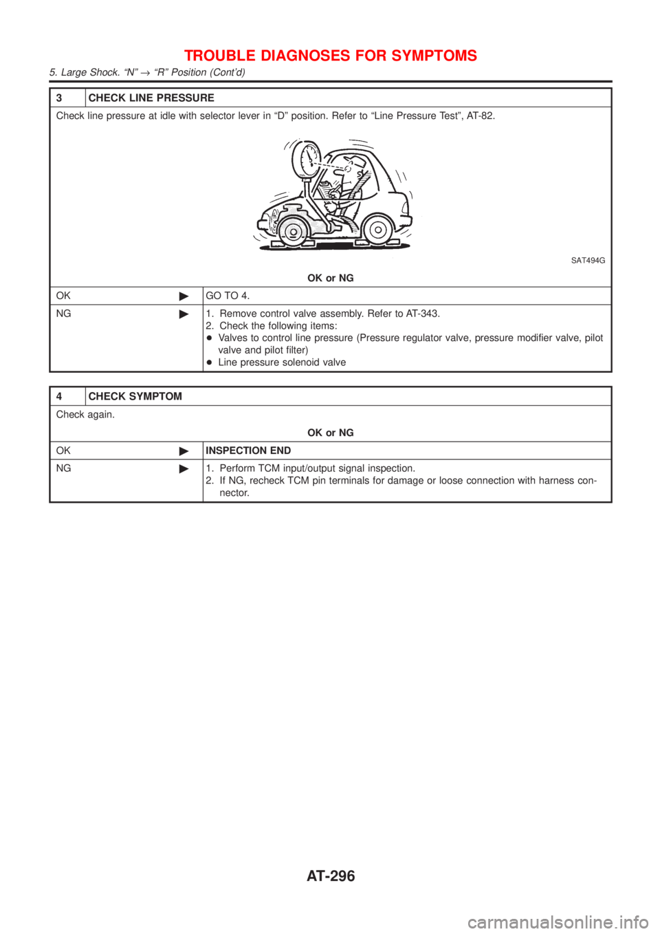
3 CHECK LINE PRESSURE
Check line pressure at idle with selector lever in ªDº position. Refer to ªLine Pressure Testº, AT-82.
SAT494G
OK or NG
OK©GO TO 4.
NG©1. Remove control valve assembly. Refer to AT-343.
2. Check the following items:
+Valves to control line pressure (Pressure regulator valve, pressure modifier valve, pilot
valve and pilot filter)
+Line pressure solenoid valve
4 CHECK SYMPTOM
Check again.
OK or NG
OK©INSPECTION END
NG©1. Perform TCM input/output signal inspection.
2. If NG, recheck TCM pin terminals for damage or loose connection with harness con-
nector.
TROUBLE DIAGNOSES FOR SYMPTOMS
5. Large Shock. ªNº®ªRº Position (Cont'd)
AT-296