2001 NISSAN ALMERA N16 Ignition
[x] Cancel search: IgnitionPage 1517 of 2493
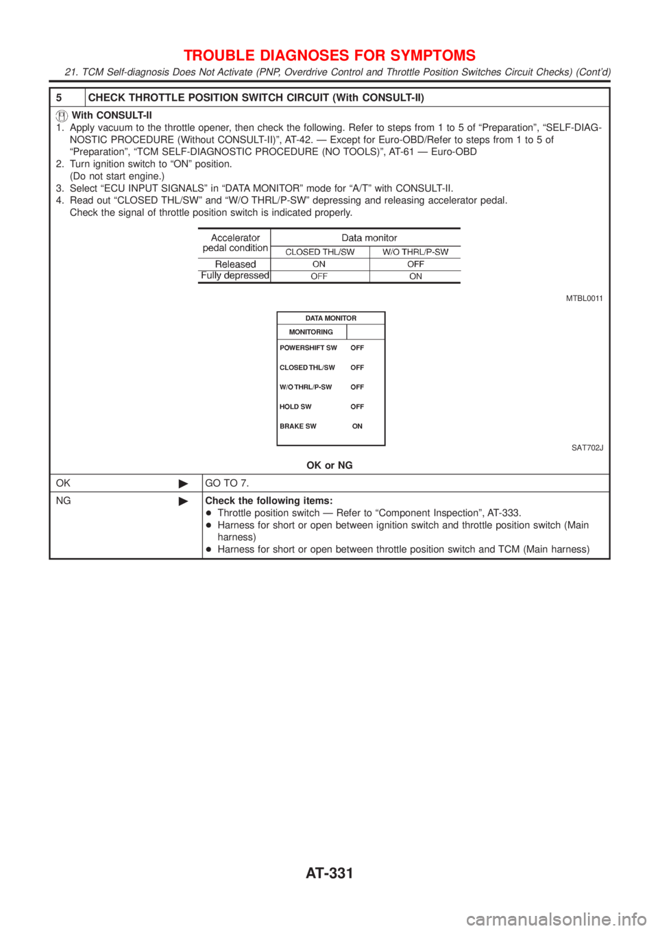
5 CHECK THROTTLE POSITION SWITCH CIRCUIT (With CONSULT-II)
With CONSULT-II
1. Apply vacuum to the throttle opener, then check the following. Refer to steps from 1 to 5 of ªPreparationº, ªSELF-DIAG-
NOSTIC PROCEDURE (Without CONSULT-II)º, AT-42. Ð Except for Euro-OBD/Refer to steps from 1 to 5 of
ªPreparationº, ªTCM SELF-DIAGNOSTIC PROCEDURE (NO TOOLS)º, AT-61 Ð Euro-OBD
2. Turn ignition switch to ªONº position.
(Do not start engine.)
3. Select ªECU INPUT SIGNALSº in ªDATA MONITORº mode for ªA/Tº with CONSULT-II.
4. Read out ªCLOSED THL/SWº and ªW/O THRL/P-SWº depressing and releasing accelerator pedal.
Check the signal of throttle position switch is indicated properly.
MTBL0011
SAT702J
OK or NG
OK©GO TO 7.
NG©Check the following items:
+Throttle position switch Ð Refer to ªComponent Inspectionº, AT-333.
+Harness for short or open between ignition switch and throttle position switch (Main
harness)
+Harness for short or open between throttle position switch and TCM (Main harness)
TROUBLE DIAGNOSES FOR SYMPTOMS
21. TCM Self-diagnosis Does Not Activate (PNP, Overdrive Control and Throttle Position Switches Circuit Checks) (Cont'd)
AT-331
Page 1518 of 2493
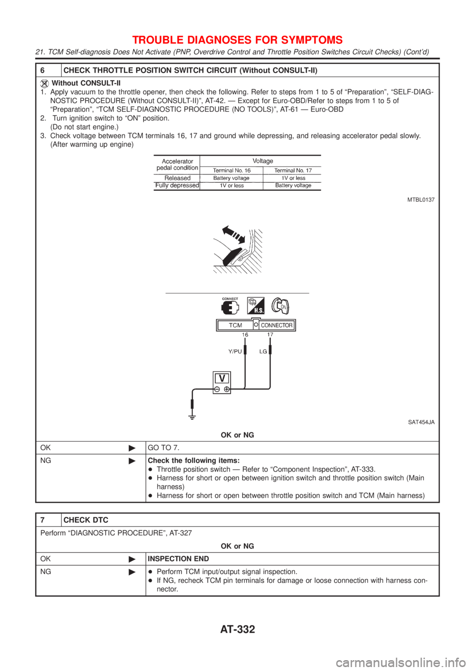
6 CHECK THROTTLE POSITION SWITCH CIRCUIT (Without CONSULT-II)
Without CONSULT-II
1. Apply vacuum to the throttle opener, then check the following. Refer to steps from 1 to 5 of ªPreparationº, ªSELF-DIAG-
NOSTIC PROCEDURE (Without CONSULT-II)º, AT-42. Ð Except for Euro-OBD/Refer to steps from 1 to 5 of
ªPreparationº, ªTCM SELF-DIAGNOSTIC PROCEDURE (NO TOOLS)º, AT-61 Ð Euro-OBD
2. Turn ignition switch to ªONº position.
(Do not start engine.)
3. Check voltage between TCM terminals 16, 17 and ground while depressing, and releasing accelerator pedal slowly.
(After warming up engine)
MTBL0137
SAT454JA
OK or NG
OK©GO TO 7.
NG©Check the following items:
+Throttle position switch Ð Refer to ªComponent Inspectionº, AT-333.
+Harness for short or open between ignition switch and throttle position switch (Main
harness)
+Harness for short or open between throttle position switch and TCM (Main harness)
7 CHECK DTC
Perform ªDIAGNOSTIC PROCEDUREº, AT-327
OK or NG
OK©INSPECTION END
NG©+Perform TCM input/output signal inspection.
+If NG, recheck TCM pin terminals for damage or loose connection with harness con-
nector.
TROUBLE DIAGNOSES FOR SYMPTOMS
21. TCM Self-diagnosis Does Not Activate (PNP, Overdrive Control and Throttle Position Switches Circuit Checks) (Cont'd)
AT-332
Page 1523 of 2493
Diagnostic ProcedureNJAT0105SYMPTOM 1:
+Selector lever cannot be moved from ªPº position with key
in ON position and brake pedal applied.
+Selector lever can be moved from ªPº position with key in
ON position and brake pedal released.
+Selector lever can be moved from ªPº position when key
is removed from key cylinder.
SYMPTOM 2:
Ignition key cannot be removed when selector lever is set to
ªPº position. It can be removed when selector lever is set to
any position except ªPº.
1 CHECK KEY INTERLOCK CABLE
Check key interlock cable for damage.
OK or NG
OK©GO TO 2.
NG©Repair key interlock cable. Refer to AT-341.
2 CHECK SELECTOR LEVER POSITION
Check selector lever position for damage.
OK or NG
OK©GO TO 3.
NG©Check selector lever. Refer to ªON-VEHICLE SERVICE Ð PNP Switch and Control
Cable Adjustmentº, AT-344.
3 CHECK POWER SOURCE
1. Turn ignition switch to ªONº position.
(Do not start engine.)
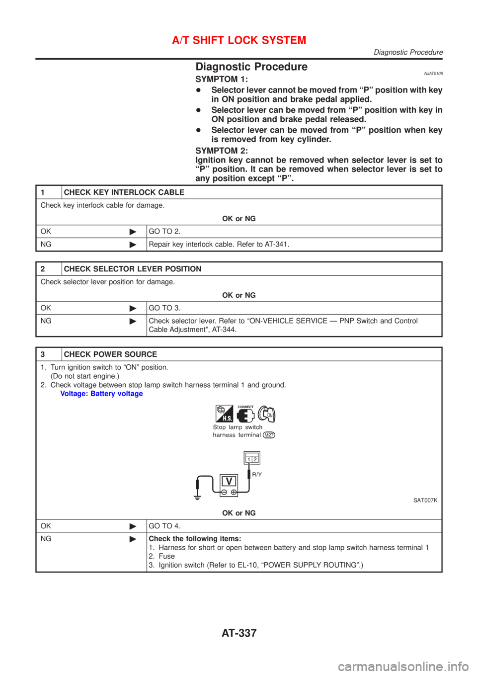
2. Check voltage between stop lamp switch harness terminal 1 and ground.
Voltage: Battery voltage
SAT007K
OK or NG
OK©GO TO 4.
NG©Check the following items:
1. Harness for short or open between battery and stop lamp switch harness terminal 1
2. Fuse
3. Ignition switch (Refer to EL-10, ªPOWER SUPPLY ROUTINGº.)
A/T SHIFT LOCK SYSTEM
Diagnostic Procedure
AT-337
Page 1524 of 2493
4 CHECK INPUT SIGNAL (A/T DEVICE)
Turn ignition switch to ªONº position.
(Do not start engine.)
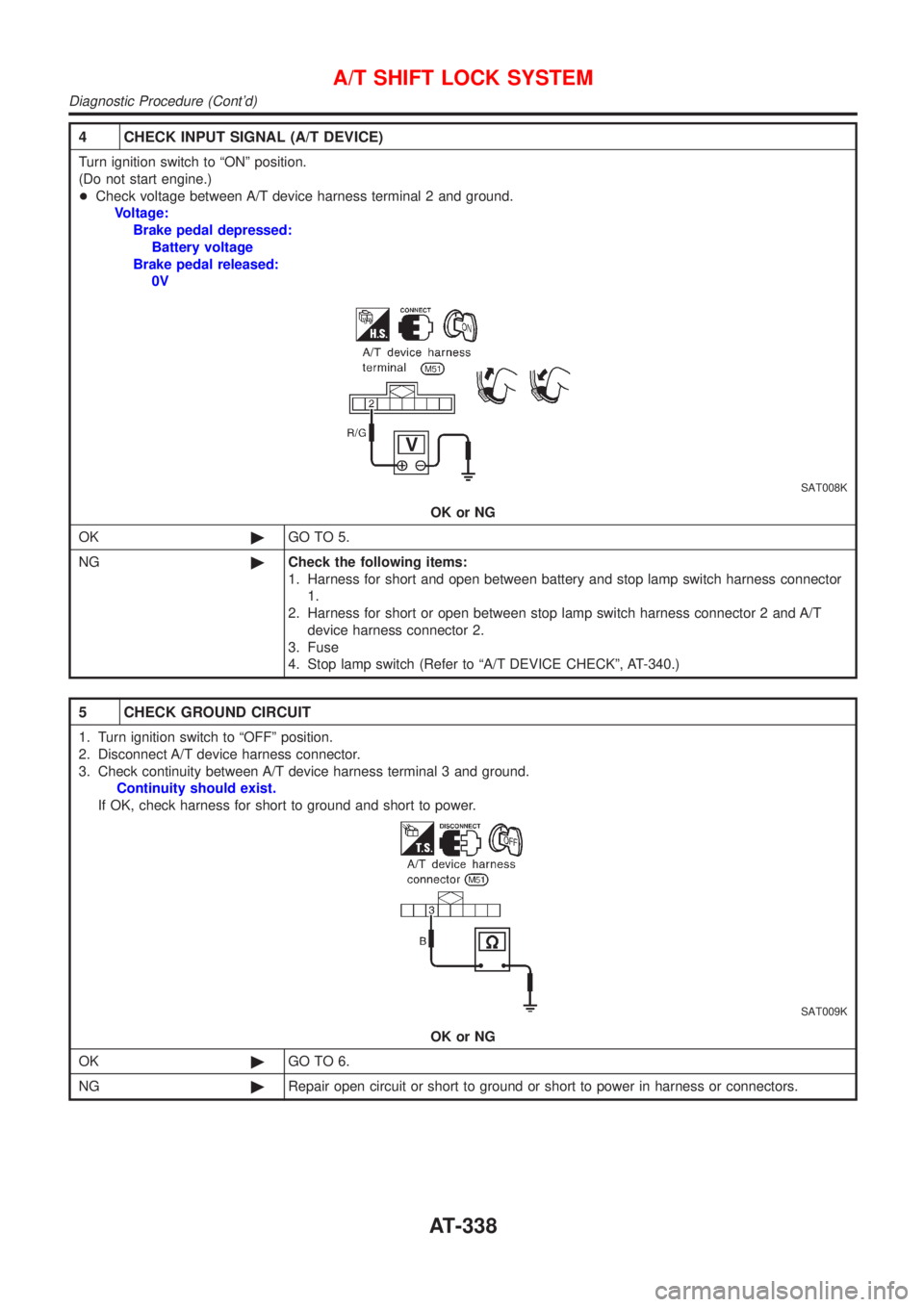
+Check voltage between A/T device harness terminal 2 and ground.
Voltage:
Brake pedal depressed:
Battery voltage
Brake pedal released:
0V
SAT008K
OK or NG
OK©GO TO 5.
NG©Check the following items:
1. Harness for short and open between battery and stop lamp switch harness connector
1.
2. Harness for short or open between stop lamp switch harness connector 2 and A/T
device harness connector 2.
3. Fuse
4. Stop lamp switch (Refer to ªA/T DEVICE CHECKº, AT-340.)
5 CHECK GROUND CIRCUIT
1. Turn ignition switch to ªOFFº position.
2. Disconnect A/T device harness connector.
3. Check continuity between A/T device harness terminal 3 and ground.
Continuity should exist.
If OK, check harness for short to ground and short to power.
SAT009K
OK or NG
OK©GO TO 6.
NG©Repair open circuit or short to ground or short to power in harness or connectors.
A/T SHIFT LOCK SYSTEM
Diagnostic Procedure (Cont'd)
AT-338
Page 1525 of 2493
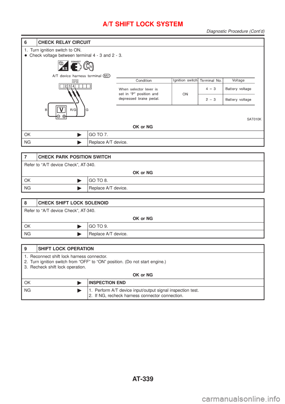
6 CHECK RELAY CIRCUIT
1. Turn ignition switch to ON.
+Check voltage between terminal4-3and2-3.
SAT010K
OK or NG
OK©GO TO 7.
NG©Replace A/T device.
7 CHECK PARK POSITION SWITCH
Refer to ªA/T device Checkº, AT-340.
OK or NG
OK©GO TO 8.
NG©Replace A/T device.
8 CHECK SHIFT LOCK SOLENOID
Refer to ªA/T device Checkº, AT-340.
OK or NG
OK©GO TO 9.
NG©Replace A/T device.
9 SHIFT LOCK OPERATION
1. Reconnect shift lock harness connector.
2. Turn ignition switch from ªOFFº to ªONº position. (Do not start engine.)
3. Recheck shift lock operation.
OK or NG
OK©INSPECTION END
NG©1. Perform A/T device input/output signal inspection test.
2. If NG, recheck harness connector connection.
A/T SHIFT LOCK SYSTEM
Diagnostic Procedure (Cont'd)
AT-339
Page 1526 of 2493
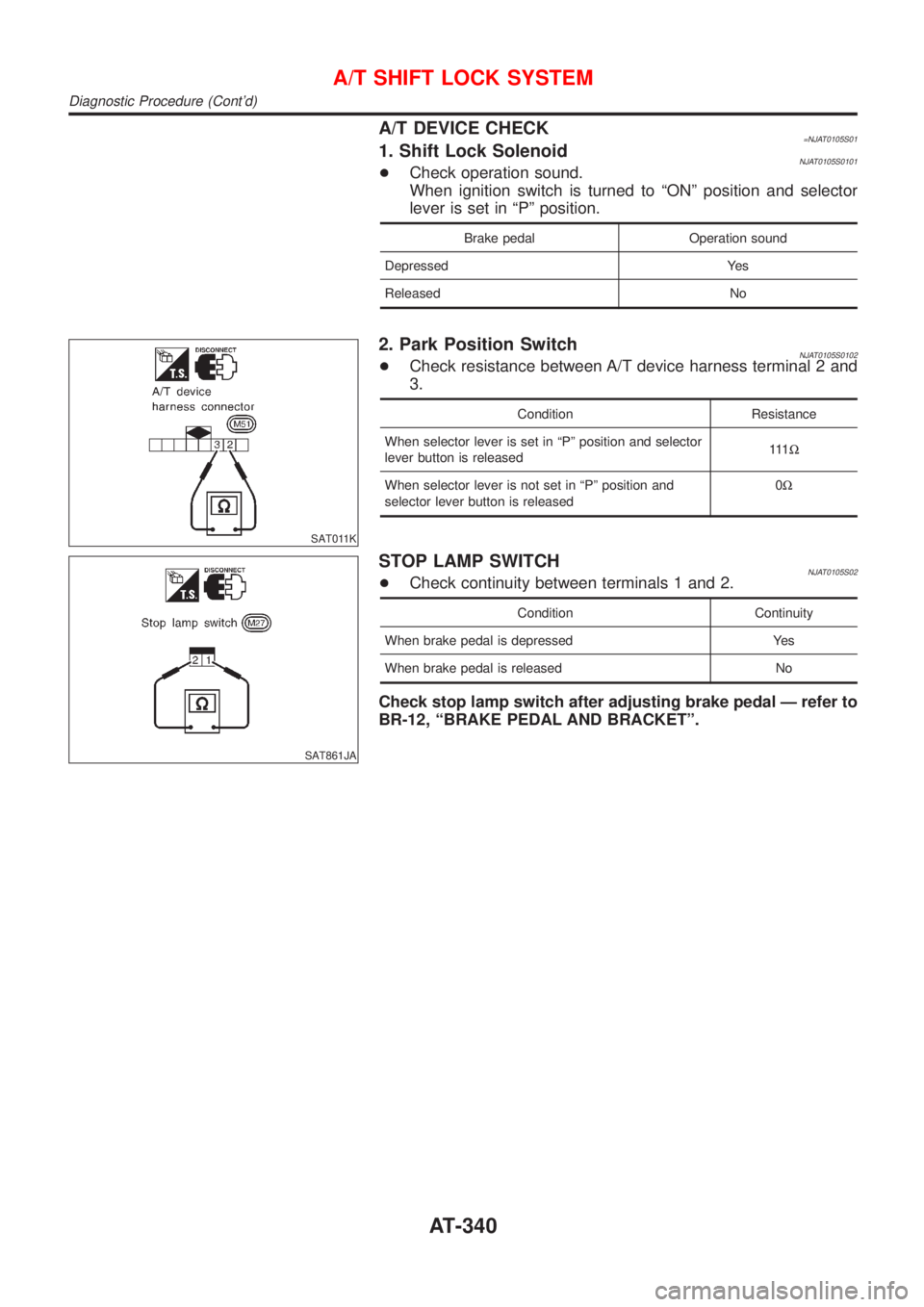
A/T DEVICE CHECK=NJAT0105S011. Shift Lock SolenoidNJAT0105S0101+Check operation sound.
When ignition switch is turned to ªONº position and selector
lever is set in ªPº position.
Brake pedal Operation sound
Depressed Yes
Released No
SAT011K
2. Park Position SwitchNJAT0105S0102+Check resistance between A/T device harness terminal 2 and
3.
Condition Resistance
When selector lever is set in ªPº position and selector
lever button is released111W
When selector lever is not set in ªPº position and
selector lever button is released0W
SAT861JA
STOP LAMP SWITCHNJAT0105S02+Check continuity between terminals 1 and 2.
Condition Continuity
When brake pedal is depressed Yes
When brake pedal is released No
Check stop lamp switch after adjusting brake pedal Ð refer to
BR-12, ªBRAKE PEDAL AND BRACKETº.
A/T SHIFT LOCK SYSTEM
Diagnostic Procedure (Cont'd)
AT-340
Page 1528 of 2493
SAT854J
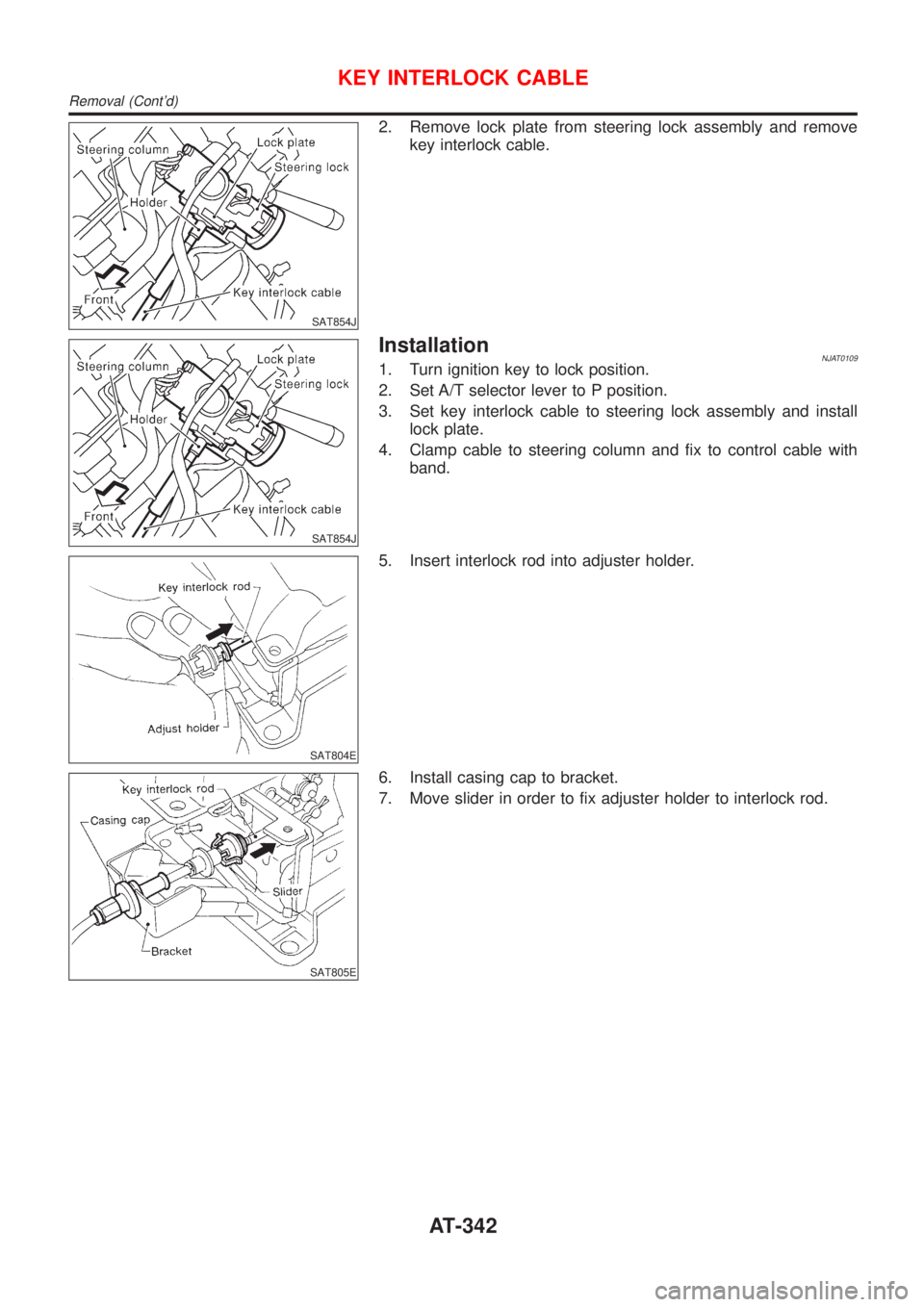
2. Remove lock plate from steering lock assembly and remove
key interlock cable.
SAT854J
InstallationNJAT01091. Turn ignition key to lock position.
2. Set A/T selector lever to P position.
3. Set key interlock cable to steering lock assembly and install
lock plate.
4. Clamp cable to steering column and fix to control cable with
band.
SAT804E
5. Insert interlock rod into adjuster holder.
SAT805E
6. Install casing cap to bracket.
7. Move slider in order to fix adjuster holder to interlock rod.
KEY INTERLOCK CABLE
Removal (Cont'd)
AT-342
Page 1700 of 2493

Inspection - Lining .....................................................33
Installation ..................................................................33
REAR DISC BRAKE (CAM & STRUT TYPE)..............35
Component ................................................................35
Pad Replacement ......................................................35
Removal .....................................................................37
Disassembly...............................................................37
Inspection...................................................................38
CALIPER.................................................................38
ROTOR...................................................................39
Assembly ...................................................................39
Installation ..................................................................42
REAR DISC BRAKE (BALL & RAMP TYPE)..............43
Component ................................................................43
Pad Replacement ......................................................43
Removal .....................................................................45
Disassembly...............................................................45
Inspection...................................................................45
CALIPER.................................................................45
ROTOR...................................................................46
Installation ..................................................................46
PARKING BRAKE CONTROL......................................47
Components...............................................................47
Removal and Installation ...........................................47
Inspection...................................................................47
Adjustment .................................................................48
ABS
DESCRIPTION...............................................................49
Purpose......................................................................49
ABS (Anti-Lock Brake System) Operation ................49
ABS Hydraulic Circuit ................................................49
System Components .................................................50
System Description ....................................................50
SENSOR.................................................................50
CONTROL UNIT......................................................50
ABS ACTUATOR AND ELECTRIC UNIT....................50
Component Parts and Harness Connector
Location .....................................................................52
Schematic ..................................................................53
Wiring Diagram - ABS - .............................................54
ON BOARD DIAGNOSTIC SYSTEM
DESCRIPTION...............................................................58
CONSULT-II ...............................................................58
CONSULT-II APPLICATION TO ABS..........................58
ECU (ABS CONTROL UNIT) PART NUMBER
MODE
.....................................................................58
CONSULT-II Inspection Procedure............................58
SELF-DIAGNOSIS PROCEDURE..............................58
SELF-DIAGNOSTIC RESULTS MODE.......................60
DATA MONITOR PROCEDURE................................61
ACTIVE TEST PROCEDURE....................................62
DATA MONITOR MODE...........................................63
ACTIVE TEST MODE...............................................63
TROUBLE DIAGNOSIS - INTRODUCTION..................64
How to Perform Trouble Diagnoses for Quick
and Accurate Repair ..................................................64
INTRODUCTION......................................................64
TROUBLE DIAGNOSIS - BASIC INSPECTION...........65
Preliminary Check......................................................65
Ground Circuit Check ................................................68
ABS ACTUATOR AND ELECTRIC UNIT GROUND.....68
TROUBLE DIAGNOSES FOR SELF-DIAGNOSTIC
ITEMS.............................................................................69
Wheel Sensor or Rotor ..............................................69
DIAGNOSTIC PROCEDURE.....................................69
ABS Actuator Solenoid Valve or Solenoid Valve
Relay ..........................................................................72
DIAGNOSTIC PROCEDURE.....................................72
Motor Relay or Motor.................................................75
DIAGNOSTIC PROCEDURE.....................................75
Low Voltage ...............................................................77
DIAGNOSTIC PROCEDURE.....................................77
Control Unit ................................................................79
DIAGNOSTIC PROCEDURE.....................................79
TROUBLE DIAGNOSES FOR SYMPTOMS.................80
1. ABS Works Frequently ..........................................80
2. Unexpected Pedal Action ......................................80
3. Long Stopping Distance ........................................81
4. ABS Does Not Work ..............................................82
5. Pedal Vibration and Noise.....................................83
6. ABS Warning Lamp Does Not Come On
When Ignition Switch Is Turned On...........................84
7. ABS Warning Lamp Stays On When Ignition
Switch Is Turned On ..................................................86
REMOVAL AND INSTALLATION.................................88
Wheel Sensors ..........................................................88
ABS Actuator and Electric Unit..................................89
REMOVAL...............................................................89
INSTALLATION........................................................89
Sensor Rotor..............................................................90
REMOVAL...............................................................90
INSTALLATION........................................................90
SERVICE DATA AND SPECIFICATIONS (SDS).........91
General Specifications ...............................................91
Disc Brake .................................................................91
Drum Brake................................................................91
Brake Pedal ...............................................................92
Parking Brake ............................................................92
CONTENTS(Cont'd)
BR-2