Page 106 of 2493
SEM519G
6. Install camshaft sprocket bolts and tighten them to correct
torque.
+Apply new engine oil to bolt threads and seat surface.
SEM520G
7. Install chain tensioner.
+Before installing chain tensioner, insert a suitable pin into
pin hole of chain tensioner.
+After installing chain tensioner, remove the pin.
8. Install timing chain guide.
SEM893F
9. Install O-rings to cylinder block.
SEM894F
10. Before installing front cover, remove all traces of liquid gasket
from mating surface using a scraper.
+Also remove traces of liquid gasket from mating surface of
cylinder block.
SEM677G
11. Apply a continuous bead of liquid gasket to mating surface of
front cover.
+Check alignment of mating marks on chain and crankshaft
sprocket.
+Align oil drive spacer with oil pump.
+Place timing chain to the side of chain guide. This pre-
vents the chain from making contact with water seal area
of front cover.
TIMING CHAINQG
Installation (Cont'd)
EM-28
Page 107 of 2493

SEM896F
12. Install front cover.
Bolt No. Tightening torque N´m (kg-m, in-lb) ª!º mm (in)
a. 6.9 - 9.5 (0.70 - 0.97, 61 - 84) 20 (0.79)
b. 6.9 - 9.5 (0.70 - 0.97, 61 - 84) 40 (1.57)
c. 17 - 24 (1.7 - 2.4, 148 - 208*) 70 (2.76)
d. 6.9 - 9.5 (0.70 - 0.97, 61 - 84) 72.8 (2.866)
e. 6.9 - 9.5 (0.70 - 0.97, 61 - 84) 12 (0.47)
*: 12 - 17 ft-lb
SEM897F
+Make sure two O-rings are present.
+Be careful not to damage oil seal when installing front
cover.
SEM009G
13. Install cylinder head bolts at engine front side.
+Tightening procedure
Tightening bolts (1 - 4) to 6.3 to 8.3 N´m (0.64 to 0.85 kg-m,
55.8 to 73.5 in-lb).
SEM945F
14. Install oil pump drive spacer.
SEM104G
15. Install water pump and water pump pulley.
Refer to LC-14, ªWater Pumpº.
16. Install idler pulley and bracket.
17. Install RH engine mounting bracket.
18. Install RH engine mounting.
19. Install oil strainer.
20. Install oil pan. Refer to EM-20, ªInstallationº.
21. Install crankshaft pulley.
22. Remove ring gear stopper.
23. Install starter motor.
TIMING CHAINQG
Installation (Cont'd)
EM-29
Page 109 of 2493
SEM909F
ReplacementNJEM0015VALVE OIL SEALNJEM0015S011. Remove rocker cover.
2. Remove camshaft.
3. Remove valve spring. Refer to EM-36.
4. Remove valve oil seal with Tool.
Piston concerned should be set at TDC to prevent valve from
falling.
SEM910F
5. Apply new engine oil to new valve oil seal and install it with
Tool.
SEM911F
FRONT OIL SEALNJEM0015S021. Remove the following parts:
+Engine under cover
+RH engine side cover
+Alternator and power steering drive belts
+Crankshaft pulley
2. Remove front oil seal from front cover.
+Be careful not to scratch front cover.
SEM715A
SEM912F
3. Apply new engine oil to new oil seal and install it using a suit-
able tool.
+Install new oil seal in the direction shown.
OIL SEALQG
Replacement
EM-31
Page 110 of 2493
SEM096F
REAR OIL SEAL=NJEM0015S031. Remove transaxle. Refer to MT-23 or AT-346, ªREMOVAL AND
INSTALLATIONº.
2. Remove flywheel or drive plate.
3. Remove rear oil seal.
+Be careful not to scratch rear oil seal retainer.
SEM715A
4. Apply new engine oil to new oil seal and install it using a suit-
able tool.
+Install new oil seal in the direction shown.
SEM097F
OIL SEALQG
Replacement (Cont'd)
EM-32
Page 112 of 2493

CAUTION:
+When installing camshaft and oil seal, lubricate contacting
surfaces with new engine oil.
+When tightening cylinder head bolts, camshaft sprocket
bolts and camshaft bracket bolts, lubricate bolt threads
and seat surfaces with new engine oil.
+Attach tags to valve lifters so as not to mix them up.
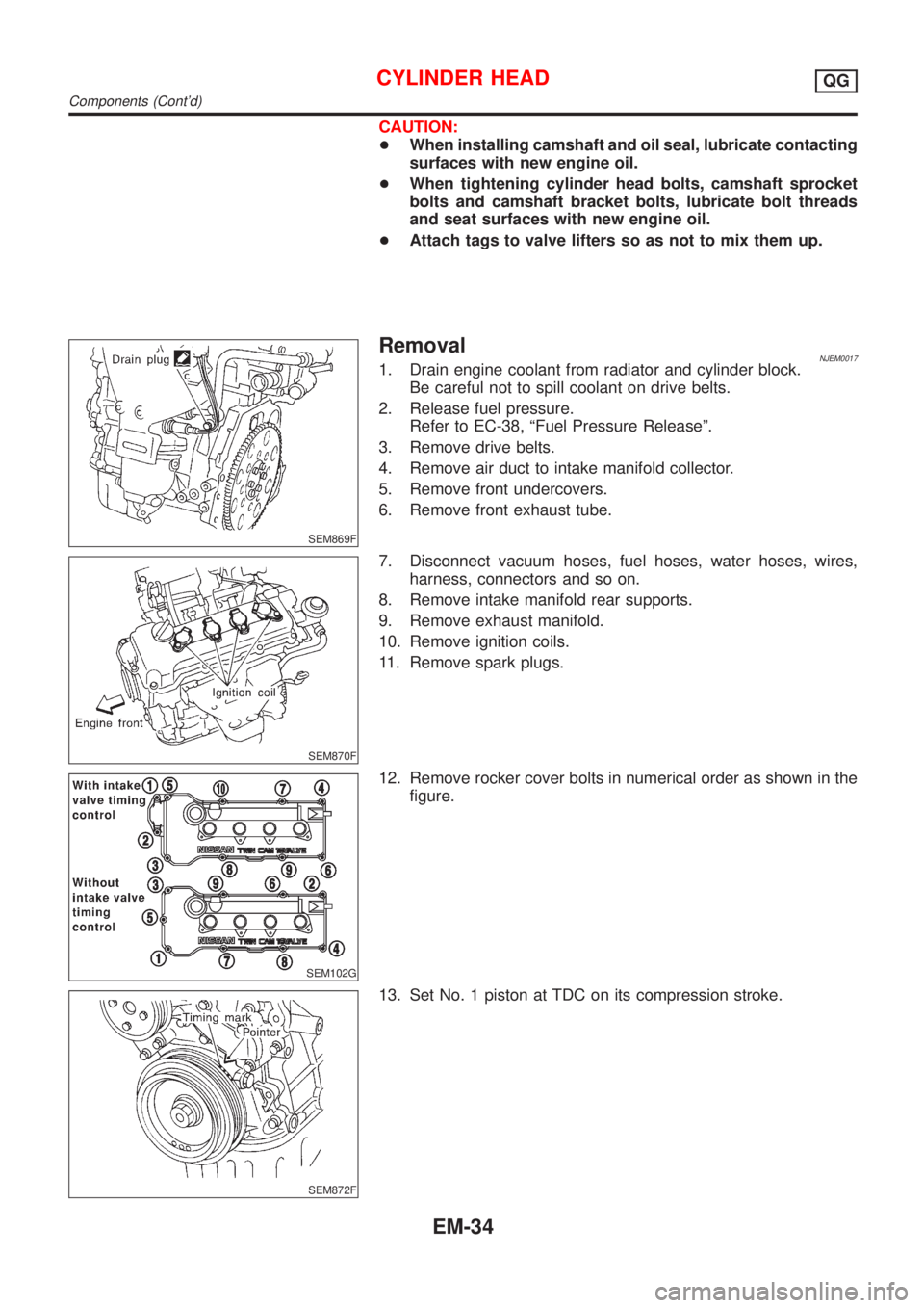
SEM869F
RemovalNJEM00171. Drain engine coolant from radiator and cylinder block.
Be careful not to spill coolant on drive belts.
2. Release fuel pressure.
Refer to EC-38, ªFuel Pressure Releaseº.
3. Remove drive belts.
4. Remove air duct to intake manifold collector.
5. Remove front undercovers.
6. Remove front exhaust tube.
SEM870F
7. Disconnect vacuum hoses, fuel hoses, water hoses, wires,
harness, connectors and so on.
8. Remove intake manifold rear supports.
9. Remove exhaust manifold.
10. Remove ignition coils.
11. Remove spark plugs.
SEM102G
12. Remove rocker cover bolts in numerical order as shown in the
figure.
SEM872F
13. Set No. 1 piston at TDC on its compression stroke.
CYLINDER HEADQG
Components (Cont'd)
EM-34
Page 123 of 2493

Unit: mm (in)
For adjusting For checking
HotCold* (reference
data)Hot
Intake0.32 - 0.40
(0.013 - 0.016)0.25 - 0.33
(0.010 - 0.013)0.21 - 0.49
(0.008 - 0.019)
Exhaust0.37 - 0.45
(0.015 - 0.018)0.32 - 0.40
(0.013 - 0.016)0.30 - 0.58
(0.012 - 0.023)
*: At a temperature of approximately 20ÉC (68ÉF)
Whenever valve clearances are adjusted to cold specifications, check that
the clearances satisfy hot specifications and adjust again if necessary.
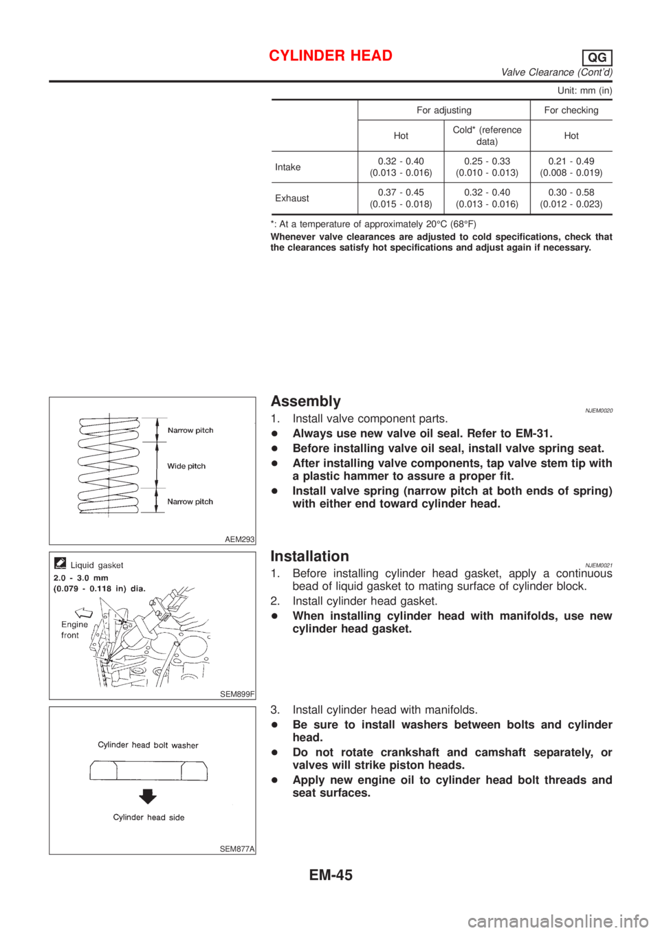
AEM293
AssemblyNJEM00201. Install valve component parts.
+Always use new valve oil seal. Refer to EM-31.
+Before installing valve oil seal, install valve spring seat.
+After installing valve components, tap valve stem tip with
a plastic hammer to assure a proper fit.
+Install valve spring (narrow pitch at both ends of spring)
with either end toward cylinder head.
SEM899F
InstallationNJEM00211. Before installing cylinder head gasket, apply a continuous
bead of liquid gasket to mating surface of cylinder block.
2. Install cylinder head gasket.
+When installing cylinder head with manifolds, use new
cylinder head gasket.
SEM877A
3. Install cylinder head with manifolds.
+Be sure to install washers between bolts and cylinder
head.
+Do not rotate crankshaft and camshaft separately, or
valves will strike piston heads.
+Apply new engine oil to cylinder head bolt threads and
seat surfaces.
CYLINDER HEADQG
Valve Clearance (Cont'd)
EM-45
Page 125 of 2493

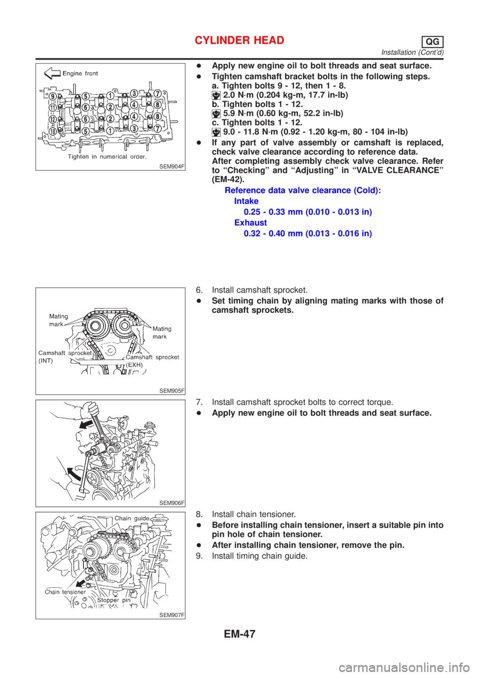
SEM904F
+Apply new engine oil to bolt threads and seat surface.
+Tighten camshaft bracket bolts in the following steps.
a. Tighten bolts9-12,then1-8.
2.0 N´m (0.204 kg-m, 17.7 in-lb)
b. Tighten bolts1-12.
5.9 N´m (0.60 kg-m, 52.2 in-lb)
c. Tighten bolts1-12.
9.0 - 11.8 N´m (0.92 - 1.20 kg-m, 80 - 104 in-lb)
+If any part of valve assembly or camshaft is replaced,
check valve clearance according to reference data.
After completing assembly check valve clearance. Refer
to ªCheckingº and ªAdjustingº in ªVALVE CLEARANCEº
(EM-42).
Reference data valve clearance (Cold):
Intake
0.25 - 0.33 mm (0.010 - 0.013 in)
Exhaust
0.32 - 0.40 mm (0.013 - 0.016 in)
SEM905F
6. Install camshaft sprocket.
+Set timing chain by aligning mating marks with those of
camshaft sprockets.
SEM906F
7. Install camshaft sprocket bolts to correct torque.
+Apply new engine oil to bolt threads and seat surface.
SEM907F
8. Install chain tensioner.
+Before installing chain tensioner, insert a suitable pin into
pin hole of chain tensioner.
+After installing chain tensioner, remove the pin.
9. Install timing chain guide.
CYLINDER HEADQG
Installation (Cont'd)
EM-47
Page 128 of 2493

WARNING:
+Position vehicle on a flat and solid surface.
+Place chocks at front and back of rear wheels.
+Do not remove engine until exhaust system has com-
pletely cooled off, otherwise, you may burn yourself
and/or fire may break out in fuel line.
+Before disconnecting fuel hose, release pressure.
Refer to EC-38, ªFuel Pressure Releaseº.
+Be sure to lift engine and transaxle in a safe manner.
+For engines not equipped with engine slingers, attach
proper slingers and bolts described in PARTS CATALOG.
CAUTION:
+When lifting engine, be sure to clear surrounding parts.
Use special care near accelerator wire casing, brake lines
and brake master cylinder.
+When lifting the engine, always use engine slingers in a
safe manner.
+When removing drive shaft, be careful not to damage
grease seal of transaxle.
+Before separating engine and transaxle, remove crank-
shaft position sensor (POS) from the cylinder block
assembly.
+Always be extra careful not to damage edge of crankshaft
position sensor (POS), or signal plate teeth.
Engine cannot be removed separately from transaxle. Remove
engine with transaxle as an assembly.
REMOVALNJEM0022S011. Drain coolant from radiator and cylinder block. Refer to LC-17,
ªChanging Engine Coolantº.
2. Remove coolant reservoir tank and bracket.
3. Drain engine oil.
4. Remove battery and battery tray.
5. Remove air cleaner and air duct.
6. Remove drive belts.
7. Remove alternator and air conditioner compressor from
engine.
8. Remove power steering oil pump from engine and position
aside.
Power steering oil pump does not need to be disconnected
from power steering tubes.
ENGINE ASSEMBLYQG
Removal and Installation (Cont'd)
EM-50